01
Installation Process
Product Front View
(Front View)
1. Programmable AC Power Outlets
Product Rear View
1. AC Power Source Inlet
2. Power Switch
3. Circuit Breaker Switches
4. 485 Output: In a daisy chained installation this is
the chain out port of the parent station.
5. 485 Input: In a daisy chained installation this is
the chain in port of the child station.
6. 232C: Used for a serial connection (either from a
modem or a direct terminal connection from a
local console) for monitoring, software updating,
etc.
Ì7. Ethernet: Used for browser connections to the
GN0116 from remote systems.
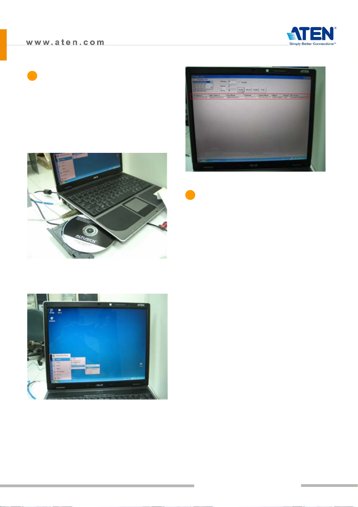
Hardware Installation
IP Setting
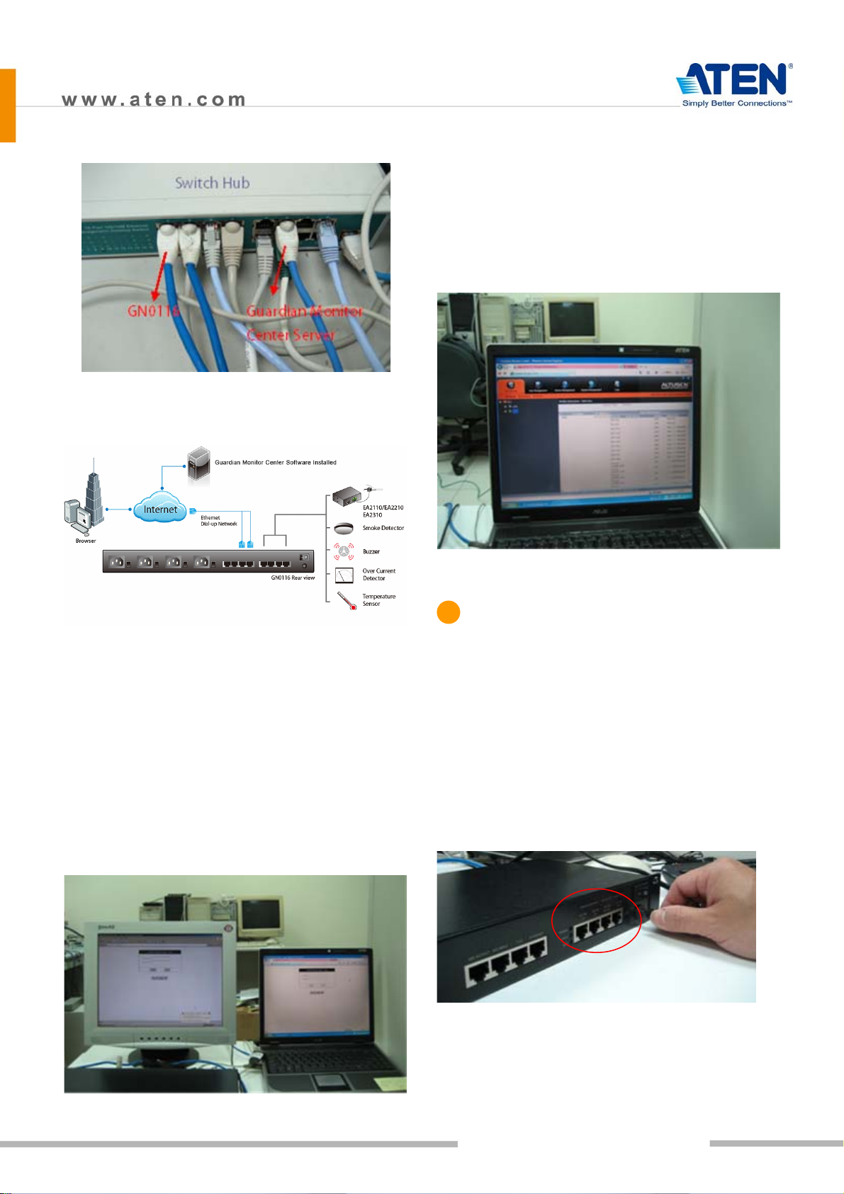
Guardian Monitor Center Server
Installation
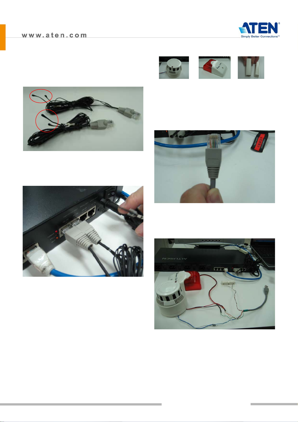
Sensor Installation
Configuration/Operation
8. Ports101, 102; 103,104; 105,106; and 107,108 are
digital output ports. The output voltage is 12VDC;
50mA. They can operate buzzers, warning lights
and other similar devices. They can also be
connected to an extension unit and used as
programmable power outlets.
9. Ports 1, 2 and 3, 4 are resistance type analog
input ports. The input resistance ranges from
2~205KΩ. The ports have 1024 levels of
resolution. With appropriate drivers, they can be
connected to thermistor or other
resistance-output sensors (such as CDS sensors).
10. Ports 201,202 are digital input ports (dry contact).
They can be connected to On/Off-type output
sensors (such as intrusion, access control, smoke,
and leakage sensors).
Ì
11. Ports 31, 32 are voltage-type analog input ports.
The input voltage ranges from 0~5VDC. The ports
have 1024 levels of resolution. With appropriate
drivers, they can be connected to sensors with
0~5 VDC output voltage, such as AC/DC voltage
sensors, current sensors and humidity sensors.
12. Reset Switch
Ì
13. Power Input
GN0116 Guardian Over the NET™
Installation Guide