FEAS LDR50 User manual

3. Montage
Das LDR kann direkt an DIN-Hutschiene montiert werden, oder an
die Wand geschraubt werden. Beachten Sie dazu die Hinweise.
ACHTUNG! Zur besseren Wärmeabfuhr sollte das Gerät einen
Freiraum von 15mm haben.
3. Installation
The LDR can be mounted on rail, or at the wall. Take notice of the
mounting alternatives attached.
CAUTION! For improved heat dissipation, the device
should have a minimum free space of 15 mm.
4. Elektrischer Anschluss
Das Gerät laut Anschluss-Schema unten anschließen. Hierbei un-
bedingt die allgemeinen Sicherheitsvorschriften beachten. Unsach-
gemäßer Anschluss kann zu einem Defekt des Gerätes führen.
4. Electrical connection
Take care of a correct electrical connection. Take the wiring diagram
at the bottom of this side as help. Inappropriate connection can
cause a defect of the device.
Verbraucher (z.B. Schütze, Motoren, Magnetventile, etc.) die
nicht ordnungsgemäß nach den relevanten Richtlinien entstört
sind (z.B. Varistoren, RC-Glieder, etc), können zur Störung
bzw. Zerstörung des Netzgerätes führen.
Consumers (e.g. contactors, motors, solenoid valves etc.)
which have not been correctly interference-suppressed in
accordance to the relevant guidelines (e.g. varistors, RC
elements, etc.) may cause power supply regulation to
malfunction.
- konform
LDR5012-W/H, LDR5024-W/H
Für die Modelle: Complementing the:
2. Funktionsweise
Das LDR ist ein Akku-Modul zur Überbrückung von Netzausfällen im
DC-Versorgungsnetz. Die Versorgungsdauer hängt von der Größe
des Belastungsstrom der Verbraucher ab. Die Kühlung erfolgt über
Luftkonvektion.
2. Mode of operation
The LDR is a accu-modul to buffer the DC-circuit in case of power
blackouts. The supply duration depends on the magnitude of the
load-current of the consumers. The cooling of the device takes place
via air convection.
1. Allgemeine Sicherheitsvorschriften
Beim Umgang mit Produkten, die mit elektrischen Spannungen in Berührung kommen,
müssen die gültigen VDE / IEC / EN Vorschriften beachtet werden. Besonders sei auf
folgende Vorschriften hingewiesen: VDE 0100, VDE 0550 / 0551, VDE 0711, VDE 0860,
IEC 664, IEC 742, IEC 570, IEC 65
Bei Nichtbeachtung der Bedienungsanleitung oder der Anschlußvorschrift, z.B. bei
Vertauschen der Anschlußklemmen, kann das Gerät oder die Anlage beschädigt werden
und der Betreiber verliert seinen möglichen Haftungsanspruch.
Werkzeuge dürfen an Geräten, Bauteilen oder Baugruppen nur benutzt werden, wenn
sichergestellt ist, dass die Geräte von der Versorgungs-spannung getrennt sind und
interne elektrische Bauteile entladen sind.
Vor dem Öffnen des Gerätes den Netzstecker ziehen und sicherstellen, dass das Gerät
spannungslos ist und bleibt. Bauteile, Baugruppen oder Geräte dürfen nur in Betrieb
genommen werden, wenn sie vorher in ein berührungssicheres Gehäuse eingebaut
wurden. Während des Einbaus müssen sie stromlos sein.
Spannungsführende Kabel oder Leitungen mit denen das Gerät, das Bauteil oder die
Baugruppe verbunden sind müssen stets auf Isolationsfehler oder Bruchstellen
untersucht werden. Bei Feststellen eines Fehlers in der Zuleitung muß das Gerät
unverzüglich aus dem Verkehr genommen werden, bis die defekte Leitungen
ausgewechselt worden sind.
Der Anwender hat dafür Sorge zu tragen, dass die angegebenen Gerätedaten nicht
überschritten werden.
Wenn aus den vorgelegten Beschreibungen für den Anwender oder Erwerber nicht
eindeutig hervorgeht, welche Kennwerte für ein Gerät oder Bauteil gelten, so muss stets
ein Fachmann um Auskunft ersucht werden.
Im übrigen unterliegt die Einhaltung von Bau- und Sicherheitsvorschriften aller Art (VDE,
TÜV, Berufsgenossenschaften ) dem Anwender / Käufer.
1.General safety rules
When working with products which are in contact to dangerous electrical voltages,
attention must be payed to the relevant valid VDE / IEC / EN regulations. Especialy
with refrence to the following rules:
VDE 0100, VDE 0550 / 0551, VDE 0711, VDE 0860, IEC 664, IEC 742, IEC 570,
IEC 65
In case of non-observance of this instructions the unit or other equipment might be
damaged and no warranty or liability could be accepted.
When it is necessary to use tools on the device components parts or subassemblies
make sure that the power is disconnected from the device and all capacities are
discharged.
Before opening the equipment disconnect the power cord and make sure that the
contacts are not energized. It is only allowed to take components parts,
subassemblies or device into operation if they are mounted in an insulated housing.
During the installation all devices have to be disconnected from power sources.
Power cords and leads which are connected to the device, components or
subassemblies have to be inspected for damaged insulation. If a failure is detected
the device or the subassembly has to be put out of service at once. It is not allowed
to take the device or the subassembly into operation before replacing the damaged
power cord.
It is up to the user’s responsibility that the specification limits of the device are not
exceeded.
If the user is not fully able to relate the technical guidelines, a technical adviser has
to be asked for information.
The observance of construction requirements and safety rules (VDE, IEC,
employers liability insurenance i.e.) is subject to the user/customer.
Für den ordnungsgemäßen Betrieb des Gerätes ist ein
Überspannungsschutz nach VDE0185-4 / EN62305-4,
eine Vorsicherung, gemäß Tabelle, und optional ein
Netzfilter vorzusehen.
For proper operation of the device provide an
overvoltage protection, according VDE0185-4 /
EN62305-4, an input fuse as shown in table and
optionally a line filter.
= LED an / on = LED aus / off
Eingang
Input Temperatur
Inhibit Akku voll
Accu full
Laden
Charge Abschaltwarnung
Cut-off warning Status
LED
Der Akku ist geladen, normaler Betrieb.
Accu is charged, normal operation.
Der Akku wird geladen, normaler Betrieb.
Accu is charging, normal operation.
Der LDR ist zu warm, der Akku ist voll, wird aber im Bedarfsfall nicht nachgeladen.
The temperature of the LDR is to high, the accu is full, but will not be recharged
if it’s necessary.
Der LDR ist im Pufferbetrieb, die Akku-Kapazität ist größer 80% .
The LDR runs in buffering mode, accu capacity is more than 80%
Abschaltwarnung, siehe auch Fernüberwachung 7.2.
Cut-off warning, see also remote monitoring 7.2.
Der LDR ist im Pufferbetrieb, die Akku-Kapazität ist kleiner 80% .
The LDR runs in buffering mode, accu capacity is less than 80%
Der LDR wird außerhalb des Arbeitstemperaturbereich betrieben. Der Akku wird
zum Selbstschutz nicht geladen.
The LDR is used outside operating temperature range. The accupack will not be
charged anymore to protect the accupack.
5. LED Anzeigen 5. LED Display
Kontaktbelastung der Relais:
- max. Schaltstrom 0,5Amp.
- max. Schaltspannung 30VDC oder 250VAC
Contact-load of the relays:
- max. switched current 0.5Amp.
- max. switched voltage 30VDC or 250VAC
Anschlußbeispiel/ Wiring Example
141
(+20)
160,5
83
49 35 57
Uout
DC-Ausgang
DC-output
+
-
Relais 1 - Schließer
(siehe Punkt 7.1 - Fernüberwachung)
Relay 1 - normally open contact
(see point 7.1 - Remote monitoring)
Relais 2 - Wechsler
(siehe Punkt 7.2 - Fernüberwachung)
Relay 2 - change-over contact
(See point 7.2 - Remote monitoring)
12
57
6
Der Ausgang kann in Abhängigkeit von der Akkuspannung auch bei fehlender
Eingangsspannung Spannungsführend sein.
There is a voltage available on the output depending on the accu-voltage
even if DC-Input is disconnected.
!
Eingang
Input
Uin L1
N
115 / 230 VAC
Netzteil PSU18032
!
Zum erreichen der maximalen Ladekapazität ist zwingend
erforderlich:
1)Bei der ersten Inbetriebnahme des Ladereglers die Akkus
mindestens 24 Stunden zu laden.
2)Die Akkus durch mindestens 3 volle Lade- und Entladezyklen
bei gleichzeitiger Stromentnahme (ca 50%) zu konditionieren.
Wenn die oben beschriebene Prozedur nicht durchgeführt wird,
kann es vorkommen, dass schon nach wenigen Minuten die
LED “Akku voll” leuchtet, obwohl der Akku noch nicht
vollständig geladen ist.
For reaching the optimal capacity it is strongly essential:
1)With the first beginning of operation to charge the accus for
min. 24 hours.
2)To charge and discharge the accus minimum three times, in
order to condition the accus. This procedure should be made
with ca. 50% output load.
If the procedure mentioned above are not enforced, it is
possible that the LED “Akku voll” is switching on even if the
accu is not fully charged.
Betriebsanleitung
Bitte sorgfältig beachten!
Operating instructions
Please observe carefully!
LDR50
8. Betriebshinweise
Um die eingebauten Akkus vor unzulässiger Erwärmung zu
schützen, ist das LDR mit einem thermischen Ladeschutz
ausgerüstet.
Dieser Ladeschutz bewirkt, das für den oben genannten Fall, die
Akkus nicht mehr geladen bzw. nachgeladen werden und so kein
voller Pufferbetrieb gewährleistet ist.
Aus diesem Grunde bitte für ausreichende Kühlung sorgen!
8. Tips for operation
In order to protect the built-in storage batteries against
inadmissible heating, the LDR is equipped with a thermal
charge protection.
This charge protection has the effect that, for the above-
mentioned case, the accus won’t be charged or recharged
anymore. Full buffering mode is not possible.
For this reason please provide for sufficient cooling!
Eingangsspannung
Input voltage
Kapazität
Capacity
Typ
Ausgangsspannung
folgt der Akkuspannung (U )
Puffer
Outputvoltage
follows the accu voltage (U )
buffer
18 ... 68 VDC 18 ... 68 VDC 28 ... 68 VDC
LDR5024-5
LDR5012-6 LDR5012-9
ca. 2A ca. 2A ca. 1A
10,0V ....14,0V
DC DC 10,0V ....14,0V
DC DC 20,0V ....26,0V
DC DC
siehe Gehäuse siehe Gehäuse
5A 5A 5A
Ladestrom
Charging current
Ausgangsstrom
Output current
Maße
dimensions
Gewicht
weight
Pufferzeit
Hold-up-time
Wirkungsgrad
Efficiency
Arbeitstemperatur
Operating temperature
BxHxT
WxHxD
ca. 3,5kg ca. 3,5kg
83mm x 161mm x 160,5mm 83mm x 161mm x 160,5mm
typ. 2A 2h typ. 2A 4,5h
5 Ah 10 Ah
typ. 2A 2,0h
5,2 Ah
88 % 88 % 88 %
28 ... 68 VDC
LDR5024-3
ca. 1A
20,0V ....26,0V
DC DC
5A
typ. 2A 0,6h
2,5 Ah
88 %
see face plate see face plate
7. Fernüberwachung
Um eine Fernüberwachung des Akkupacks zu ermöglichen, sind 2
Relais eingebaut. Die Relaiskontakte sind mit max. 0,5 Amp. bei
max. 250VAC oder 30VDC belastbar und auf Klemmen geführt.
.
7.1 Relais 1 (Klemmen 1/2) - Schließer
Bei vorhandener Eingangsspannung sind die Kontakte 1 und 2
geschlossen. Sobald die Eingangsspannung unterbricht, öffnet
das Relais und es kann die Statusmeldung “Netz fehlt”
entnommen werden.
7.2 Relais 2 (Klemmen 5 / 6 / 7) - Wechsler
A) 5 - 6 geschlossen
Ist der Akku defekt oder die Ausgangsspannung sinkt im
Pufferbetrieb unter eine bestimmte Grenze (21,0V bei der 24V-
Version / 11,1 V bei der 12V-Version), so schließt das Relais
und es kann die Statusmeldung “Akku-Ladung kritisch”
entnommen werden. Der Abschaltzeitpunkt des LDR, ist
abhängig von der Stromentnahme.
B)5 - 7 geschlossen
Sinkt die Ausgangsspannung unter einen Wert von 19,6V
(24V-Version) bzw. 9,8V (12V-Version) wird die Ausgangs-
spannung abgeschaltet, um die Akku’s vor “Tiefen-
entladung” zu schützen.
7. Remote monitoring
In order to enable a remote monitoring of the storage battery,
2 relays are built in. The relay-contacts can be loaded with a max.
0,5 Amp. by max. 250VAC or 30VDC and are routed to terminals.
7.1 Relay 1 (Terminal 1 / 2) - normally open contact
In the case of the presence of input voltage, Contacts 1 and 2
are closed. As soon as the input voltage is interrupted, the relay
opens and “Mains Network Failed” can be seen on the status
signal.
7.2 Relay 2 (Terminal 5 / 6 / 7) - change-over contact
A)5 - 6 closed
If the battery is damaged or the output voltage sinks below a
certain limit (21,0V with the 24V Version /11,1V with the 12V
Version), during the buffer mode. The relay contact closes and
the status signal “Battery-Charge critical” can be seen. The
switch-off point of the LDR is dependent on the current
consumption.
B)5 - 7 closed
If the output sinks below a value of 19,6V (24V Version) or
9,8V (12V Version) the output voltage is disconnected in
order to protect the storage battery against “Deep
Discharge”.
9. Batteriewechsel
1
Schritt 1: Eingangsspannung ausschalten.
Schritt 2: Gerät auf den Kopf stellen.
Schritt 3: Die 4 Inbusschrauben (M4) von der Bodenplatte lösen.
Schritt 4: Akkus herausnehmen und die Kabel von den
Kontakten abziehen.
Schritt 5: Neue Akkus an die Kabel anschließen (Auf korrekte
Polarität achten! Rote Kabel zum Plus-Pol, Blaue Kabel
zum Minus-Pol des Akkus)
Schritt 6: Akkus in den Batterieraum schieben.
Schritt 7: Bodenplatte wieder aufschrauben.
Schritt 8: Die alten Akkus ordnungsgemäß und umwelt-
gerecht entsorgen!
9.Battery replacment
1
Step 1: Switch off input voltage.
Step 2: Place device on its upper surface.
Step 3: Screw off the 4 Allen screws (M4) from the base plate.
Step 4: Remove storage batteries and pull the cables
from the contacts.
Step 5: Connect new storage batteries to the cables
(Note polarity! Red cable to the positive terminal
of the storage battery).
Step 6: Slide storage batteries into the battery compartment.
Step 7: Screw base plate back again.
Step 8: Dispose of the old storage batteries properly and
environmentally safely!
10. Technische Daten
18 - 68 VDC
28 - 68 VDC
-
ca. 120% I
< 200mV bei Laständerung 10...90%
< 25mV bei Netzspannungsänderung ±10%
< 10 mSek. bei Laständerung 10...90%
100%
siehe Gehäuseaufdruck
ab 40°C
siehe Arbeitstemperatur
natürliche Konvektion
empfohlener Freiraum je 15mm
bei 28VAC -10,0A träge
nicht erforderlich, da kurzschlussfest
im Gerät integriert
>380.000 h ohne Akku
-
Eingang / Ausgang 4,4 kVac
nach VDE 0806 / IEC 380
gemäß VDE 0871 B, EN 55022/B
Klasse 2
95% relative Feuchte im Jahresdurchschnitt
Betauung möglich - tropentauglich
IP 65
IP 20 (BGV A3)
>30g bei 33Hz in X,Y und Z,
nach IEC 60068-2-27 ohne Akku
DIN-Hutschiene oder Wandmontage aufschraubbar
siehe Gehäuseaufdruck des Gerätes
< 25mVss
bei 28VAC max. 5,1A
Transientenüberspannungsschutz Varistor
PELV (EN60204), SELV (EN 60950)
siehe Gehäuseaufdruck des Gerätes
Einschaltstromstoß
Ausgangsgrößen
Ausgangsspannung U
Strombegrenzung
Regelgrößen (Netzteil)
Regelabweichung Last
Regelabweichung Netz
Regelzeit
Betriebsdaten
Einschaltdauer (ED)
Arbeitstemperatur
Leistungsabweichung bei Temp.
Lagertemperaturbereich
Kühlung
Schutzeinrichtungen
Vorsicherung LDR5024
Ausgangssicherung
Überlastschutz
MTBF
Sicherheitsdaten
Prüfspannung Trafo
Hochspannungsfestigkeit
Funkenentstörgrad
Schutzklasse
Umgebungsfeuchte
Schutzart Gehäuse
Schutzart Klemmen
Rüttelfestigkeit
Angewandte Bauvorschriften
Nenn
Eingangsgleichspannung LDR5012
Eingangsgleichspannung LDR5024
Eingangsgrößen
Restwelligkeit (20MHz)
gemäß VDE
IEC
EN
CSA / UL
Befestigung
Mechanik
Stromaufnahme bei Nennlast LDR5024
Schutzbeschaltung
Schutzkleinspannung
Ausgangsstrom INenn
Nenn
bei 18VAC max. 4,5A / bei 24VAC max. 3,0A
Stromaufnahme bei Nennlast LDR5012
bei 28VAC -10,0A trägeVorsicherung LDR5012
83mm x 161mm x 160,5mm (BxHxT)Maße
ca. 3,5kgGewicht
CSA-C 22.2 / UL60950, UL508, UL1950, UL94
VDE 0100, 0110, 0113, 0551, 0806
IEC 60950-1,IEC61000-6-1-2-3-4,IEC60068-2-3
EN60950-1, EN61000-6-1-2-3-4,EN55022
EN55011,EN61000-3-3,EN50204,EN61558-2-17
EN60204,EN60529,EN61000-4-2-3-4-5-6-8-11
EN60068-1,EN60068-2-1-2-3-6-27-30
EN61010-1
IEC 60068-2-11-52,IEC 60529,
10. Technical Data
18 - 68 VDC
28 - 68 VDC
-
< 200mV with load variation 10...90%
< 25mV with supply variation ±10%
< 10 mSek. with load variation 10...90%
100%
see face plate
from 40°C
see operating temperature
selfcooling
recommended respective distance 15mm each
at 28VAC - 10.0A slow blow
not necessary, cont. short circuit proof
integrated into the device
>380,000 h without storage battery
-
Primary circuit - secondary circuit 4,4 kVac
acc. to VDE 0806 / IEC 380
in acc. to VDE 0871 B, EN 55022/B
Class 2
95% relative humidity, yearly average dewing
allowed for use in tropical ambient
IP 65
IP 20 (BGV A3)
>30g at 33Hz in X,Y and Z,
acc. to IEC 60068-2-27 without storage battery
DIN-Rail or wallmounting with screws
see face plate
< 25mVpp
at 28VAC max. 5.1A
Transient voltage suppressor Varistor
PELV (EN60204), SELV (EN 60950)
see face plate
Input current peak
Output data
Output voltage U
Current limiting
Control data (DC power supply)
Control deviation load
Control deviation supply
Control time
Operating data
Duty circle
Operating temperature range
Derating
Storage temperature range
Cooling
Safety devices
Fuse for input LDR5024
Fuse for output
Overload protection
MTBF
Safety data
Test voltage transformer
High voltage resistance
Degree of EMI suppresion
Protection class
Ambient humidity
Protective class enclosure
Protective class terminals
Vibration proof
Applied construction regulations
Nominal
Inputvoltage DC LDR5012
Inputvoltage DC LDR5024
Input data
Residual ripple (20MHz)
according to VDE
IEC
EN
CSA / UL
Mounting
Mechanics
Input current at nominal load LDR5024
Protective circuit
Extra low safety potential
Output current INominal
approx. 120% INominal
Input current at nominal load LDR5012 at 18VAC max. 4.5A / at 24VAC max. 3.0A
at 28VAC - 10.0A slow blow
Fuse for input LDR5012
83mm x 161mm x 160,5mm (WxHxD)Dimensions
approx. 3,5kgWeight
CSA-C 22.2 / UL60950, UL508, UL1950, UL94
VDE 0100, 0110, 0113, 0551, 0806
IEC 60950-1,IEC61000-6-1-2-3-4,IEC60068-2-3
EN60950-1, EN61000-6-1-2-3-4,EN55022
EN55011,EN61000-3-3,EN50204,EN61558-2-17
EN60204,EN60529,EN61000-4-2-3-4-5-6-8-11
EN60068-1,EN60068-2-1-2-3-6-27-30
EN61010-1
IEC 60068-2-11-52,IEC 60529,
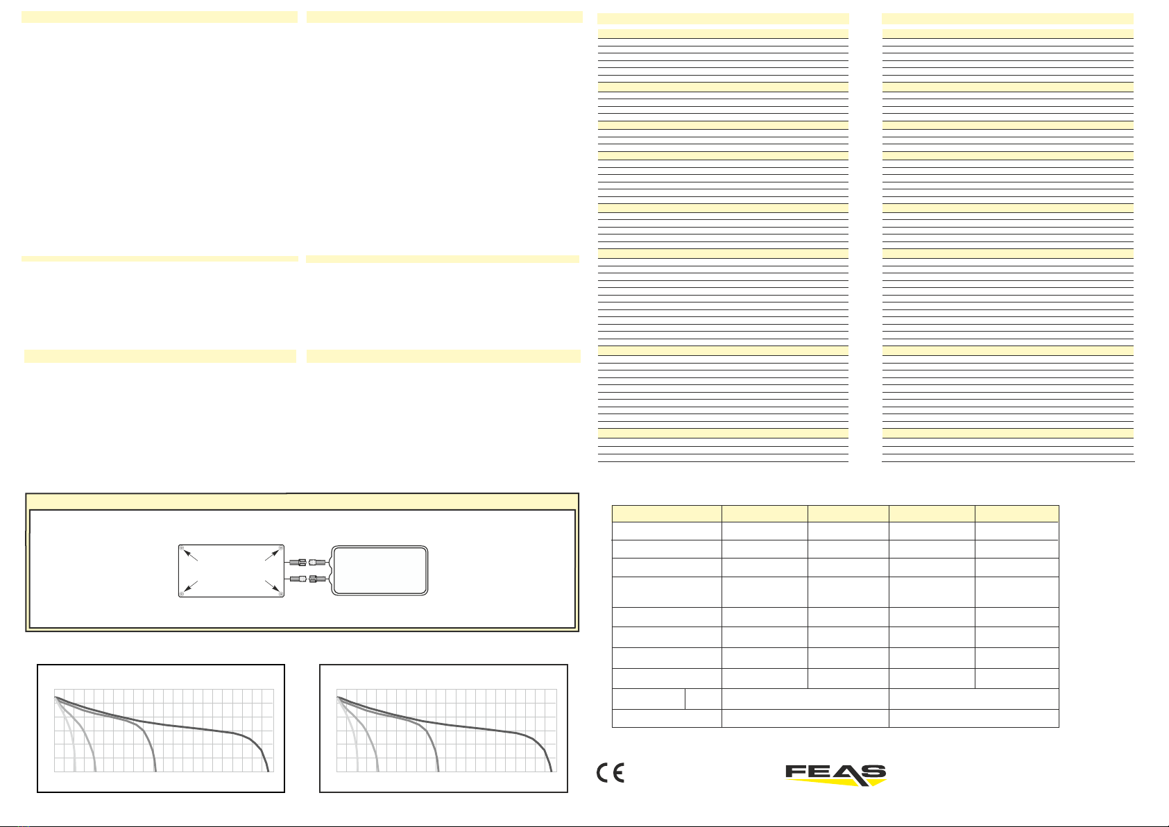
Batteriewechsel / Battery replacment
12 / 24V-Version
Akku
+
-
Hier Inbusschrauben
mit Inbusschlüssel
(SW2) lösen!
15
15
1 CA 0,5 CA 0,2 CA 0,1 CA
14
13
12
11
10
Spannung / Voltage U (V) è
Entladekennlinien bei 20°C - Discharge current diagram at 20°C
LDR5012
0 30 60
1h 90 120
2h 150 180
3h 210 240
4h 270 300
5h 330 360
6h 390 420
7h 450 480
8h 510 540
9h 570 600
10h 630 660
11h
Entladezeit / Discharging period t (min) è
25
26
1 CA 0,5 CA 0,2 CA 0,1 CA
24
23
22
21
20
Spannung / Voltage U (V) è
Entladekennlinien bei 20°C - Discharge current diagram at 20°C
LDR5024
0 30 60
1h 90 120
2h 150 180
3h 210 240
4h 270 300
5h 330 360
6h 390 420
7h 450 480
8h 510 540
9h 570 600
10h 630 660
11h
Entladezeit / Discharging period t (min) è
- konform GmbH
Postfach 1521
D - 22905 AHRENSBURG
Telefon: 04102 - 42082
Telefax: 04102 - 40930
www.feas.de
©2017 ®Stand: 16.08.2017
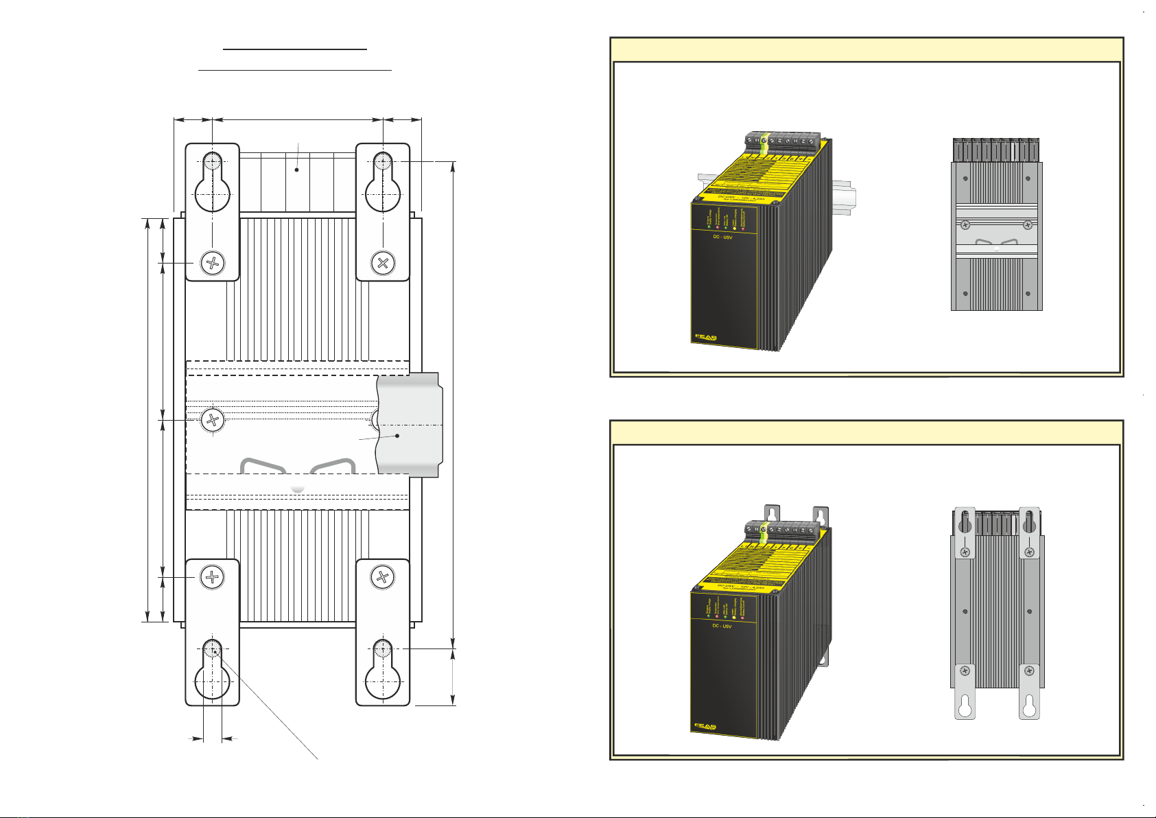
13 mm 13 mm
57 mm
135 mm
6,1 mm
163 mm19 mm
15 mm 15 mm52,5 mm52,5 mm
Geeignet für M6 Schrauben
Suitable for M6 screws
Klemmen / terminals
Hutschiene / rail
Maße Rückseite
Dimensions backside
Montage auf Hutschiene / Mounting on rail
Wandmontage / Wallmounting
Rückseite des Gerätes
backside of the unit
Geeignet für Hutschienenprofil nach DIN 46277
suitable for rail acc. to DIN 46277
Geeignet für M6 Schrauben
Suitable for M6 screws
Rückseite des Gerätes
backside of the unit
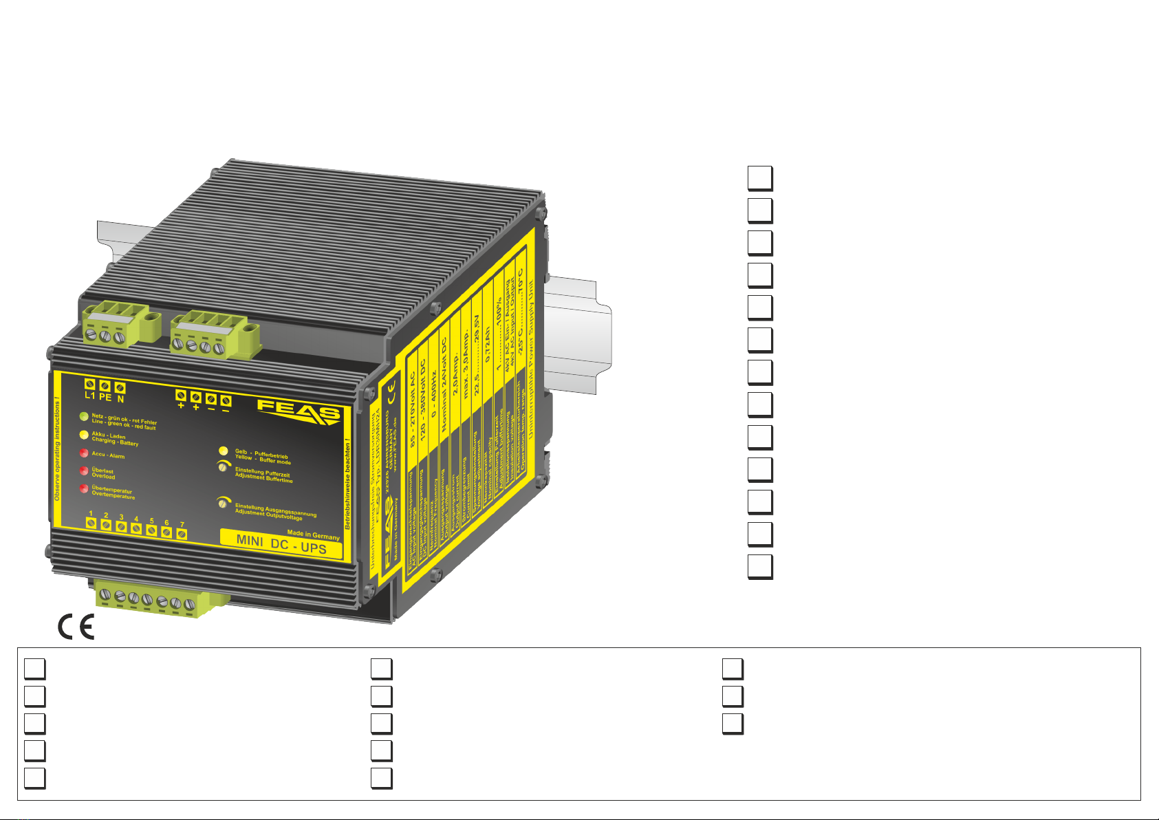
LDR30MH24
Mini DC-USV für die Hutschiene
Art.Nr.: 589960
Relais-Meldung von Netzausfall, Akkumulator-Defekt,
Übertemperatur und Akkumulator-Spannung kritisch
LED-Anzeige für Netzausfall, Übertemperatur und Überlast
Integrierter NiMH-Akkumulator 0,72 Ah (wechselbar)
Pufferung eines Verbrauchers nach Netzausfall
Mikroprozessorgesteuerte Akkumulator-Überwachung und
Ladeanzeige
Ausgang potentialfrei nach VDE0551Schutzkleinspannung PELV (EN 60204), SELV (EN 60950)
Kurzschlussfest, überlast- und leerlaufsicher
Im Pufferbetrieb manuell abschaltbar “Schlafenlegen”
Pufferzeit begrenzbar (1 bis 20 Minuten und unbegrenzt)
Tropentauglich - Gießharzvollverguss
Sicherheit nach VDE, EN, UL und CSA
50% Überlast über längeren Zeitraum möglich
LDR30MH24 for 24V supply
DC
with output buffering
- compliant
Output potential free according to VDE0551
Extra low safety potential PELV (EN 60204),
SELV (EN 60950)
Short circuit, overload and open circuit proof
Manual shut down in buffer mode “sleep mode”
Buffer time terminable (1 up to 20 minutes and unlimited)
Suitable for the tropics - epoxy resin casted
Relay signals for mains failure, battery defect, overtemperature and
battery voltage critical
LED display for mains failure, overtemperature and overload
Safety according to VDE, EN, UL and CSA
50% overload over some time possible
Integrated NiMH accumulator 0.72 Ah (exchangeable)
Buffering of the 24V line at mains failure
DC
Microprocessor controlled battery monitoring and charge status display
WWW.FEAS.de
This manual suits for next models
4
Other FEAS Power Supply manuals

FEAS
FEAS PSU90 User manual

FEAS
FEAS LDR40MH24/12 User manual

FEAS
FEAS LDR8312 User manual

FEAS
FEAS LDR8012-K User manual

FEAS
FEAS PSW7012 User manual

FEAS
FEAS PS5U750130 User manual

FEAS
FEAS LDR8024-RS User manual

FEAS
FEAS LDR8024-RS User manual

FEAS
FEAS LDR40MH24/12 User manual

FEAS
FEAS SNT130-K User manual


Popular Power Supply manuals by other brands


Regulus
Regulus PG 600 SX Installation and operation manual

Autonics
Autonics SPA-400-24 Series product manual

Puls
Puls Dimension CP Series user manual

ITW
ITW Simco-Ion Dual Phase+ Installation and operating instructions

TDK-Lambda
TDK-Lambda HWS ME Series instruction manual

Tagan
Tagan PipeRock TG600-BZ Features & specifications