TECO-Westinghouse F510 Series User manual

OUT of the Box Startup – Overview
This document is intended as a quick start guide to get familiarity with keypad
navigation, changing parameters, and setting the F510 drive up for external
start/stop and external potentiometer signal. Please note this document is not
a substitute for the F510 User Manual and it is important that you reference the
F510 user manual before proceeding.
1Check Nameplate and Connect Input / Output Wiring -
Check the inverter nameplate to insure that the informationagrees with your order.Also insure that the power available is rated
appropriately forthe drive being used.
Secure the Inverter in
a suitable location
DANGER
Do not apply power until all
connections are correct
and secure, and all
protective covers are in
place.
!
Removeprotectivecovers to access
the power terminal blocks. (Refer to
the F510 User Manual for detailed
instructions.)
MOTOR
T1 T2 T3
INPUT POWER
L1 L2 L3
AppropriateInput
Power
3Ø Induction Motor
2Power-up the Inverter, check the Digital Operator
In this step, after the initial power-up you will become familiar with the indications and functions of the Digital Operator.
STEP
STEP
To reverse direction
of motor rotation
swap any two leads
KEYS (8) Description
RUN: RUN Inverter inLocal Mode
STOP: STOP Inverter
LOC/REM: Switches between Local and Remoteoperation
DSP/FUN: Switches between available displays
</RESET: Left Shift: Used to change parameters orvalues, RESET
alarms and faults
ENTER: Used to display the preset value of parameters and to save
changes
Parameters navigation Up, Increase parameters orreference value
Parameters navigation Down, Decreaseparameters or reference value
F510 Control Settings (Factory Default)
RUN/STOP Control: Keypad (RUN / STOP key)
SPEED Control: Keypad (Default 5.00 Hz)
See step 5. to change to RUN/STOP to external switch/contact.
See step 6. to change to external potentiometer control.
Press RUN to start the drive or STOP to stop the drive.
Changing Speed Reference
Press ENTER button and use
to change reference.
Press </RESET button to shift cursor to
the left
Press ENTER button to save
3Ø Input
LCD Display
Run Status
Indicator 8 button
Membrane Keypad
Stop Status Indicator
Fault Status
Indicator
Forward
Direction
Status Indicator
ReverseDirection
Status Indicator
External Reference
Indicator
External Sequence
Indicator
Fref Ref
12-16=005.00Hz
Monitor
12-17=000.00Hz
12-18=0000.0A
Fref Ref
12-16=005.00Hz
Monitor
12-17=000.00Hz
12-18=0000.0A
Note: For 1Ø Input use terminals L1- L3 NOTE:Properly check the
GROUNDCONNECTION
Ground
DANGER
!
Check Motor Rotation
3
STEP
This test is to be performed solely from the inverter keypad. Apply power to
the inverter after all the electrical connections have been made and protective
covers have been re-attached. At this point, DO NOT RUN THE MOTOR, the
keypad should display as shown below in Fig. 1a and the speed reference
5.00 Hz should be blinking.
Solid
Next press the RUN key. The motor should now be operating at low speed
running in forward (clockwise) direction. The keypad should display as shown
above in Fig. 1b and the speed reference 5.00 Hz should be solid. Next press
STOP key to stop the motor.
Fig. 1a Fig. 1b
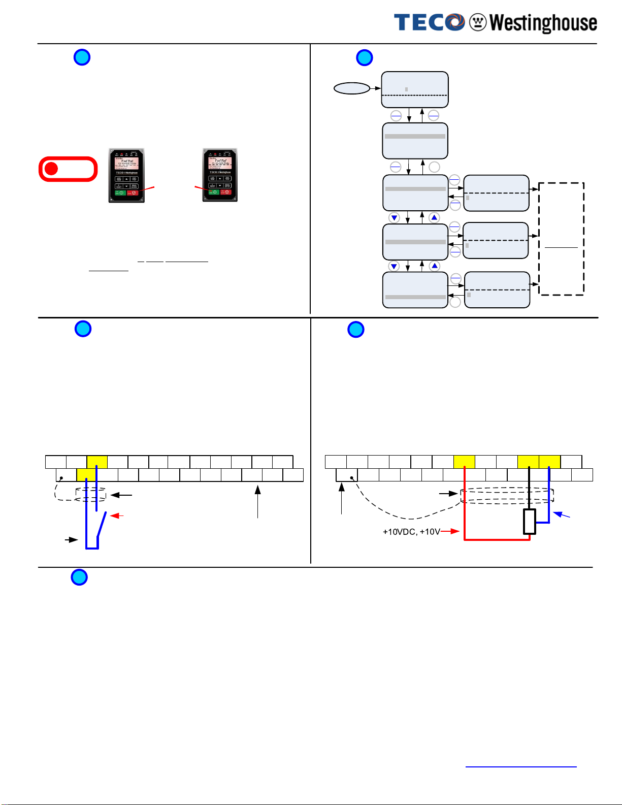
How to Change Parameters
4
STEP
Important: Motor rotation and direction only applies to standard AC
motors with a base frequency of 60Hz. For 50Hz or other frequency AC
motors please set V/F pattern in group 01 before running the motor.
If the motor rotation is incorrect, power down the inverter. After the power
has been turned OFF, wait at least ten minutes until the charge indicator
extinguishes completely before touching any wiring, circuit boards or
components.
Using Safety precaution, and referring to step 1 exchange any two of the three
output leads to the motor (T1, T2 and T3). After the wiring change, repeat this
step and recheck motor direction.
POWER ON
DS P
FUN
RE AD
ENTE R
RE AD
ENTE R
RE AD
ENTE R
RE AD
ENTE R
Monitor Freq Ref
12-17=000.00Hz
12-18=0000.0A
12-16=005.00Hz
Control Method
Edit 00-00
0V/F
(0~4)
<0>
Motor Direction
0Forward
(0~1)
<0>
Run Source
0 Digital Op
(0~4)
<1>
DS P
FUN
Edit 00-01
Edit 00-02
DS P
FUN
DS P
FUN
DS P
FUN
Group
01 V/F Pattern
02 Motor Parameter
00 Basic Func.
PARA 00
-00 Control Method
-01 Motor Direction
-02 RunSource
PARA 00
-00 Control Method
-01 Motor Direction
-02 RunSource
PARA 00
-00Control Method
-01 Motor Direction
-02 RunSource
Parameter
Group
Selection
Mode
Parameter
Group
Mode
Parameter
Edit Mode
DS P
FUN
Press ▼or ▲
key to edit
parameter value,
and press
READ/ENTER
key to save the
change.
Stop
Light
Solid
Run light flashing until
desired frequency set in
12-16 is reached after
which light turns solid.
Afterpower-up set parameter 00-05=1 (Speed Reference from Control Terminals).
Using an external potentiometer for speed control
6
STEP
Default Setting: The F510 by default uses the keypadfor frequency reference,
followinstructionsbelow to use a remote reference (external potentiometer).
Instructions to change to remote reference:
- Powerdown thedrive,wait10 min.
- Remove theprotective covers (See F510 UserManual) and make the
connections as shown below in Fig. 2b.
- Verifythat all connections are secure, replace covers and power-up the drive.
Do not apply power until all connections are correct and secure, and all
protective covers are in place.
After power-up set parameters 00-02=1 (Run Source from Control Terminals).
Default Setting: The F510 by default uses the keypadto run andstop, follow
instructions below to change toa remotestart/stop (maintained contact/switch).
Instructions to change toremote run/stop:
- Powerdown thedrive,wait10 min.
- Remove theprotective covers (See F510 UserManual) and make the
connections as shown below in Fig. 2a.
- Verifythat all connections are secure, replace covers and power-up the drive.
Using Remote Run/Stop (Maintained Contact/Switch)
Do not apply power until all connections are correct and secure, and all
protective covers are in place.
5
STEP
Potentiometer
1 ~ 5K Ohm (½ W) Fig. 2b
Common
/24VG
Fig. 2a
Terminal representation for 230V: 1 ~ 3 HP, 460V: 1 ~ 3HP
(See section 3.3 ofthe instruction manual for other sizes) Terminal representation for 230V: 1~ 3 HP, 460V: 1 ~ 3 HP
(See section 3.3 ofthe instruction manualfor other sizes)
Start / Stop Switch
(Maintained)
Forward Command/FWD Control
Terminals / User
Terminals
Connect shield to
control ground terminal
S(+) S(-) S1 S3 S5 24V +10V MT GND GND AI1 AI2
E 24VG S2 S4 S6 SF1 SG SF2 PO PI AO1 AO2
Connect shield to
control ground
terminal
Common/0V, GND
Analog
Input AI1
S(+) S(-) S1 S3 S5 24V +10V MT GND GND AI1 AI2
E24VG S2 S4 S6 SF1 SG SF2 PO PI AO1 AO2
Control Terminals /
UserTerminals
Motor Nameplate Data (Parameter 02-01)
The motor rated current is set at the factory based on the inverter model. Enter the motor rated current from the motor nameplate if it does not match the value
shown in parameter 02-01.
Setting range: Varies by model.
Frequently Used Parameters
7
STEP
Acceleration and Deceleration Time (Parameter 00-14, 00-15)
Acceleration and Deceleration times directly control the system dynamic response. In general, the longer the acceleration and deceleration time, the slower the
system response, and the shorter time, the faster the response. An excessive amount of time can result in sluggish system performance while too short of a time
may result in system instability.
Using Keypad for Speed Reference (Parameter 00-05)
To use the keypad set parameter 00-05 to 0.
The default values suggested normally result in good system performance for the majority of general purpose applications. If the values need to be adjusted,
caution should be exercised, and the changes should be in small increments to avoid system instability.
00-14 Acceleration time 1
00-15 Deceleration time 1
These parameters set the acceleration and deceleration times of the output frequency from 0 to maximum frequency and from maximum frequency to 0.
Factory Reset (Parameter 13-08)
To reset all parameters back to factory default set parameter 13-08 to 9.
F510 Startup Guide V1.6 –01/23/20
For the complete F510 parameter listing and descriptions, refer to the F510 Instruction manual on our website www.tecowestinghouse.com
Other manuals for F510 Series
2
Other TECO-Westinghouse DC Drive manuals


Popular DC Drive manuals by other brands


Graham
Graham 1703 Series Installation, operation and maintenance manual

Electro-Voice
Electro-Voice ID60D-8 Specifications

Parker
Parker Compax3H C3H1xxV4 Series installation manual

eldoLED
eldoLED LINEARdrive 720D quick start guide

Nidec
Nidec Unidrive M100 Installation sheet

ITOH DENKI
ITOH DENKI POWER MOLLER HBM-604BN manual


