DANGER
!
Check Motor Rotation
3
STEP
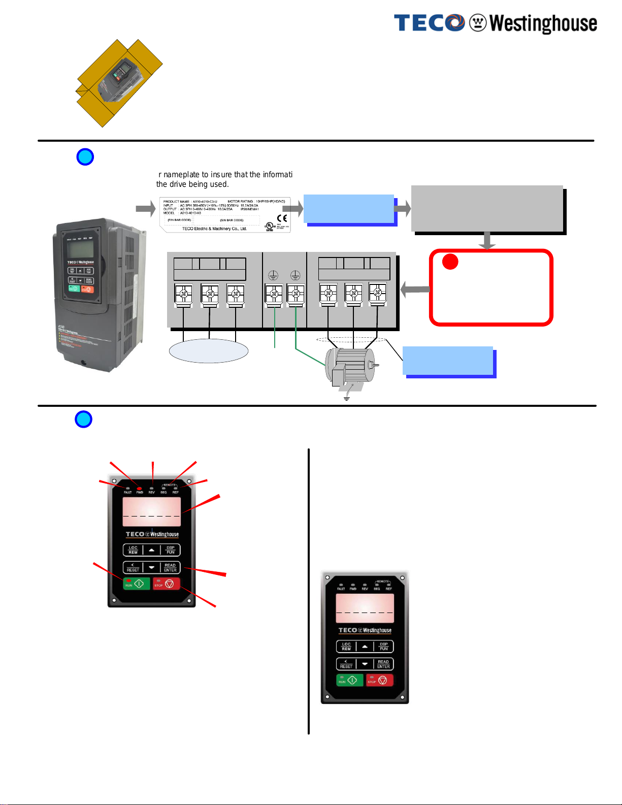
This test is to be performed solely from the inverter keypad. Apply powerto
the inverterafter all the electrical connections have been madeand protective
covers havebeen re-attached. At this point, DO NOT RUN THE MOTOR, the
keypad should displayasshown below in Fig. 1a and the speed reference
5.00 Hz shouldbe blinking.
Solid
Next press the RUN key. The motorshouldnow be operating at low speed
running in forward (clockwise) direction. The keypad should display as shown
above in Fig. 1b and thespeedreference5.00 Hz should besolid. Next press
STOP key tostop the motor.
Fig. 1a Fig. 1b
How to Change Parameters
4
STEP
Important: Motor rotation and direction only appliesto standard AC
motors with a base frequency of 60Hz. For 50Hz or other frequency AC
motors please set V/Fpatternin group 01 before running the motor.
If themotor rotation is incorrect, power down the inverter. After the power
has been turned OFF, wait at least ten minutes untilthecharge indicator
extinguishes completely before touching any wiring, circuit boards or
components.
Using Safetyprecaution, and referring tostep 1exchange anytwoof the three
output leads to the motor (T1, T2 and T3). Afterthe wiring change, repeat this
step and recheck motor direction.
POWER ON
DSP
FUN
READ
ENTER
READ
ENTER
READ
ENTER
READ
ENTER
Monitor
Freq Ref
12-17=000.00Hz
12-18=0000.0A
12-16=005.00Hz
Control Method
Edit 00-00
0 V/F
(0~4)
<0>
Motor Direction
0 Forward
(0~1)
<0>
Run Source
0 Digital Op
(0~4)
<1>
DSP
FUN
Edit 00-01
Edit 00-02
DSP
FUN
DSP
FUN
DSP
FUN
Group
01 V/F Pattern
02 Motor Parameter
00 Basic Func.
PARA 00
-00 Control Method
-01 Motor Direction
-02 Run Source
PARA 00
-00 Control Method
-01 Motor Direction
-02 Run Source
PARA 00
-00 Control Method
-01 Motor Direction
-02 Run Source
Parameter
Group
Selection
Mode
Parameter
Group
Mode
Parameter
Edit Mode
DSP
FUN
Press ▼or ▲
key to edit
parameter value,
and press
READ/ENTER
key to save the
change.
Stop
Light
Solid
Run light flashing until
desiredfrequency set in
12-16 is reached after
which light turns solid.
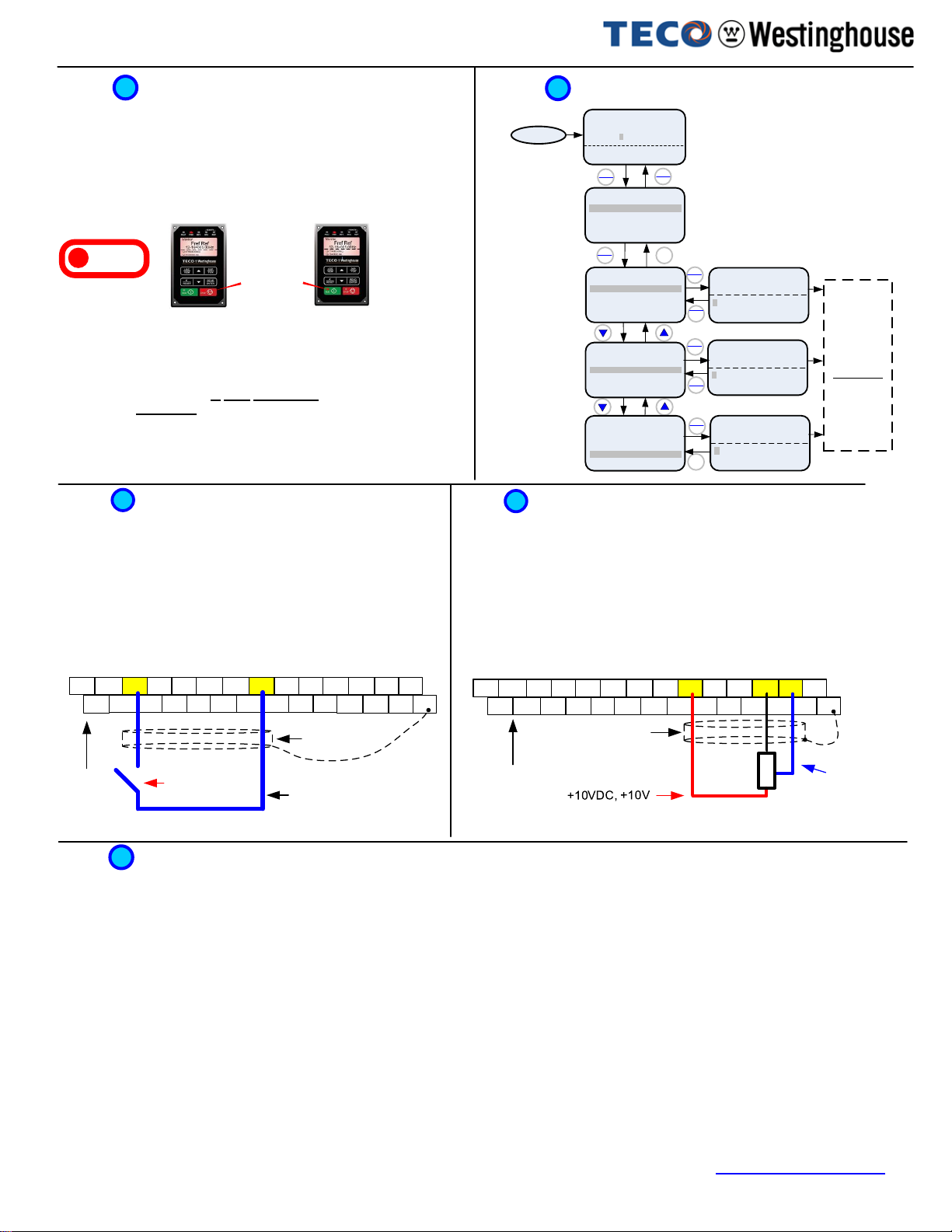
S(+) S(-) S1 S3 S5 S7 24VG -10V+10V GND AI1 AI2
24V GND
DO1 DOG S2 S4 S6 S8 SG POSF2 PI AO2 E
SF1 AO1
After power-up set parameter 00-05=1 (Speed Reference from Control Terminals).
Using an external potentiometer for speed control
6
STEP
Default Setting: The A510 by default uses the external terminal for frequency reference. If
changed to controlled by keypad already, follow instructions below to use a remote
reference (external potentiometer).
Instructions to change to remote reference:
- Power down the drive, wait 10 min.
- Remove the protective covers (See A510s User Manual) and make the
connections as shown below in Fig. 2b.
- Verify that all connections are secure, replace covers and power-up the drive.
Do not apply power until all connections are correct and secure, and all protective
covers are in place.
After power-up set parameters 00-02=1 (Run Source from Control Terminals).
Default Setting: The A510 by default uses the external terminal to run and stop, If
changed to controlled by keypad already, follow instructions below to change to a remote
start/stop (maintained contact/switch).
Instructions to change to remote run / stop:
- Power down the drive, wait 10 min.
- Remove the protective covers (See A510s User Manual) and make the
connections as shown below in Fig. 2a.
- Verify that all connections are secure, replace covers and power-up the drive.
Using Remote Run/Stop (Maintained Contact/Switch)
Do not apply power until all connections are correct and secure, and all protective
covers are in place.
5
STEP
Fig. 2b
Fig. 2a
Forward
Command / FWD
Control
Terminals /
User
Terminals
Connect shield to
control ground
terminal
Common
/24VG
Control Terminals /
UserTerminals
Connect shield
to control
ground terminal
Potentiometer
1 ~ 5K Ohm (½ W)
Common/0V, GND
Analog
Input AI1
S(+) S(-) S1 S3 S5 S7 24VG -10V+10V GND AI1 AI2
24V GND
DO1 DOG S2 S4 S6 S8 SG POSF2 PI AO2 E
SF1 AO1
Terminal representations for 230: 1~2 HP, 460V: 1-3HP
(seesection 3.9 of the instruction manual for other sizes) Terminal representations for 230: 1~2 HP, 460V: 1-3HP
(see section 3.9 of the instruction manual for other sizes)
Motor Nameplate Data (Parameter 02-01)
The motor rated current is set at the factory based on the inverter model. Enter the motor rated current from the motor nameplate if it does not match the value
shown in parameter 02-01.
Setting range: Varies by model.
Frequently Used Parameters
7
STEP
Acceleration and Deceleration Time (Parameter 00-14, 00-15)
Acceleration and Deceleration times directly control the system dynamic response. In general, the longer the acceleration and deceleration time, the slower the
system response, and the shorter time, the faster the response. An excessive amount of time can result in sluggish system performance while too short of a time
may result in system instability.
Using Keypad for Speed Reference (Parameter 00-05)
To use the keypad set parameter 00-05 to 0.
The default values suggested normally result in good system performance for the majority of general purpose applications. If the values need to be adjusted,
caution should be exercised, and the changes should be in small increments to avoid system instability.
00-14 Acceleration time 1
00-15 Deceleration time 1
These parameters set the acceleration and deceleration times of the output frequency from 0 to maximum frequency and from maximum frequency to 0.
Factory Reset (Parameter 13-08)
To reset all parameters back to factory default set parameter 13-08 to 2.
A510 Startup Guide V1.04 –01/23/20
For the complete A510 parameter listing and descriptions, refer to the A510 Instruction manual on our website www.tecowestinghouse.com