Tecsis EZE30 Owner's manual

Operating manual/Programmer`s manualOperating manual/Programmer`s manual
EZE30
Digital load cell ampilfier with analogue output
and setpoints
||
Pressure |||
Temperature Switch ServiceForce
BE 948 a

CONTENTS
Page 2
Wiring Diagram and Key Functions Page 3
Quick Setup and Calibration using Weights Page 4
1. Enable Zero Button / Calibrate Zero point Page 8
2. Setup and calibrate the Span Function / Display Input Signal in mV/V Page 10
3. Setup the Display (Over/Under Range Limits, steps size & decimal point, Logic I/O Status) Page 12
4. Filter Setting and No Motion Page 14
5. Analogue Output (4-20mA) Settings Page 16
6. Logic Inputs 1,2&3 Page 17
7. Logic Outputs 1,2&3 Page 19
8. Data Communication Settings Page 20
Error Codes / Return to Factory Settings Page 21
Communication Protocol Page 22
Examples
Calibration Procedure using weights Page 23
Calibration Procedure from known load cell mV/V sensitivities - Multiple active load cells Page 24
Single active load cell plus pivot Page 25
Programmers manual Annex A
Quick Setup and Calibration using the load cell mV/V Sensitivities Page 6
Filter Setting Tables & Update Rates (Number of Readings Averaged) Page 15
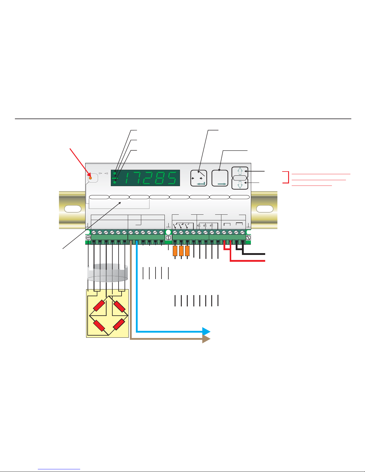
- SIGNAL
SHIELD
- EXCITATION
- SENSE
+ EXCITATION
+ SENSE
+SIGNAL
Load cell connections*
11-25
VDC
4-20mA
Output
Ground
RS422/485
Comms.
Recessed Enable Switch
(Enables changes to be made to important parameters.
Must be pressed AFTER entering ‘Set up’ mode but
before attempting to change parameters 1.1 to 1.3,
2.1 to 2.3 and 3.1 to 3.3)
Centre of Zero LED (±0.5d)
Minus Sign (>4 Digits ONLY)
Unit in Net Mode LED
Up Key
Down Key
Press either Key for more
than 3 seconds to enter
the ‘Set up’ Mode
Zero Key - Sets new zero (if enabled). Reverts to calibrated zero
if the button is held down for more than 3 seconds.
Switches unit back to ‘Gross’ mode if a tare has been set.
Acts as the ‘Enter’ key in the ‘Set-up’ Mode.
Tare Key - Puts unit into ‘Net’ mode. When inside
‘Set-up’ Menu this key moves the menu
back one step. Also moves ‘Digit Selected’
to the right when inside sub menus.
‘Set-up’ menu structure
0
Net
Digital Amplifier + Setpoint EZE30
+++ ++
--- 0
0
Exc Sen Inp Inp Sen Exc
Load cell 5Vdc < 80mA Isolated
Logic Outputs
Isolated
Logic Inputs
Isolated
Power 11 -25Vdc
++
--
Rx Rx Tx Tx
RS422/485
Gnd
0-20mA
Io
CL out
SET UP
1.Zero
1.0/allow>0<
2.Calibrate
3.Set mV/V
2.Span
1.Set cal ´n´
2.Calibrate
3.Set mV/V
4.Disp.mV/V
3.Display
1.o/u limits ´n´
2.
3.
4.Logic stats
Step*´n´
Dec.point
4.Filter
1.f Hz
2.Algorithm
3.Update rate
4.Motion´n´
cut
5.CLout
1.4mA=´n´
2.20mA=´n´
3.Base
4.Test I mA
6.Input 1/2/3
1.Assign Key
2.
3.
4.Test
7.Outp. 1/2/3
1.SPoint´n´
2.Hyst. ±´n´
3.Base
4.Test
8.Datacom.
1.Baud rate
2.422/485
3.Address
4.Auto trnsm.
T
T
T
0
T
12
3
4
1 2 3 com 1 2 3 com
depress
to
change
Logic input
Logic output
123
123
Logic Input 1 (+)
Logic Input 2 (+)
Logic Input 3 (+)
Logic Inputs (0V)
Logic Inputs
Receive +
Logic Outputs (0V)
Transmit +
Transmit -
Receive -
Logic Output 1 (+)
LOAD
Logic Output 2 (+)
LOAD
Logic Output 3 (+)
LOAD
*Please note that if you have a 4
wire cable from your junction box
or load cell to the EZE30, you
MUST put in additional links
between the Exc+ and Sen+
terminals and between the Exc-
and Sen- terminals. Otherwise the
display will show Err 5 (faulty load
cell connection)
Page 3

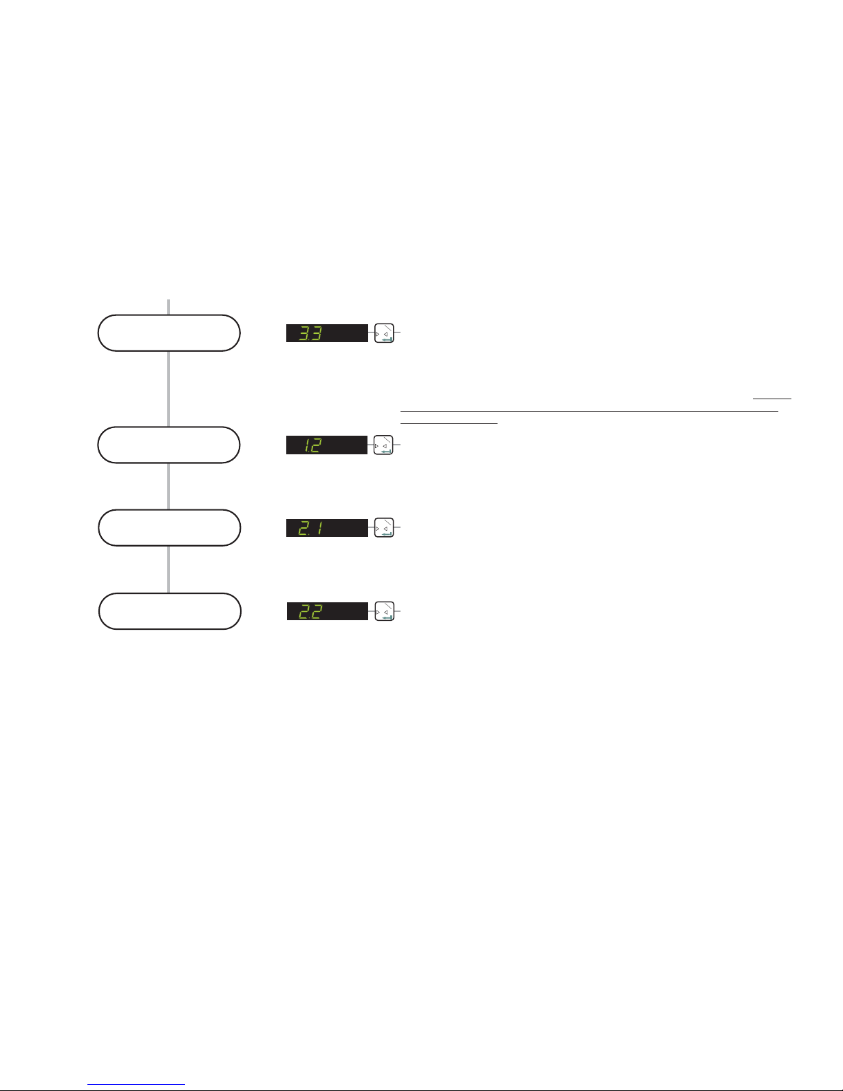
QUICK SET UP AND CALIBRATION USING WEIGHTS
Press the UP or DOWN key for more than 3 seconds to enter the Set-up Menu
Enter the
Setup menu SET UP
3
4Please note that if you wish to change any values in these sections, you have to first
press the recessed enable switch (top left corner of unit)
0T
1
Set the Display
Upper Limit SET THE DISPLAY OVER RANGE LIMIT. (MAXIMUM VALUE +99,999)
Use this menu point to define the display maximum value. If the displayed weight
exceeds this maximum, the display will then show over range (dashes at the top of
the display). This can be useful to indicate when a weight value is outside a normal
range. Use the UP/DOWN & MOVE RIGHT keys to set the maximum display value
and store by pressing the enter key. Factory default value 10,000. Please note that
the zero button is limited to ±2% of the display maximum value. See section 1.1
Zero Button Enable for more details
0T
1
Set the Display
Lower Limit SET THE DISPLAY UNDER RANGE LIMIT. (MINIMUM VALUE -99,999).
Use this menu point to define the display minimum value. If the displayed
weight drops below this minimum, the display will then show under range
(dashes at the bottom of the display) This can be useful to indicate when a
weight value is outside a normal range. Use the UP/DOWN & MOVE RIGHT
keys to set the minimum display value and store by pressing the enter key.
Factory default value -9,999.
0T
1
Set the Display
Step Size SELECT THE DISPLAY STEP SIZE. (1, 2, 5, 10, 20, 50, 100, 200 or 500)
Use this menu point to select the display step size. The minimum display step
size is 1 [Factory default] up to a maximum step size of 500. If for example you
select a display step size of 50, the display will show 000, 050, 100, 150 etc as
the weight value increases. Using higher step sizes will give a more stable
weight display but with a lower resolution. Use the UP or DOWN key to select
the required display step size. Press the enter key to store.
QUICK SET UP AND CALIBRATION USING WEIGHTS (Continues on the next page)
(Also see calibration examples on page 22)
Page 4
QUICK SET UP AND CALIBRATION USING WEIGHTS (Continued)
SELECT THE DECIMAL POINT POSITION ON THE DISPLAY (0, 0.0, 0.00,
0.000 or 0.0000)
Use the UP or DOWN key to set the required decimal point position on the
display. The factory default is no decimal place [0]. The maximum number of
places after the decimal point is four [0.0000]. Please note that this parameter
should be set before the span calibration value [menu 2.1] is entered. Setting
or moving the decimal point position after calibration will not alter the
display resolution
0T
1
Set the Decimal
Point position
0T
1
Calibrate the
Zero point CALIBRATE OR ADJUST THE ZERO POINT (CONVENTIONAL WEIGHING
SYSTEM)
Use this menu point to store a new calibration zero. The display will show the
actual input signal in mV/V. Ensure that the weighing system is at zero or has
no load on it. Pressing the Enter key will store the new zero.
0T
1
Define the Span
Calibration weight
DEFINE THE SPAN CALIBRATION WEIGHT
This menu point defines the span calibration value. If you intend to calibrate the
span conventionally using weights, you need to enter the value of the span test
weight you intend to apply here. Use the UP/DOWN & MOVE RIGHT keys to
enter the span test weight. For example if you intend to calibrate with 3000 kg
of weight (stepping in 1 kg steps with no decimal places) then enter 3000 here.
0T
1
Calibrate the Span CALIBRATE THE SPAN (CONVENTIONAL WEIGHING SYSTEM)
Use this menu point to calibrate the span using weights. Apply the span test
weight [the test weight value is defined in menu 2.1] to the weighing system.
The display will show the actual signal from the weighing system .
Press the Enter key to store the new span value.
in mV/V
Page 5

QUICK SET UP AND CALIBRATION USING THE LOAD CELL mV/V SENSITIVITY
QUICK SET UP AND CALIBRATION USING LOAD CELL mV/V (Continues on the next page)
Press the UP or DOWN key for more than 3 seconds to enter the Set-up Menu
Enter the
Setup menu SET UP
3
4Please note that if you wish to change any values in these sections, you have to first
press the recessed enable switch (top left corner of unit)
0T
1
Set the Display
Upper Limit SET THE DISPLAY OVER RANGE LIMIT. (MAXIMUM VALUE +99,999)
Use this menu point to define the display maximum value. If the displayed weight
exceeds this maximum, the display will then show over range (dashes at the top of
the display). This can be useful to indicate when a weight value is outside a normal
range. Use the UP/DOWN & MOVE RIGHT keys to set the maximum display value
and store by pressing the enter key. Factory default value 10,000. Please note that
the zero button is limited to ±2% of the display maximum value. See section 1.1
Zero Button Enable for more details
0T
1
Set the Display
Lower Limit SET THE DISPLAY UNDER RANGE LIMIT. (MINIMUM VALUE -99,999).
Use this menu point to define the display minimum value. If the displayed
weight drops below this minimum, the display will then show under range
(dashes at the bottom of the display) This can be useful to indicate when a
weight value is outside a normal range. Use the UP/DOWN & MOVE RIGHT
keys to set the minimum display value and store by pressing the enter key.
Factory default value -9,999.
0T
1
Set the Display
Step Size SELECT THE DISPLAY STEP SIZE. (1, 2, 5, 10, 20, 50, 100, 200 or 500)
Use this menu point to select the display step size. The minimum display step
size is 1 [Factory default] up to a maximum step size of 500. If for example you
select a display step size of 50, the display will show 000, 050, 100, 150 etc as
the weight value increases. Using higher step sizes will give a more stable
weight display but with a lower resolution. Use the UP or DOWN key to select
the required display step size. Press the enter key to store.
(Also see calibration examples on page 23)
Page 6

QUICK SET UP AND CALIBRATION USING LOAD CELL mV/V (Continued)
SELECT THE DECIMAL POINT POSITION ON THE DISPLAY (0, 0.0, 0.00,
0.000 or 0.0000)
Use the UP or DOWN key to set the required decimal point position on the
display. The factory default is no decimal place [0]. The maximum number of
places after the decimal point is four [0.0000]. Please note that this parameter
should be set before the span calibration value [menu 2.1] is entered. Setting
or moving the decimal point position after calibration will not alter the
display resolution
0T
1
Set the Decimal
Point position
0T
1
Calibrate the
Zero point CALIBRATE OR ADJUST THE ZERO POINT.(CONVENTIONAL WEIGHING
SYSTEM)
Use this menu point to store a new calibration zero. The display will show the
actual input signal in mV/V. Ensure that the weighing system is at zero or has
no load on it. Pressing the Enter key will store the new zero.
0T
1
Enter the weighing
system capacity
DEFINE THE SPAN CALIBRATION VALUE.
This menu point defines the span calibration value. If you intend to calibrate the
span using the mV/V readings from the load cell certificates, you should enter
the total load cell capacity here. So for example if you have a weighing system
consisting of 3 off 2000 kg load cells you should enter 6000 (3 x 2000) here.
Use the UP/DOWN & MOVE RIGHT keys to enter the total load cell capacity.
0T
1
Enter the weighing
system mV/V value CALIBRATE THE SPAN FROM THE LOAD CELL mV/V READING
If you are calibrating the weighing system without weights, use this menu point
to enter the mV/V value for the weighing system. The weighing system mV/V
value can be derived from the load cell test data. Normally a test data
certificate is provided with each load cell stating amongst other things, the
Output at Rated Load (ORL) in mV/V. In single load cell applications the
weighing system mV/V value will be the load cell ORL value. In applications
using more than one load cell, the weighing system mV/V value will be the
average of the individual load cells ORLs. Normally load cells used in multi-cell
applications have matched or rationalized ORLs typically 2 or 3 mV/V for
example. So if you have 4 load cells in your system, each 1000 kg capacity
with ORLs of 2 mV/V then the weighing system capacity will be 4000 kg at 2
mV/V. Use the UP/DOWN & MOVE RIGHT keys to enter the weighing system
ORL reading in mV/V. The reading should be in the format x.xxxx e.g 2.0000 if
the ORL is 2 mV/V exactly. The corresponding weighing system capacity should
be entered in menu point 2.1
Page 7
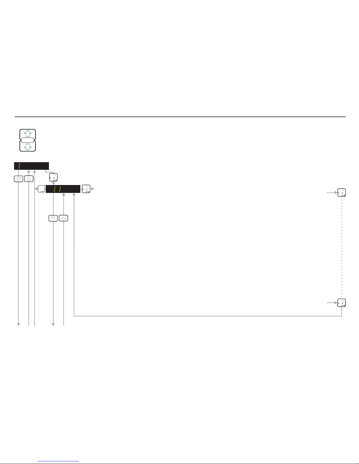
ENTERING THE SETUP MENU
Press the UP or DOWN key for more than 3 seconds to enter the Set-up Menu
SET UP
ENABLE ZERO BUTTON / SET ZERO TRACK RANGE / CALIBRATE ZERO POINT
ENABLE ZERO BUTTON / CALIBRATE ZERO POINT (Continues on next page)
0T
1
0T
1
T
T
T
2
3
3
3
4
4
4
ZERO BUTTON ENABLE (± 20% of DISPLAY MAX) / ZERO TRACK RANGE (± 255 d).
Use this menu point to enable or disable the zero button and to set the zero track range. If this parameter is set to
0 then the zero button and the zero tracking will be disabled. If this parameter is set between 1 and 255, the zero
button will be enabled and the zero track range will be equal to the number set. Use the UP/DOWN & MOVE
RIGHT keys to set the zero track range and store by pressing the enter key. Factory default value 00001.
In the normal weighing mode, the zero button will set a new zero providing that the displayed weight value is less
than ± 20% of the maximum display value (see Menu 3.1 o). So if for instance, the maximum display value is set
to 10,000 [Factory Default] the maximum display value that can be set to zero using this button is ± 20% of 10,000
i.e. ± 2000 display counts. If you try to set a new zero which is greater than ± 20% of the display maximum you will
see the error message ‘Err 2’ on the display. To overcome this problem you can either re-calibrate the zero using
Menu 1.2 or 1.3 or you can increase the display maximum (Menu 3.1.o) to allow higher offsets to be corrected.
If this parameter is set between 1 and 255 (not 0) then the zero tracking will also be enabled. The value set will be
equivalent to the zero track range (plus and minus around zero). The zero tracking will work on the no load or zero
value of the weighing system to bring it back to exactly 0. If for instance the no load value or zero of the weighing
system comes back to 5d when unloaded (due to product build up in the weigh hopper for instance), the zero
tracking will automatically reduce this zero offset back to zero providing that the zero is stable (no motion) and is
inside the zero track range. The no load output will be reduced at a fixed rate of 0.4 d/second until the value
reaches 0. The value of d is equal to the display step size.
0T
1
If you wish to change any values in these sections, you have to first press the recessed enable switch (top left corner of unit)
0T
1
Page 8

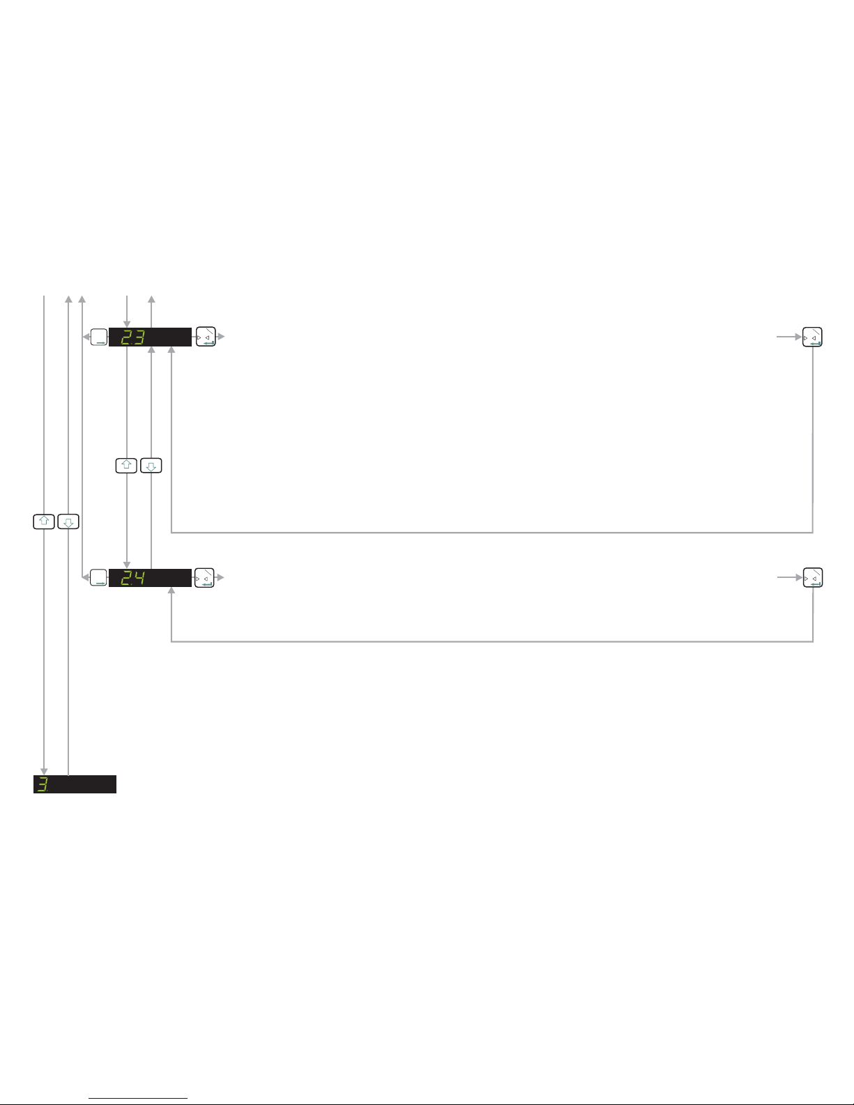
SET UPAND CALIBRATE SPAN FUNCTION / DISPLAY INPUT SIGNAL IN mV/V - See Next Page
ENABLE EX MODE (WIDER TOLERANCE BAND ON SENSE INPUT)
Use this menu point to enable (E - on) a wider tolerance on the sense input. This will
allow the EZE30 to be used with electrical safety barriers (hazardous area
applications) which reduce the sense voltage. If the sense voltage is too low ‘Err 5’
(load cell fault) will be displayed. There are 2 possible settings E - off (factory default)
standard sense input tolerance or E - on wider sense input tolerance enabled.
0T
1
0T
1
ENABLE ZERO BUTTON / CALIBRATE ZERO POINT (Continued)
CALIBRATE THE ZERO POINT FROM THE LOAD CELL mV/V READING
Use this menu point to enter a mV/V value at which you want the weighing system to read zero. Use the
UP/DOWN & MOVE RIGHT keys to set the mV/V reading. Pressing the Enter key will store this value. The
weighing system will now read zero at this mV/V reading.
0T
1
T
T
T
2
0T
1
3
4
3
4
3
4
3
4
CALIBRATE OR ADJUST THE ZERO POINT.(CONVENTIONAL WEIGHING SYSTEM)
Use this menu point to store a new calibration zero. The display will show the actual input signal in mV/V
from the load cells. Ensure that the weighing system is at zero or has no load on it. Pressing the Enter key
will store the new zero.
0T
1
T
T
T
2
0T
1
0T
1
T
T
T
2ENABLE STORING OF TARE VALUE (NON-VOLATILE)
Use this menu point to enable (t - on) the storing of the tare value in memory. This
will prevent the loss of the tare value in the event of a power failure. There are 2
possible settings t - off (factory default) tare storing not enabled or t - on tare storing
enabled.
0T
1
0T
1
T
T
T
2
T
T
T
2
Page 9

SET UPAND CALIBRATE SPAN / DISPLAY INPUT SIGNAL IN mV/V
0T
1
3
4
0T
1
T
T
T
2
3
4
0T
1DEFINE THE SPAN CALIBRATION VALUE.
This menu point defines the span calibration value. If you intend to calibrate the span conventionally using
weights, you need to enter the value of the span test weight you intend to apply here. Use the UP/DOWN &
MOVE RIGHT keys to enter the span test weight. For example if you intend to calibrate with 3000 kg of
weight (stepping in 1 kg steps with no decimal places) then enter 3000 here. If however, you intend to
calibrate with 3000 kg and you want to step in 0.1 kg steps you must enter 30000 here. The decimal point
can be added later in menu 3.3.
If you intend to calibrate the span using the mV/V readings from the load cell certificates, you should enter
the total load cell capacity here. Use the UP/DOWN & MOVE RIGHT keys to enter the total load cell
capacity. For example if you have a weighing system consisting of 3 off 2000 kg load cells and you want to
display in 1 kg steps with no decimal places, you should enter 6000 (3 x 2000) here. If however you want to
display 6000 kg in 0.1 kg steps you should enter 60000 here. The decimal point can be added later in menu
3.3.
T
T
T
2CALIBRATE THE SPAN. (CONVENTIONAL WEIGHING SYSTEM)
Use this menu point to calibrate the span using weights. Apply the span test weight [the test weight value is
defined in menu 2.1] to the weighing system. The display will show the actual signal from the weighing
system . Press the Enter key to store the new span value.in mV/V
0T
1
0T
1
3
4
If you wish to change any values in these sections, you have to first press the recessed enable switch (top left corner of unit)
SET UPAND CALIBRATE SPAN /DISPLAY INPUT SIGNAL IN mV/V (Continues on next page)
Page 10
DISPLAY THE INPUT SIGNAL IN mV/V
Use this function to view the raw signal coming from the load cells into the EZE30. The display shows the
load cell signal directly in mV/V. This can be useful when either commissioning or fault finding.
0T
1
T
T
T
2
0T
1
CALIBRATE THE SPAN FROM THE LOAD CELL mV/V READING
If you are calibrating the weighing system without weights, use this menu point to enter the mV/V value for
the weighing system. The weighing system mV/V value can be derived from the load cell test data. Normally
a test data certificate is provided with each load cell stating amongst other things, the Output at Rated Load
(ORL) in mV/V. In single load cell applications the weighing system mV/V value will be the load cell ORL
value. In applications using more than one load cell, the weighing system mV/V value will be the average of
the individual load cells ORLs. Normally load cells used in multi-cell applications have matched or
rationalized ORLs typically 2 or 3 mV/V for example. So if you have 4 load cells in your system, each 1000
kg capacity with ORLs of 2 mV/V then the weighing system capacity will be 4000 kg at 2 mV/V.
Use the UP/DOWN & MOVE RIGHT keys to enter the weighing system ORL reading in mV/V. The reading
should be in the format x.xxxx e.g 2.0000 if the ORL is 2 mV/V exactly. The corresponding weighing system
capacity should be entered in menu point 2.1
0T
1
T
T
T
2
0T
1
3
4
SET UP THE DISPLAY - See Next Page
SET UPAND CALIBRATE SPAN /DISPLAY INPUT SIGNAL IN mV/V (Continued)
3
4
Page11
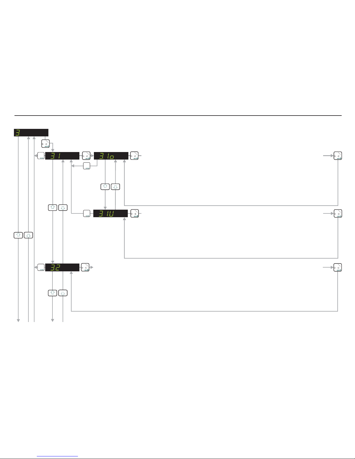
SET UP THE DISPLAY (Continues on next page)
0T
1
T
T
T
2
0T
1
0T
1
T
T
T
2
0T
1
SET THE DISPLAY OVER RANGE LIMIT. (MAXIMUM VALUE +99,999)
Use this menu point to define the display maximum value. If the displayed weight
exceeds this maximum, the display will then show over range (dashes at the top of the
display). This can be useful to indicate when a weight value is outside a normal range.
Use the UP/DOWN & MOVE RIGHT keys to set the maximum display value and store by
pressing the enter key. Factory default value 10,000. Please note that the zero button is
limited to ±2% of the display maximum value. See section 1.1 Zero Button Enable for
more details
0T
1
T
T
T
2SET THE DISPLAY UNDER RANGE LIMIT. (MINIMUM VALUE -99,999).
Use this menu point to define the display minimum value. If the displayed weight
drops below this minimum, the display will then show under range (dashes at the
bottom of the display) This can be useful to indicate when a weight value is outside a
normal range.
Use the UP/DOWN & MOVE RIGHT keys to set the minimum display value and store by
pressing the enter key. Factory default value -9,999.
0T
1
3
4
3
4
3
4
T
T
T
2
0T
1SELECT THE DISPLAY STEP SIZE. (1, 2, 5, 10, 20, 50, 100, 200 or 500)
Use this menu point to select the display step size. The minimum display step size is 1 [Factory default] up
to a maximum step size of 500. If for example you select a display step size of 50, the display will show 000,
050, 100, 150 etc as the weight value increases. Using higher step sizes will give a more stable weight
display but with a lower resolution.
Use the UP or DOWN key to select the required display step size. Press the enter key to store.
0T
1
3
4
SET UP THE DISPLAY (OVER/UNDER RANGE LIMITS, STEP SIZE & DECIMAL POINT, LOGIC I/O STATUS)
If you wish to change any values in these sections, you have to first press the recessed enable switch (top left corner of unit)
Page 12

T
T
T
2
FILTER SETTINGS & NO MOTION - See Next Page
LOGIC INPUTS & OUTPUT STATUS (SHOW CONTINUOUSLY)
When this parameter is selected the status of the inputs and outputs are continuously
displayed on the main weight display. No weight values are displayed in this mode. This
can be useful when commissioning the system as you can see the exact status of the
inputs and outputs continuously.
0T
1
LOGIC INPUTS & OUTPUTS STATUS (NO INDICATION)
When this parameter is selected there will be no indications on the main display of the
status of the logic inputs and outputs. The weight value is shown continuously
irrespective of the logic inputs and outputs status [Factory Default]
0T
1
0T
1
3
4
LOGIC INPUTS & OUTPUT STATUS (ONLY SHOW WHEN I/O STATE CHANGES)
When this parameter is selected, there will be a momentary indication on the main
display of the logic input/output status ONLY when the status changes. The weight value
display is temporarily disabled whilst the logic input/output status is shown momentarily.
The display then reverts back to displaying the weight value. This can be useful when
commissioning the system as you can see the exact status of the inputs and outputs as
and when they change.
0T
1
3
4
SET UP THE DISPLAY (Continued)
3
4
T
T
T
2
0T
1
0T
1
SELECT THE DECIMAL POINT POSITION ON THE DISPLAY (0, 0.0, 0.00, 0.000 or 0.0000)
Use the UP or DOWN key to set the required decimal point position on the display. The factory default is no
decimal place [0]. The maximum number of places after the decimal point is four [0.0000]. Please note that
this parameter should be set before the span calibration value [menu 2.1] is entered. Setting or moving the
decimal point position after calibration will not alter the display resolution
3
4
Page 13

ANALOGUE OUTPUT SETTINGS - See Page 16
FILTER SETTINGS & NO MOTION
0T
1
SELECT THE TYPE OF LOW PASS FILTER REQUIRED. (TYPE Fir [Mode 1] or IIr [Mode 0])
Use the UP/DOWN keys to select the type of filter used. Type IIR should be used where heavy damping is
required. Type FIR should be used where high speed is required. Default setting IIR. See Filter Level (FL)
versus Cut off Frequency tables on the next page.
0T
1
T
T
T
2
0T
1
0T
1
T
T
T
2SET THE STABILISATION TIME. (RANGE 0 - 65535)
Use the UP/DOWN & MOVE RIGHT keys to set the time in milliseconds within which
the weight value displayed has to remain within the no motion range, for the weigh to
be considered ‘stable’. Default value 1000
0T
1
3
4
0T
1
0T
1
T
T
T
2SELECT THE LOW PASS FILTER CUT OFF FREQUENCY. (RANGE 0 - 8)
Use the UP/DOWN keys to select the cut off frequency required. A setting of 0 will disable the filter in both FIR &
IIR modes. A setting of 1 provides the least filtering and a setting of 8 provides the most. Default setting 4. See
Filter Level (FL) versus Cut off Frequency tables on the next page.
3
4
3
4
SELECT THE NUMBER OF FILTERED READINGS AVERAGED (RANGE 0 - 7)
Use the UP or DOWN key to select the number of readings from the IIR or FIR filter that will be averaged.
Default setting 0 (off). See Update Rates versus Number of Samples table on the next page.
0T
1
T
T
T
2
0T
1
3
4
T
T
T
2
0T
1
0T
1
T
T
T
2
SET THE NO MOTION RANGE. (RANGE 0 - 65535)
Use the UP/DOWN & MOVE RIGHT keys to set the no motion range. Fluctuations in
weight values inside this range will be considered as ‘stable’. Default value 1
0T
1
3
4
Page 14

FILTER SETTINGS TABLES & UPDATE RATES (NUMBER OF READINGS AVERAGED)
Filter Setting
1
2
3
4
5
6
7
8
3dB Cut-off
Frequency in Hz
18
8
4
3
2
1
0.5
0.25
Settling time to
0.1% in ms.
55
122
242
322
482
963
1923
3847
Damping in dB
At 300Hz
57
78
96
104
114
132
149
164
Update Rate in
Samples/sec.
600
600
600
600
600
600
600
600
MENU 4.1-4.2 FILTER TYPE IIR (MODE 0) SECOND ORDER GAUSSIAN LOW
Filter Setting
1
2
3
4
5
6
7
8
3dB Cut-off
Frequency in Hz
19.7
9.8
6.5
4.9
3.9
3.2
2.8
2.5
Settling time to
0.1% in ms.
47
93
140
187
233
280
327
373
20dB Damping
@ frequency Hz
48
24
16
12
10
8
7
6
40dB Damping
@ frequency Hz
64
32
21
16
13
11
9
8
Damping in dB
in Stopband
>90
>90
>90
>90
>90
>90
>90
>90
Stopband in Hz
>80
>40
>26
>20
>16
>13
>11
>10
Update Rate in
Samples/sec.
600
300
200
150
120
100
85.7
75
MENU 4.1- 4.2 FILTER TYPE FIR (MODE 1) COMBINATION LOW PASS
Update Rates
No. of Samples
0
1
2
4
3
8
4
16
6
64
7
128
5
32
1
2
MENU 4.3 UPDATE RATE - DEFINES HOW MANY MEASUREMENTS ARE USED TO CALCULATE AN AVERAGE
This section refers to Menu points 4.1 - 4.3.
Setting the filter level to 0 will disable the filters
in either modes (0 or 1). The Gaussian filter type
IIR (mode 0) filter level 4 is the factory default.
This provides a slower response with a high
level of damping. The FIR filter type provides
better response where high speed is required.
Both types of filter can be enhanced further by
using the UR parameter Menu 4.3 to average
between 1 (UR=0) and 128 (UR=7)
measurements.
Page 15

LOGIC INPUTS - See Next Page
ANALOGUE OUTPUT (4-20 mA) SETTINGS
0T
1
3
4
0T
1
0T
1
T
T
T
2SET THE WEIGHT VALUE AT WHICH 4 mA IS SENT
Use the UP/DOWN & MOVE RIGHT keys to set the weight value at which 4 mAis sent. This typically will be set to
zero, so that when the display reads zero weight, 4 mA will be sent down the analogue output. If you want the
analogue output to run between 0 mA and 20 mA, you will need to calculate what the 4 mA value will be and store
it here. To do this take the difference between the weight value at 20 mAand the weight value at 0 mAand divide it
by the 20 and multiply by 4. For example if the analogue output is 0 - 20 mA for 0 - 1000 kg then the 4 mAvalue will
be 1000/20*4 = 200.
3
4
0T
1
T
T
T
2TEST MODE FOR THE CURRENT OUTPUT (Range 0mA - 21mA)
Use the UP or DOWN & MOVE RIGHT key to set a current value in mA, which will be sent down the
analogue output, independent of the load applied to the weighting system. If values below 0mA are selected
the DAS will send its minimum value (0mA) until a value within its normal range is selected. Similarly if
values above 21mA are selected then the DAS will send its maximum value (21mA) until a value within its
normal range is selected.
0T
1
SET THE WEIGHT VALUE AT WHICH 20 mA IS SENT.
Use the UP/DOWN & MOVE RIGHT keys to set the weight value at which 20 mA is sent. Typically this will
be set to the weight value at which you want 20 mA to be sent down the analogue output.
0T
1
T
T
T
2
0T
1
3
4
SET THE ANALOGUE OUTPUT BASE (groS, nEt [Default], PEA, AUEr, HoLd, PP, UALL, dISP, oFF)
groS
nEt PEA
AUEr HOLd
oFF
Use the UP or DOWN key to set which parameter the analogue output will follow : - the analogue
output follows the Gross value: - the analogue output follows the Net value : - the analogue output
follows the Peak value: - the analogue output follows the Average value:
-
the analogue output is switched off.
- the analogue output
follows the Hold value: - the analogue output follows the Peak to Peak value: - the analogue
output follows the Valley value: - the analogue output follows the value shown on the display:
PP UALL
dISP
0T
1
T
T
T
2
0T
1
3
4
Page 16


LOGIC INPUTS
0T
1
T
T
T
2
3
4
3
4
0T
1
0T
1SET THE FUNCTION OF LOGIC INPUT 1. (RANGE 00 - 14)
Use the UP/DOWN keys to set the function of logic input 1.
.00 - No function. .01 - Remote Zero. .02 - Remote Tare. .03 - Up Arrow Key. .04 - Down
Arrow Key. .05 - Trigger the average function. .06 - Display average value. .07 - Display
peak value. .08 - Clear peak, valley and hold values. .09 - Display hold value. .10 - Display
peak to peak value. .11 - Display valley value. .12 - Lock keyboard. .13 - Trigger hold
function. .14 - Set tare and reset/clear the peak/valley/hold values. Please ensure that
this logic input is NOT high when setting or changing the function of this logic input.
0T
1
T
T
T
2
3
4
T
T
T
2NOT IN USE
T
T
T
2
NOT IN USE
T
T
T
2
READ THE STATUS OF LOGIC INPUT 1. (In1 0 or In1 1)
Read the status of Logic Input 1. If the input is high the display reads In1 1. If the input is
low the display reads In1 0. In order for the status of this logic input to be read correctly,
you must set the function (as defined in section 6.1.1) to 0 [No function]
T
T
T
2
3
4
3
4
0T
1
LOGIC INPUTS (Continues on next page)
0T
1
0T
1
0T
1
3
4
T
T
T
2
3
4
SET THE FUNCTION OF LOGIC INPUT 2. (RANGE 00 - 14)
Use the UP/DOWN keys to set the function of logic input 2.
.00 - No function. .01 - Remote Zero. .02 - Remote Tare. .03 - Up Arrow Key. .04 - Down
Arrow Key. .05 - Trigger the average function. .06 - Display average value. .07 - Display
peak value. .08 - Clear peak, valley and hold values. .09 - Display hold value. .10 - Display
peak to peak value. .11 - Display valley value. .12 - Lock keyboard. .13 - Trigger hold
function. .14 - Set tare and reset/clear the peak/valley/hold values. Please ensure that
this logic input is NOT high when setting or changing the function of this logic input.
Page 17

LOGIC OUTPUTS - See Next Page
LOGIC INPUTS (Continued)
READ THE STATUS OF LOGIC INPUT 2. (In2 0 or In2 1)
Read the status of Logic Input 2. If the input is high the display reads In2 1. If the input is
low the display reads In2 0. In order for the status of this logic input to be read correctly,
you must set the function (as defined in section 6.2.1) to 0 [No function]
T
T
T
2T
T
T
2
0T
1
NOT IN USE
T
T
T
2
0T
1
0T
1
0T
1
T
T
T
2
3
4
T
T
T
2NOT IN USE
T
T
T
2
NOT IN USE
T
T
T
2
READ THE STATUS OF LOGIC INPUT 3. (In3 0 or In3 1)
Read the status of Logic Input 3. If the input is high the display reads In3 1. If the input is
low the display reads In3 0. In order for the status of this logic input to be read correctly,
you must set the function (as defined in section 6.3.1) to 0 [No function]
T
T
T
2
0T
1
T
T
T
2
T
T
T
2
NOT IN USE
3
4
3
4
3
4
3
4
SET THE FUNCTION OF LOGIC INPUT 3. (RANGE 00 - 14)
Use the UP/DOWN keys to set the function of logic input 3.
.00 - No function. .01 - Remote Zero. .02 - Remote Tare. .03 - Up Arrow Key. .04 - Down
Arrow Key. .05 - Trigger the average function. .06 - Display average value. .07 - Display
peak value. .08 - Clear peak, valley and hold values. .09 - Display hold value. .10 - Display
peak to peak value. .11 - Display valley value. .12 - Lock keyboard. .13 - Trigger hold
function. .14 - Set tare and reset/clear the peak/valley/hold values. Please ensure that
this logic input is NOT high when setting or changing the function of this logic input.
Page 18

DATACOMS - See Next Page
LOGIC OUTPUTS
0T
1
0T
1
T
T
T
2
0T
1
0T
1
0T
1
SET WEIGHT VALUE AT WHICH LOGIC OUTPUT 1 SWITCHES
Use the UP/DOWN and MOVE RIGHT keys to set the weight value
(SETPOINT) at which logic output1 changes state (switches on/off)
SET WHETHER LOGIC OUTPUT 1 SWITCHES ON OR OFF
Use the UP/DOWN keys to set whether logic output 1 switches on or
off at the set point.
0T
1
0T
1
T
T
T
2
T
T
T
2
T
T
T
2SET THE HYSTERESIS VALUE ON THE SETPOINT FOR LOGIC OUTPUT 1
Use the UP/DOWN and MOVE RIGHT keys to set the hysteresis value on logic output 1
setpoint.
0T
1
0T
1
T
T
T
2
0T
1
0T
1
SET LOGIC OUTPUT 1 BASE (groS, nEt, PEA, AUEr, HOLd, PP, UALL, Error, oFF)
groS nEt
PEA
Use the UP or DOWN key to define the parameter, based on which Logic Output 1 will
operate : - operates when the Gross value reaches or exceeds the setpoint : -
operates when the net value reaches or exceeds the setpoint. - operates when the
peak value reaches or exceeds the setpoint. - operates when the average value
reaches or exceeds the setpoint. - operates when the Hold value reaches or
exceeds the setpoint. - operates when the peak to peak value reaches or exceeds
the setpoint. - operates when the Valley value reaches or exceeds the setpoint.
- operates when Err 4 or Err 5 occurs. - Logic Output 1 is disabled.
AUEr
HOLd
PP
UALL
Error oFF
0T
1
T
T
T
2
0
T
1
TEST MODE FOR LOGIC OUTPUT 1 (0 - Off, 1 - ON)
Use the UP or DOWN key to switch on (1) or off (0) Logic Output 1.
3
4
3
4
3
4
3
4
3
4
AS PER SECTIONS 7.1 BUT FOR LOGIC OUTPUT 2
T
T
T
2
AS PER SECTIONS 7.1 BUT FOR LOGIC OUTPUT 3
T
T
T
2
3
4
3
4
Page 19
Table of contents
Other Tecsis Amplifier manuals


