Tecsun Xiegu G90 User manual

www.tecsunradios.com.au
Xiegu G90
Panel Layout and Major Function Controls for the Sight Impaired.
Virtually all the buttons and rotary controls in the G90 are dual function. Hence this is a lengthy
document. These instructions refer to firmware build 1.74 (004)
Front Panel Controls
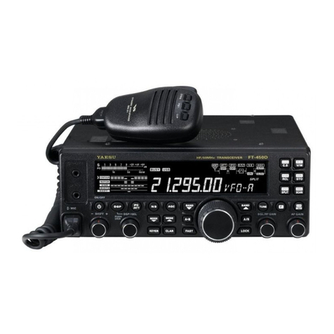
The G90 has a square LCD display centrally located on the front panel. To the left of the display
there are 2 rotary and one push button control. The push button is the Power On/OFF. Press
this button for 1 second to turn the radio ON. You will hear a beep to confirm this. To turn
the radio OFF, do the same thing-no beep confirmation. When the radio is ON, momentarily
pressing the power button disabled the display, saving power consumption. Pressing any key
turns the display back on.
The two rotary controls to the left of the display are Volume and Multifunction. The uppermost
control is Volume. Depressing the volume control, mutes the speaker and sends the audio to
the headphone socket mounted on the left hand side panel (it is the uppermost 3.5mm socket).
There are many functions that can be controlled through the use of this button. Most are
duplicated by other means described in this guide. As most of the functions require a sighted
person to set the parameters, I have only included those functions that are not duplicated
elsewhere.
SQUELCH. Press the Multifunction control for 1 second. Rotate the Tuning knob until SQL
level is displayed. Press the SAVE button (second from the left of the 5 button group below the
display), the display now returns to normal. Momentarily press the Multifunction button until
the filter bandwidth display is shown without the white end traces, then rotate the Multifunction
control to turn on the squelch function and use the Tuning control to set the level.
TUNING CONTROL. The largest rotary knob on the front panel is used to tuning the frequency
to which the transceiver is to be operated. Repeatedly depressing the tuning knob sequences the
frequency step through the following: 10Hz, 100Hz, 1KHz, 10KHz and 100KHz. Depress
the tuning control for 1 second to enter the RIT adjustment. Rotate the control clockwise for
positive values and anticlockwise for negative values. The total range is 500KHz either side of
the centre frequency.
To access TX POWER adjust function use must be made of a 4 button group located on the
right hand edge of the front panel. The first (top) button is Tune, the second is TX power
(marked POW), the third button is Key and the forth button is Lock.

www.tecsunradios.com.au
To put the transceiver in the Tune ready mode, depress the Tune button momentarily. To activate
the auto tuner, depress the Tune button for 1 second.
To adjust the TX power level press the POW button (second down from the top of the group
of 4 buttons on the RHS) once, then rotate the Tuning control to the appropriate level. Power
increments are 1 Watt. Press the TUNE button twice to enter the SWR Threshold setting.
Rotate the Tuning control to select a threshold from 1.8 to 3.6. Press the Tuning control to end
this process. Depress the POW button for more than 1 second, to initiate an SWR scan of the
connected antenna (with the tuner out of circuit). Press the VM button to stop the scan.
Press the KEY button once to set the key speed, and rotate the tuning control for the appropriate
speed. Depress the KEY button twice to access the M/L/R and choose the appropriate setting
by rotating the tuning control. Depress the KEY button three times to access the mode function
and rotate the tuning control to select A or B. Press the KEY button four times to set QSK
ON/OFF using the tuning control. Press the KEY button five times to access the QSK time
and adjust using the tuning control. Press the KEY button six times to set the Ratio and adjust
it using the tuning control.
Press the LOCK button repeatedly to step through the 5 brightness settings for the display. Press
the Lock button for 1 second to lock all controls. Depress the Lock button again for 1 second
to unlock all controls.
To adjust the VOX settings, first press the function button (left hand button of the group of
three to the left top of the display), then press the Volume control once to select VOX ON/
OFF function. Rotate the main tuning dial to toggle between ON and OFF. Press the volume
control twice to select VOX gain and rotate the Volume control to set the level. Press the Volume
control three times to select the anti-VOX and rotate the Volume control to set the level. Press the
Volume control four times to select the VOX delay and rotate the Tuning control to set the level.
After a period of 12 seconds where no changes are made to any VOX settings (or indeed any of
the functions controlled by the FUNC button), the receiver automatically saves the settings and
reverts to receive mode.
To access the FFT Scale and Spectrum reference level, first press the FUNC button then press
the Lock button within 10 seconds. This reveals a spectrum display amplitude scale allowing
selection of auto then 2-10, 10 being the lowest sensitivity. After about 15 seconds of inactivity
access to this function disappears. To make any subsequent changes first press the FUNC
button to turn it OFF, then press it again to turn it ON and then select the lock key to access
the menu. Pressing the Lock key a second time allows access to the display Averaging function
and any value can be set from 1-10.

www.tecsunradios.com.au
Along the horizontal top edge of the front panel there are 4 buttons. The left had 2 buttons are
Mode up and Mode down. Repeatedly pressing either of these buttons steps through the modes
available: AM, LSB, USB, CW, CWR, and NBFM (if this option is fitted) in the desired direction.
The next 2 buttons are frequency band UP and frequency band DOWN. Repeatedly pressing
either button steps the transceiver through the available bands: 1.8Mhz, 3.5Mhz, 5.2Mhz, 7Mhz,
10Mhz, 14Mhz, 18Mhz, 21Mhz, 24Mhz, and 28Mhz in the desired direction.
Located below the LCD display is a horizontal grouping of 5 buttons. These are also dual
function buttons. The most left hand button is preamp and attenuator. Pressing this button
steps through preamp ON, attenuator ON, and neither activated.
The second button from the left is the CMP button. Pressing this button toggles the compressor
ON or OFF. The second function of this button is the digital filter low frequency setting. First
press the Function button (left hand button of the group to the right of the top of the display),
then press the CMP button to set the lower frequency of the digital filter.
The third button is the NB button press this button once and use the Tuning control to toggle
between ON and OFF. Press the NB button twice to select the NB level and use the Tuning
control to adjust (range is 0 to 10). Press the NB button three times to select the NB (blanking
pulse) width and use the Tuning control to select a value from 1 to 10.
The forth button is the AGC button. Press this button to step through S (slow AGC), F (fast
AGC), A (automatic), and no AGC. Settings S and A can result in reduced volume from the
receiver, so don’t panic. Press the AGC button for 1 second to access the RF gain control and
use the Tuning control to change the value 90-100%).
The fifth button is the VFO/Memory function (toggles between the 2). There is no second
function for this button. This allows the user to toggle between the VFO and a frequency
previously stored in memory.
Of the 3 buttons located immediately adjacent to the display, (the first button is the FUNC
button already discussed) the second button from the left is the MW/MC button (memory write
and memory clear functions). There are 63 memory positions available. Pressing the button
activates the memory write function. Ensure memory position 0 is used first. Select a desired
frequency to be entered into memory. Press the MW/MC button, rotate the tuning dial to select
the memory position, then press the MW/MC button again to store.
The third button is the VFO A/B control. Pressing this button, toggles between VFO A and B.
Pressing the function button first allows the user to copy the contents of VFO A into VFO B.

www.tecsunradios.com.au
To exit from any function depress the main tuning knob momentarily.
Side Panel Controls
The left hand side of the transceiver has a panel housing two 3.4mm sockets. The upper socket
is for connecting headphones and the lower socket is for connecting the UBS to 3.5mm
programming adaptor, used to upgrade the firmware to the control head and base unit.
The right hand side of the transceiver has an RJ45 socket for connecting the microphone.
Rear Panel Connections
On the left hand side of the rear panel there is an SO239 antenna socket. To the right of that
there is a group of 3 x 3.5mm sockets. From left to right they are labelled key, COMM and I/Q.
Further to the right hand side there is an 8 pin MiniDIn socket for connecting accessories and
at the far right there is the keyed DC input socket. It is not possible to connect the DC power in
reverse using the power lead supplied, as one pin is round and the other square. Below the DC
input socket there is an earth connection for vehicle bonding etc.
Microphone Controls
The microphone used for the G90 is generic and is obviously used for other (non Xiegu)
transceivers.
The microphone button layout can be divided in half, those that fall above a noticeable groove
that runs horizontally across the face, and those below. Above the groove there are 3 rows each
having 3 columns.
Row 1: The top left hand button marked LOCK has no function. The next button in the top
row marked TUNE activates all tuner functions as previously described in this guide. The third
button in the top row, marked XFC appears to have no function.
Row 2: The left-hand button on the second row is the FREQUENCY UP button and increments
the operating frequency in 100hz steps (or whatever step has been set prior by repeatedly
depressing the Tune control). The second button on the second row is the V/M button and
toggles between the VFO frequency and any programmed memory channel selected. The third
button on the second row is marked MW and appears to have no function.
Row 3: The left hand button is the FREQUENCY DOWN button, the middle button on
this row is marked F1 and controls the preamp and attenuator, toggling between preamp on,
attenuator on and neither on. The third button is marked F2. It is another configurable button
with no apparent function in this firmware build.

www.tecsunradios.com.au
Below the horizontal groove, there are 4 rows each of 4 buttons.
Row 1: Labelled 1, 2, 3, these buttons actually control the operating band. So the left hand
button selects 1.8Mhz, the second button selects 3.5Mhz, the third button selects 7Mhz, the
forth button is the Mode button and steps through all available modes in the sequence listed in
the front panel controls section of this guide.
Row 2: Labelled 4, 5, 6. From left to right, these buttons select 10MHz, 14MHz, 18MHz and
FIL (no apparent function)
Row 3: Labelled 7,8, 9 these buttons select 21MHz, 24MHz, 28 MHz and something called
GENE (no apparent function).
Row 4: Labelled “.”, 0 and CE, are also marked 50MHz, 144MHz and 430MHz (not for this
transceiver). The last button on the RHS is the F-INP ENT and is the frequency input and enter
button. Let’s call it the ENTER button.
To enter a frequency directly from the microphone, press the ENTER button (bottom right hand
corner of the microphone), then the sequence of digits that make up the frequency. For example,
to enter 7045KHz, press ENTER then 7.045 (the decimal point is required) then ENTER. So,
14100 KHz is entered as ENTER 14.100 ENTER.
There may be other functions available now and in future firmware builds, not covered in this
guide.
If you find something that isn’t covered and should be, please let us know at Tecsun Radios
Australia.
Table of contents
