Tectrix Climbmax 150 User manual
•
•
C/imbMax
MADE
IN
U.S.A.
Everyone
Should
Be
This
Well
Built
THIS
MANUAL,
(INCLUDING
PART
NUMBERS),
APPLIES
TO
THE
'INSTITUTIONAL
STYLE'
CUMBMAX,
SERIAL
NUMBER
166190
AND
Up,
MANUFACTURED
JULY
1993
OR
LATER.
FOR
OPERATION
AND
PART
NUMBER
INFORMATION
FOR
CUMBMAXMODEL
150
(SERIAL
NUMBERS
PRIOR
TO
166190)
REFER
TO
THE
CUMBMAX
MODEL
150
OWNERS
MANUAL
(part
number
03001)
.
Page
1

Table
of
Contents
1.
Assembly
Instructions
4
2.
Setup
Mode
7
3.
Test
Mode
10
MAINTENANCE
4.
Cleaning
11
5.
Drive
Cable
/
Clevis
Bearing
&
Bolt
Replacement
11
6.
Pedal/Cable
Clevis
Lubrication
11
7.
Clutch
Bearing,
Chain,
Crank
Arm
&
Parallel
Shafts
Lubrication
12
8.
Friction
Belt
Replacement
/
Switch
Ends
13
9.
Pedal
Bearing
Inspection
13
TROUBLESHOOTING
GUIDE
10.
'Can't
Slow
Down'
or
'Control
Lost
14
11.
'No
Slack"
17
12.
'No
Brake'
17
13.
'Memory
Lost'
18
14.
A
Numeral
Appears
In
The
Interval
Display
18
15.
Some
LED's
(lights)
Are
Out
On
The
Display
And
There
Is
No
Beep
When
The
Power
Switch
Is
Turned
On
19
16.
All
LED's
(lights)
Are
Out
On
The
Display
And
There
Is
No
Beep
When
The
Power
Switch
Is
Turned
On
19
17.
Reset
Problem
20
18.
A
Key
On
The
Display
Console
Doesn't
Work
21
19.
Pedal
Squeak
21
20.
A
Pedal
Doesn't
Return
To
The
Top
or
A
Pedal
Won't
Go
Down
21
21.
No
Speed
Control
And
No
Error
Message
Is
Displayed
22
22.
Speed
Control
is
Jerky
or
Varies
Speed
22
23.
The
ClimbMax
Won't
Accelerate
To
Top
Speed
23
24.
Cannot
Select
Group
Race
24
PART
REPLACEMENT
25.
Cover
26
26.
Motor
Assembly
27
27.
Slack
Switch
Adjustment
28
28.
Friction
Belt
Replacement
28
29.
Power
Board
Assembly
28
30.
Display
Console
29
31.
Display
Cable
30
32.
RPM
Assembly
:.:
31
33.
Switch
Plate
Assembly
31
34.
Spring
/
Drive
Cable
Replacement
32
35.
Flywheel
Assembly
33
36.
Crank
/
Pedal
Removal
From
Frame
34
37.
Crank
Arm
Assembly
34
38.
Parallel
Arm
Assembly
35
39.
Pedal
Assembly
36
40.
Transmission
Assembly
37
Page
2
•
41.
FIGURES
40
Description
Paqe#
1
Attaching
the
Hand
Rail
Upright
40
2
Attaching
the
Hand
Rails
41
3
Connecting
the
Display
Cable
42
4
Power/Communications
Connectors
43
5
Brake
and
Motor
Assembly
44
6
Parallel
Arm
Assembly
45
7
Spring
Cable
Routing
46
8
Flywheel
Assembly
47
9
Crank
Arm
Assembly
48
10
Pedal
Assembly
49
11
Transmission
Assembly
50
12
Display
Overlay
51
13
Display
Board
Component
Layout
52
14
Display
Board
Schematic
(page
1
of
2)
53
15
Display
Board
Schematic
(page
2
of
2)
54
•
16
Power
Board
Assembly
55
17
Power
Board
Schematic
56
•
Page
3

1.
ASSEMBLY
INSTRUCTIONS
The
ClimbMax
is
quite
easy
to
assemble
and
should
take
around
30
minutes
to
complete.
It
will
require
the
following
common
tools:
1/4"
Allen
Wrench,
3/16"
Allen
Wrench,
Medium
Phillips
Screwdriver
(#2)
7/16"
socket
and
ratchet
1/2"
socket
and
ratchet
Unpacking
your
new
ClimbMaJC
Remove
the
Chassis
base
from
the
pallet
by
removing
the
clamps
and
screws
(use
the
7/16"
socket
and
ratchet).
Remove
all
the
parts
from
the
box
and
check
that
they
are
all
present.
CAUTION:
Do
not
at
any
time
lean
the
display
console
upright
tube
up
on
its
end.
The
display
ribbon
cable
could
be
damaged.
Parts
List
#
Part
Name
Part
#
atv
1
Main
Chassis
Base
(WHT,
BLK,
GRAY)
Color
1
2
Hand
Rail
Upright
1
3
Hand
Rails
(WHT,
BLt<,
GRAY)
Color
2
Ship
Kit
(Contains
the
Following)
1
4
Right
Hand
Rail
Clamp
53003
1
5
Left
Hand
Rail
Clamp
53006
1
6
5/16"-18
X
2"
Socket
Screws
41011
2
7
5/16"
Flat
Washers
53017
2
8
5/16"
Lock
Washer
53018
2
9
1/4"-20
X
1/14"
Socket
Screws
41012
4
10
1/4"
Flat
Washer
53019
4
11
#10-24
x
1/2"
Self-Tapping
Screw
41006
6
12
Hand
Rail
End
Caps
40006
2
13
Telephone
Cable
61033
1
14
Termination
Plug
61026
1
15
Power
Cord
14007
1
16
Owners
Manual
13010
1
17
Reading
Rack
61029
1
18
Maintenance
Manual
03012
1
19
Friction
Belt
with
Button
Hole
61077
1
Page
4•
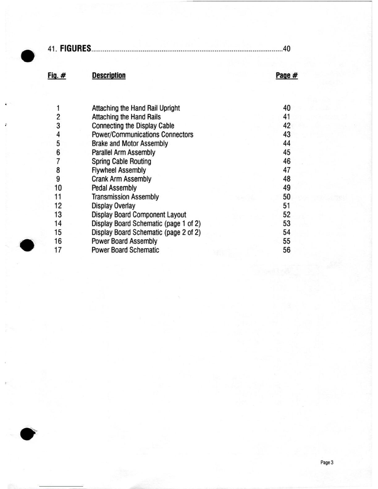
Attaching
The
Hand
Rail
Upright
2
/
11
~
Attaching
the
Hand
Rails
Attach
the
hand
rail
upright
(2)
to
the
chas-
sis
(1)
using
two
5/16"
screws
(6),
flat
wash-
ers
(7)
and
lock
washers
(8)
as'
shown
in
Fig.
1.
Make
sure
that
the
display
cable
goes
through
the
slot
and
the
display
is
facing
to-
ward
the
chassis.
Finger
tighten
screws,
wrench
tighten
after
hand
rails
are
installed.
Fig. 2
Fig. 1
Insert
the
clamps
(5
&
6)
into
the
upright
so
that
the
threaded
holes
are
facing
up
to
check
the
fit
and
to
see
how
they
insert,
then
re-
move
the
clamps
(you
may
need
a
soft
mal-
let
to
tap
the
clamps
in).
Slip
the
hand
rails
(3)
over
the
black
nylon
plugs
on
the
rear
foot.
Slip
the
right
(4)
and
left
(5)
clamps
over
the
hand
rails
so
that
the
threaded
holes
-~~~
face
up
when
pushed
into
the
upright
(2)
as
..
~-
shown
in
Fig.
3.
The
easiest
way
to
insert
the
clamps
(5
&
6)
into
the
upright
(2)
is
to
check
the
alignment
of
the
clamps
with
the
uprights.
It
may
be
necessary
to
twist
the
handrail
(4)
towards
the
display
then
pull
the
handrail
away
from
the
display
without
allowing
it
to
twist
to
get
the
proper
alignment.
If
this
is
difficult,
use
a1/2"
socket
and
loosen
the
5/16"
boh
that
holds
the
black
nylon
plug
underneath
the
rear
foot.
This
allows
easy
alignment
of
the
handrail.
Screw
in
the
1/4"
screws
(9)
with
the
flat
washers
(10)
but
do
not
tighten.
Move
the
up-
right
forward
or
backward
to
locate
the
hand
rails
1/2"
(inside)
from
the
edge
ofthe
clamp
(see
Fig.
2).
If
the
upright
will
not
move,
loosen
the
5/
16"
screws
at
the
base
of
the
up-
right.
Tighten
the
1/4"
screw
until
the
edge
of
the
clamp
is
flush
with
the
top
surface
of
the
upright.
Tighten
the
four
#1
0
screws
(11)
as
shown.
Now
the
5/16"
screws
atthe
base
of
the
upright
can
be
tightened
and
the
hand
rail
end
caps
(12)
can
be
inserted.
•
•
•
Page
5
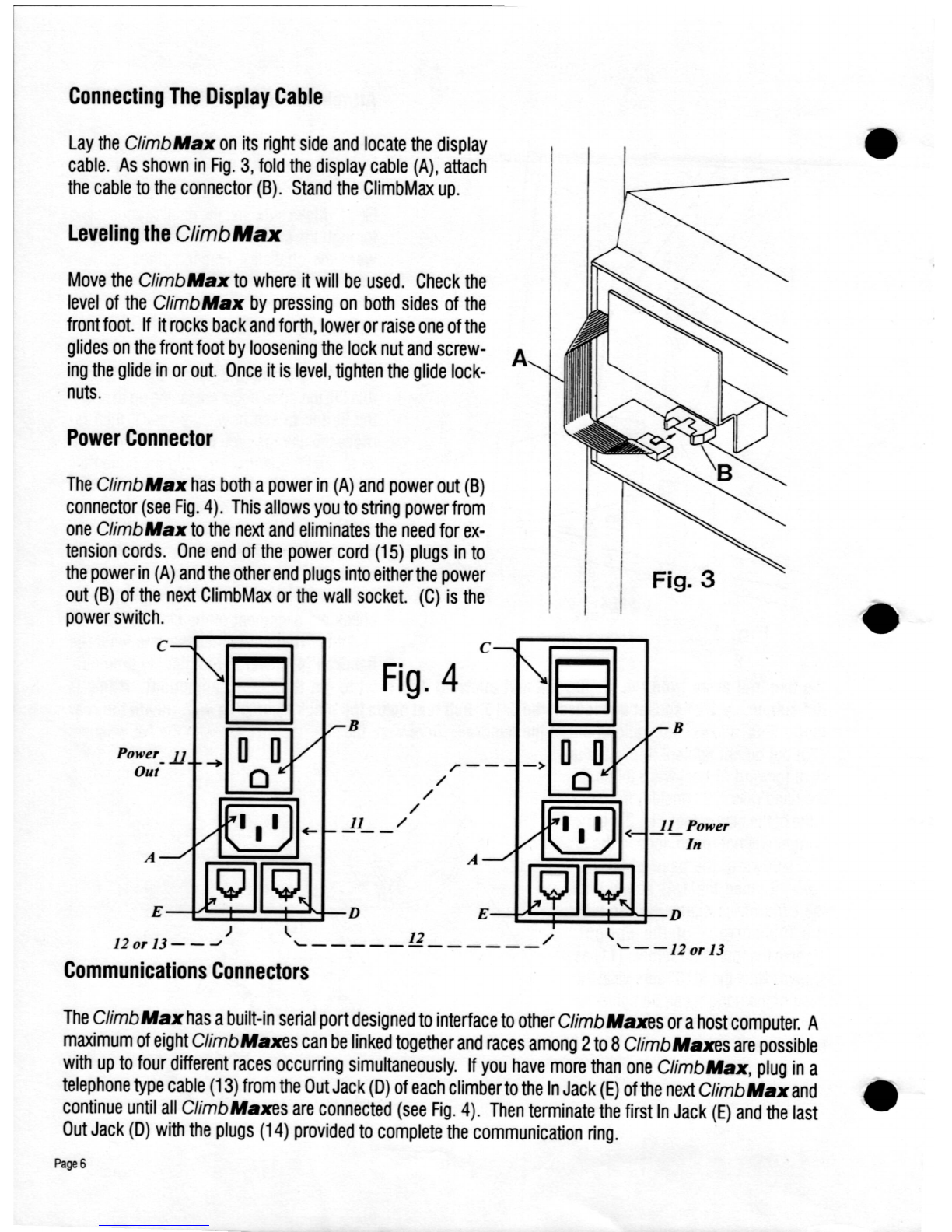
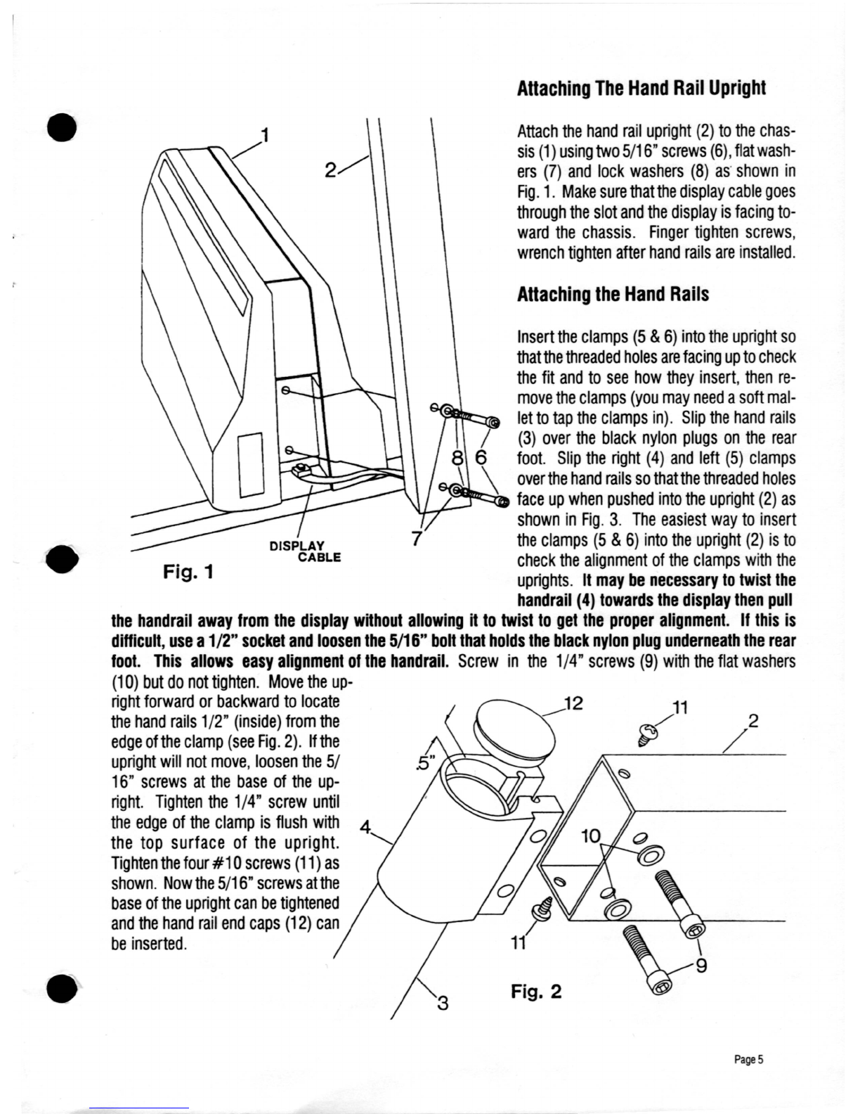
Connecting
The
Display
Cable
B
Fig. 3
<
~LPower
In
c
A
r--
/
/
/
/
Fig.
4
11
B
Power_lJ
Out
A
The
Climb
Max
has
both
a
power
in
(A)
and
power
out
(B)
connector
(see
Fig.
4).
This
allows
you
to
string
power
from
one
Climb
Max
to
the
next
and
eliminates
the
need
for
ex-
tension
cords.
One
end
of
the
power
cord
(15)
plugs
in
to
the
power
in
(A)
and
the
other
end
plugs
into
either
the
power
out
(B)
of
the
next
ClimbMax
or
the
wall
socket.
(C)
is
the
power
switch.
c
Move
the
ClimbMax
to
where
it
will
be
used.
Check
the
level
of
the
Climb
Max
by
pressing
on
both
sides
of
the
front
foot.
If
it
rocks
back
and
forth,
lower
or
raise
one
of
the
glides
on
the
front
foot
by
loosening
the
lock
nut
and
screw-
A
ing
the
glide
in
or
out.
Once
it
is
level,
tighten
the
glide
lock-
nuts.
Power
Connector
Leveling
the
ClimbMaJC
Lay
the
Climb
Max
on
its
right
side
and
locate
the
display
cable.
As
shown
in
Fig.
3,
fold
the
display
cable
(A),
attach
the
cable
to
the
connector
(B).
Stand
the
ClimbMax
up.
)
120r
13-
_-oJ
E
---1~:::t:::~:::t:::~-D
E---1~=i=~:±::t--D
~
12
/
~
'-------------
'---120r13
Communications
Connectors
The
Climb
Max
has
a
built-in
serial
port
designed
to
interface
to
other
ClimbMaxes
or
a
host
computer.
A
maximum
of
eight
ClimbMaxes
can
be
linked
together
and
races
among
2
to
8ClimbMaxes
are
possible
with
up
to
four
different
races
occurring
simultaneously.
If
you
have
more
than
one
ClimbMax,
plug
in
a
telephone
type
cable
(13)
from
the
Out
Jack
(D)
of
each
climber
to
the
In
Jack
(E)
of
the
next
Climb
Max
and
continue
until
all
ClimbMaxes
are
connected
(see
Fig.
4).
Then
terminate
the
first
In
Jack
(E)
and
the
last
Out
Jack
(D)
with
the
plugs
(14)
provided
to
complete
the
communication
ring.
Page
6
•
2.
SETUP
MODE
Setup
Mode
is
used
to
adjust
program
times,
to
select
various
options,
including
Prompted
or
Step
and
Go
operation,
and
to set
the
jackpot
count.
Enter
Setup
Mode
by
holding
the
DISPLAY
SHIFT
key
(Model
150
climbers
use
the
Shift
key)
while
turning
the
ClimbMaJC
on.
The
readouts
show
SETUP
MODE
and
the
Interval
display
shows
a
moving
pattern.
The
keys
have
special
functions
in
Setup
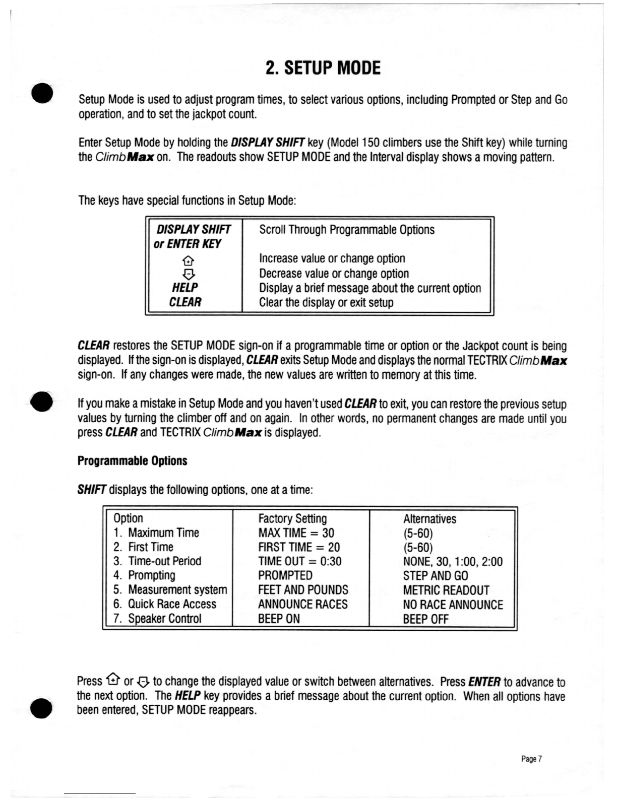
Mode:
DISPLAY
SHIFT
or
ENTER
KEY
G
o
HELP
CLEAR
Scroll
Through
Programmable
Options
Increase
value
or
change
option
Decrease
value
or
change
option
Display
a
brief
message
about
the
current
option
Clear
the
display
or
exit
setup
CLEAR
restores
the
SETUP
MODE
sign-on
if
a
programmable
time
or
option
or
the
Jackpot
count
is
being
displayed.
If
the
sign-on
is
displayed,
CLEAR
exits
Setup
Mode
and
displays
the
normal
TECTRIX
ClimbMaJC
sign-on.
If
any
changes
were
made,
the
new
values
are
written
to
memory
at
this
time.
•
If
you
make
a
mistake
in
Setup
Mode
and
you
haven't
used
CLEAR
to
exit,
you
can
restore
the
previous
setup
values
by
turning
the
climber
off
and
on
again.
In
other
words,
no
permanent
changes
are
made
until
you
press
CLEAR
and
TECTRIX
ClimbMaJC
is
displayed.
Programmable
Options
SHIFT
displays
the
following
options,
one
at
a
time:
Option
Factory
Setting
Alternatives
1.
Maximum
Time
MAX
TIME
=
30
(5-60)
2.
First
Time
FIRST
TIME
=
20
(5-60)
3.
Time-out
Period
TIME
OUT
=
0:30
NONE,
30,
1
:00,
2:00
4.
Prompting
PROMPTED
STEP
AND
GO
5.
Measurement
system
FEET
AND
POUNDS
METRIC
READOUT
6.
Quick
Race
Access
ANNOUNCE
RACES
NO
RACE
ANNOUNCE
7.
Speaker
Control
BEEP
ON
BEEP
OFF
•
Press
'0
or
0.
to
change
the
displayed
value
or
switch
between
alternatives.
Press
ENTER
to
advance
to
the
next
option.
The
HELP
key
provides
a
brief
message
about
the
current
option.
When
all
options
have
been
entered,
SETUP
MODE
reappears.
Page
7

PROGRAMMABLE
TIMES
1.
MAXTIME
The
length
of
the
longest
workout
can
be
adjusted
in
5-minute
increments
from
5
to
60.
2.
FIRST
TIME
The
number
of
minutes
first
offered
after
weight
has
been
entered
also
ranges
from
5
to
60.
It
can't
be
longer
than
the
maximum
time.
3.
TIME
OUT
The
length
of
time
that
the
climber
retains
its
settings
before
resetting
and
displaying
the
sign-on
message
if
the
user
quits
stepping.
The
period
can
be
set
to
thirty
seconds,
one
minute,
two
minutes,
or
NONE,
which
keeps
it
from
timing
out.
OPTIONS
4.
PROMPTING
Prompted
Prompting
begins
when
you
press
a
key
or
when
you
start
climbing.
5.
MEASUREMENT
SYSTEM
Feet
and
Pounds
Distance
is
displayed
in
feet
and
weight
is
entered
in
pounds.
6.
QUICK
RACE
ACCESS
Announce
Races
Idle
climbers
display
a
message
during
a
race
countdown,
and
anyone
can
join
by
just
pressing
ENTER.
7.
SPEAKER
CONTROL
Beep
On
The
speaker
operates.
Page
8
Step
and
Go
If
you
start
climbing
without
press-
ing
a
key,
the
climber
starts
in
Manual.
If
you
press
a
key
first,
prompting
begins.
Pressing
ENTER
in
Manual
always
begins
the
prompt-
in
sequence.
Metric
Readouts
Distance
is
displayed
in
meters
and
weight
is
entered
in
kilograms
No
Race
Announce
No
special
handling
for
races.
Beep
Off
Turns
the
speaker
off
completely.
•
•
•
3.
TEST
MODE
Test
Mode
is
used
to
test
the
climber's
electronic
hardware.
You
enter
Test
Mode
by
holding
the
ENTER
key
down
while
turning
the
ClimbMaJlon.
All
the
displays
light
up
as
long
as
you
hold
the
key
down.
When
you
release
the
key,
the
readouts
show
the
version
number
of
the
microprocessor
software
and
the
state
of
the
slack
switch
(SLACK
or
TIGHT).
The
Interval
and
speedometer
displays
show
moving
patterns.
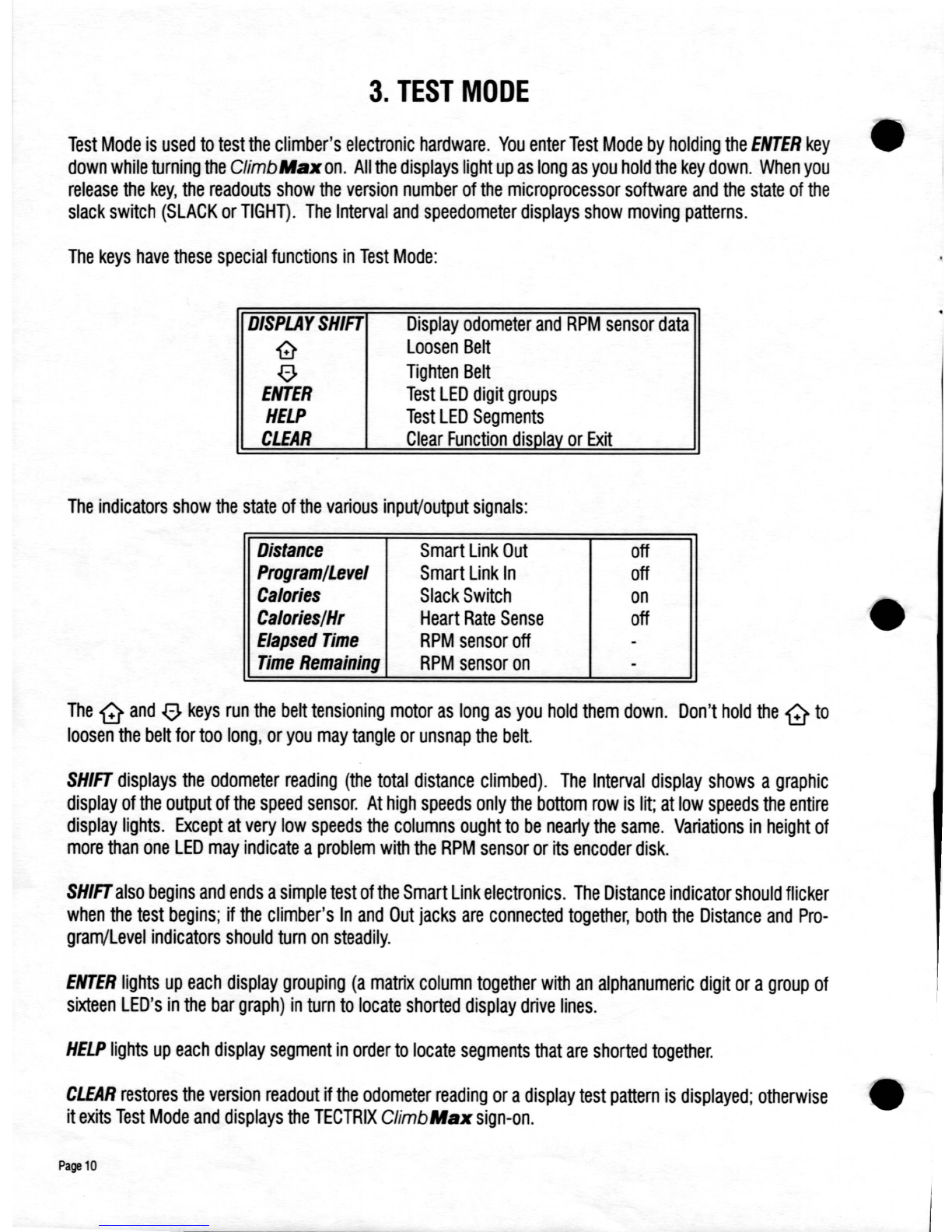
The
keys
have
these
special
functions
in
Test
Mode:
DISPLAY
SHIFT
'0
00
ENTER
HELP
CLEAR
Display
odometer
and
RPM
sensor
data
Loosen
Belt
Tighten
Belt
Test
LED
digit
groups
Test
LED
Segments
Clear
Function
disolav
or
Exit
The
indicators
show
the
state
of
the
various
inpuVoutput
signals:
Distance
Smart
Link
Out
off
Program/Level
Smart
Link
In
off
Calories
Slack
Switch
on
Calories/Hr
Heart
Rate
Sense
off
Elapsed
Time
RPM
sensor
off
-
Time
Remaining
RPM
sensor
on
-
The
G
and
00
keys
run
the
belt
tensioning
motor
as
long
as
you
hold
them
down.
Don't
hold
the
G
to
loosen
the
belt
for
too
long,
or
you
may
tangle
or
unsnap
the
belt.
SHIFT
displays
the
odometer
reading
(the
total
distance
climbed).
The
Interval
display
shows
a
graphic
display
of
the
output
of
the
speed
sensor.
At
high
speeds
only
the
bottom
row
is
lit;
at
low
speeds
the
entire
display
lights.
Except
at
very
low
speeds
the
columns
ought
to
be
nearly
the
same.
Variations
in
height
of
more
than
one
LED
may
indicate
a
problem
with
the
RPM
sensor
or
its
encoder
disk.
SHIFT
also
begins
and
ends
a
simple
test
of
the
Smart
Link
electronics.
The
Distance
indicator
should
flicker
when
the
test
begins;
if
the
climber's
In
and
Out
jacks
are
connected
together,
both
the
Distance
and
Pro-
gram/Level
indicators
should
turn
on
steadily.
ENTER
lights
up
each
display
grouping
(a
matrix
column
together
with
an
alphanumeric
digit
or
a
group
of
sixteen
LED's
in
the
bar
graph)
in
turn
to
locate
shorted
display
drive
lines.
HELP
lights
up
each
display
segment
in
order
to
locate
segments
that
are
shorted
together.
CLEAR
restores
the
version
readout
if
the
odometer
reading
or
a
display
test
pattern
is
displayed;
otherwise
it
exits
Test
Mode
and
displays
the
TECTRIX
ClimbMaJl
sign-on.
Page
10

MAINTENANCE
•
This
section
covers
maintenance
that
should
be
regularly
performed
to
minimize
wear
and
to
keep
the
Climb
Max
in
top
operating
order.
The
following
recommendations
are
for
heavy
institutional
use
(8
or
more
hours
daily,
20
thousand
feet
climbed)
and
can
be
scaled
down
accordingly.
Required
Maintenance
4.
5.
6.
7.
8.
Maintenance
Procedure
Cleaning
Drive
Cable
/
Clevis
Replacement
Pedal/Cable
Clevis
Lubrication
Clutch
Bearing
Lube,
Chain,
Crank
Arm
&
Parallel
Shaft
Lube
Friction
Belt
Replacement
/
Switch
Ends
Period
Daily
8-10
Months
Weekly
Yearly
3-6
Months
3
Months
Feet
Climbed
5
Million
7
Million
3
Million
2
Million
•
•
4.
Cleaning
Keeping
the
Climb
Max
clean
helps
to
prevent
rust
and
dirt
from
getting
into
the
moving
parts.
The
Climb
Max
should
be
wiped
down
at
least
once
a
day
and
club
members
should
be
encouraged
to
wipe
off
the
climber
after
they
use
it.
Most
household
cleaners
are
fine
to
use
on
the
ClimbMaxexceptforthose
that
have
abrasives.
Solvents
should
not
be
used
on
any
plastic
parts.
A
stiff
scrub
brush
works
well
for
cleaning
dirt
off
the
pedals.
Scratches
or
chips
in
the
paint
should
be
touched
up
to
prevent
rust.
5.
Drive
Cable
/
Clevis
Bearing
&
Bolt
Replacement
Drive
Cable
-
Fig.
9,
Part
#12
and
Fig.
7,
Part
#
2.
Clevis
Bearing
&
Bolt
-
Fig.
9,
Part
# 4
.
The
drive
cables
and
clevis
bearing
&
bolt
should
be
replaced
every
8
to
10
months
or
5
million
feet
climbed.
The
cables
wear
internally,
darkening
with
use.
A
black
cable
is
a
worn
cable
and
will
even-
tually
break
(see
section
34
for
replacement).
The
clevis
bearing
&
bolt
should
be
inspected
when
replacing
a
drive
cable.
A
corroded
bolt
will
quickly
wear
through
the
bearing.
This
will
result
in
damage
to
the
crank
arm
leading
to
an
expensive
repair
(see
section
37
for
replacement).
6.
Pedal/Cable
Clevis
Lubrication
Pedal
Parallel
Arm
Bearing
(see
Fig.
10,
Part
#4)
Cable
Clevis
Bearing
(see
Fig.
9,
Part
#4)
A
few
drops
of
light
machine
oil
(example:
'TRI-FLO'
or
3-in-1
oil)
each
week
will
improve
wear
life.
Make
sure
to
wipe
off
excess
oil
as
it
will
attract
dirt.
Inspect
the
clevis
action.
The
clevis
must
swivel
freely.
Page
11

7,
Clutch
Bearing,
Chain,
Crank
Arm
&
Parallel
Shafts
Lubrication
7,1
Clutch
Bearing
Lubrication
Remove
the
cover.
See
Fig,
11,
item
#7,
Apply
a
few
drops
of
90
weight
gear
oil
only,
in
the
hole,
CRANK
ARIi
ASSEIiBLY
Fi,ure 9
CIANI
All
ASSY.
::~~~
:=:1
,
--
-,.
I
CRAll:
MIl
-
LfFI
5«]1. 1
2
CRAll:
MIl
-
R(()lT
5«]15 1
]1',I-I..,..a112"
_De;
44021
4
•
],111".15132",112"
_De;
_ 2
(I/(}Wf
10
ALIQI
WIDI
IIITOI
I.
ORllIE
CAIl.E,
mil
U1IU1IC'
COIPO/fIltTS
,
--
-,
5
IlETADe;
RIll; -
;zs..,
4l106
6l'a1-],III"
uve
lPR. WASIQ 401l'
7
PMIT
lIW'T
51111l
8
l'a1I2"
•.
IO
lKl.
WASIQ
40031
9.48"
•.
lIr
lI'Il.lJj WASIQ
4n!9
10
],III"xlW
Q..EY(S
lIJIEl
5~16
II
5116'-18
NI'lII:
lIlT
Q]]]
12
DRive
CAIl.E
51015
13
CRAll:
...
I.IF8!
5Oal2
7.2
Chain
Lubrication
Remove
the
cover
(see
section
25),
Use
a
throwaway
rag
to
wipe
the
sludge
from
the
chain,
Apply
a
roller
chain
lubricant
(example:
CRC
brand
part
number
03050)
evenly
and
wipe
the
chain
to
remove
the
excess,
14
15
17
PEDAL
ASSEMBLY
-
61063
1
NIl.,.
Nlrl
I
PBlAl.
-
1IAOt.
,
AICIlIZED
52011
231. I
718
I
SIB
IlEAl!II(j
~
3
112
I
1!lI32
I
112
IlEAl!II(j
...cI2S
•
ltll
I
15132
I
112
IlEAl!II(j
"'4026
5
PEOAl
llJf'EI!
SllXl3
Page
12
<
......
.......
PEDAL
ASSEMBLY
Fiture
10
OTHER
UFERENCE
COIPONENTS
1
NIl.,.
Nlrl
6ltll-16
lEX
FUICiE
lIlT
.2043 I
731. I
1-5116
I.lBl
WASIO
OJ31 2
831.
WAVE
SI'l!II(j
WASIO
~
I
931. E;/11(j
.3201
I
10
SIB-18.Jo\1l
lIlT
.20~
I
II
SIB
SEIlI!A
TEll
un
WASIO
Ol2ll
1
12
RIGHT
CJ!N«
Al!Il
-
IIAOtIIEll
54015
I
13
ltll-18 I1-118 lIl.T .1043 I
I.
ltll
QJMD
SI'l!II(j
wASIEl!
~
I
IS
ltll
DIll
TE
IIIDlZE
wASIEl!
44027
I
16
PBlAl.
SHoIFT
5I
048
I
J7
PAI!ALla.
Al!Il
52021
I

•
•
•
PARALLEL
ARM
ASSEMBLY
Fi:ure 6
5
PARALLEL
ARI
ASSY.
-
61032
I
NIr
lUll
1111
I
trf.
I
PARAlLEl
ARM
5202\
2
2
314.
\51\6 •
314
lEAl/II(;
4400!1
2
OTHER
REFERENCE
CO.PONEIiTS
I,.,-
NIl
I
3
314.
1111
NYLl)l
W~
0)25
4
4
314
WAVE
WAS!£R
4lXXJ5
\
5PARAllR
ARM
SHAFT
5\172
\
6
314
E-I1II(;
43201
2
7.3
Crank
Arm
(see
Fig.
9)
&
Parallel
(see
Fig.
6)
Shafts
Lubrication
Apply
a
few
drops
of
light
machine
oil
(example:
'TRI-FLO'
or
3-in-1
oil)
on
the
pedal
bearing
surfaces.
Wipe
off
any
excess
so
that
it
does
not
attract
dirt.
At
the
base
of
each
crank
arm
is
a
lubrication
point.
Apply
three
squirts
of
a
polymer
grease
(example:
Clenesco
Polylube')
to
each
crank
arm
lubrication
point.
Apply
one
small
squirt
between
the
two
parallel
arms.
8.
Friction
Belt
Replacement
/
Switch
Ends
The
friction
belt
should
be
replaced
when
the
speed
control
degrades
(see
sections
21
&
22).
In
many
cases
the
belt
can
be
reversed
to
extend
its
life
because
the
major
wear
is
at
the
end
that
attaches
to
the
motor
pulley.
Inspect
the
flywheel
surface
and
remove
any
flywheel
deposits
with
Scotch
Brite
or
sandpa-
per.
9.
Pedal
Bearing
Inspection
Pedal/Parallel
Arm
Bearing
-
Fig.
10,
Part
#4
The
3/8"
bearings
should
be
checked
annually
or
after
7
million
feet
and
replaced
if
needed
(see
section
39).
Page
13

TROUBLESHOOTING
GUIDE
This
guide
will
help
to
locate
a
problem
in
the
ClimbAfax.
Troubleshooting
is
much
easier
with
spare
parts.
We
highly
recommend
the
purchase
of
a
Dealer
Service
Kit
as
this
guide
refers
to
spare
parts
in
some
sections.
DISPLAY
ERRORS
10.
CAN'T
SLOW
DOWN
or
CONTROL
LOST
11.
NO
SLACK
12.
NO
BRAKE
13.
MEMORY
LOST
14.
A
Numeral
Appears
in
the
Interval
Display
OTHER
PROBLEMS
15.
Some
LED's
(lights)
Are
Out
On
The
Display
And
There
Is
No
Beep
When
The
Power
Is
Turned
On
16.
All
LED's
(lights)
Are
Out
On
The
Display
And
There
Is
No
Beep
When
The
Power
Is
Turned
On
17.
Reset
Problem
18.
A
Key
On
The
Display
Console
Doesn't
Work
19.
Pedal
Squeak
20.
A
Pedal
Doesn't
Return
To
The
Top
or
A
Pedal
Won't
Go
Down
21.
Speed
Control
Is
Jerky
Or
Varies
Speed
22.
No
Speed
Control
And
No
Error
Message
Is
Displayed
23.
The
ClimbAfax
Won't
Accelerate
To
Top
Speed
24.
Cannot
Select
Group
Race
DISPLAY
ERRORS
The
first
thing
to
do
if
you
get
a
Display
Error
is
to
press
CLEAR.
Sometimes
the
errors
'CAN'T
SLOW
DOWN'
or
'CONTROL
LOST'
may
be
displayed
in
conjunction
with
other
errors
such
as
'NO
BRAKE'
or
'
NO
SLACK.'
If
this
is
the
case,
follow
the
'CAN'T
SLOW
DOWN'
or
'CONTROL
LOST'
error.
The
following
is
a
list
of
things
to
check
which
can
cause
'CAN'T
SLOW
DOWN'
or
'CONTROL
LOST':
10.
'CAN'T
SLOW
DOWN'
or
'CONTROL
LOST'
10.1
Friction
Belt
Disconnect
the
power
cord
from
the
Climb
Max
and
remove
the
cover
(see
section
25).
See
if
the
friction
belt
has
worn
through
or
is
disconnected.
If
this
has
happened
see
section
28,
Friction
Belt
Replacement.
Page
14
10.2
Electrical
Cables
•
If
the
belt
is
ok,
look
for
any
loose
connections
or
wires
around
the
power
board
or
motor
assemblies.
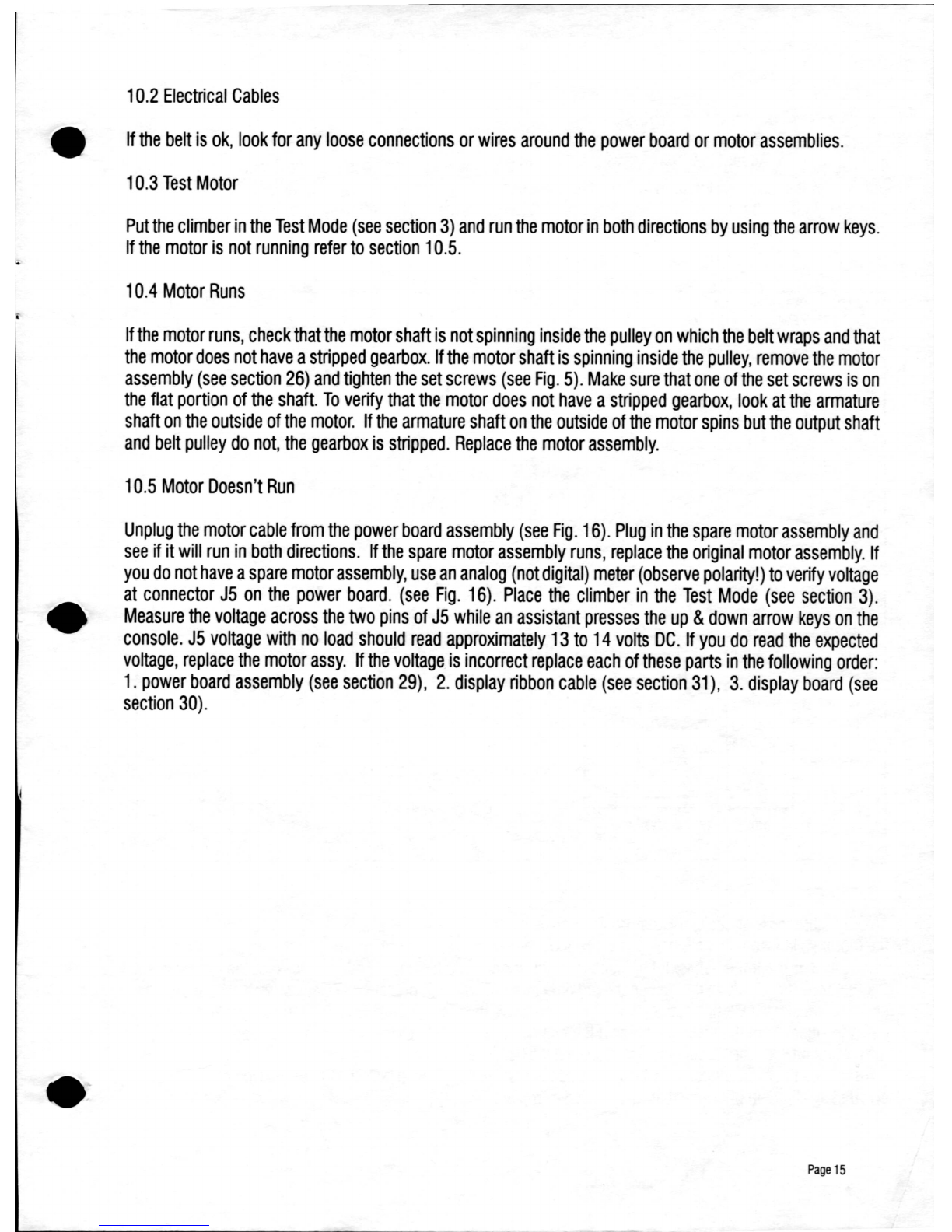
10.3
Test
Motor
Put
the
climber
in
the
Test
Mode
(see
section
3)
and
run
the
motor
in
both
directions
by
using
the
arrow
keys.
If
the
motor
is
not
running
refer
to
section
10.5.
10.4
Motor
Runs
If
the
motor
runs,
check
that
the
motor
shaft
is
not
spinning
inside
the
pulley
on
which
the
belt wraps
and
that
the
motor
does
not
have
a
stripped
gearbox.
If
the
motor
shaft
is
spinning
inside
the
pulley,
remove
the
motor
assembly
(see
section
26)
and
tighten
the
set
screws
(see
Fig.
5).
Make
sure
that
one
of
the
set
screws
is
on
the
flat
portion
of
the
shaft.
To
verify
that
the
motor
does
not
have
a
stripped
gearbox,
look
at
the
armature
shaft
on
the
outside
of
the
motor.
If
the
armature
shaft
on
the
outside
of
the
motor
spins
but
the
output
shaft
and
belt
pulley
do
not,
the
gearbox
is
stripped.
Replace
the
motor
assembly.
10.5
Motor
Doesn't
Run
•
•
Unplug
the
motor
cable
from
the
power
board
assembly
(see
Fig.
16).
Plug
in
the
spare
motor
assembly
and
see
if it
will
run
in
both
directions.
If
the
spare
motor
assembly
runs,
replace
the
original
motor
assembly.
If
you
do
not
have
a
spare
motor
assembly,
use
an
analog
(not
digital)
meter
(observe
polarity!)
to
verify
voltage
at
connector
J5
on
the
power
board.
(see
Fig.
16).
Place
the
climber
in
the
Test
Mode
(see
section
3)
.
Measure
the
voltage
across
the
two
pins
of
J5
while
an
assistant
presses
the
up
&
down
arrow
keys
on
the
console.
J5
voltage
with
no
load
should
read
approximately
13
to
14
volts
DC.
If
you
do
read
the
expected
voltage,
replace
the
motor
assy.
If
the
voltage
is
incorrect
replace
each
of
these
parts
in
the
following
order:
1.
power
board
assembly
(see
section
29),
2.
display
ribbon
cable
(see
section
31),
3.
display
board
(see
section
30)
.
Page
15

'NO
SLACK'
&
'NO
BRAKE'
ERRORS
'NO
SLACK'
&
'NO
BRAKE'
refers
to
the
slack
switch
located
on
the
motor
assembly
(see
Fig.
5).
The
purpose
of
the
slack
switch
is
to
tell
the
microprocessor
(located
on
the
display
board)
whether
the
belt
is
loose
or
tight
on
the
flywheel.
When
the
Climb
Max
is
turned
on
or
after
someone
stops
climbing
the
microprocessor
uses
the
slack
switch
to
initialize
the
belt
position.
The
following
is
the
initialization
process:
MOTOR
ASSEMBLY
-
61015
,,mlUl
,m,
I
GEAR
I()TlR
:JiOO5
2
I()T!R
II1ACKET
51021
3
SLACl:
SVJT(H
1ml
4
SLACl:
SVJT(H
AIlJJST
SlOT
-
5
I()TlR
LEADS
V/TlJ!llIO
14042
6
IB.T
Pll.LEY
(5116'
tnE)
46012
7IB.T
Pll.LEY
SCREV
STlfl
41lDi
8IB.T
OCHlR
511155
9IB.T
OCHlR
SCREV
STlfl
41lDi
'OTOR
ASSY.
-
FRONT
VI"
OTHER
REFERENCE
CO.PONENTS
,
NIr..
,lit
1
10
H1I(TJ~
IELl
610n
II
FL
YVtEEl
61005
12
DIS(
51018
13
IIPM
SENSlJ/
ASSY.
61
()4.4
14
SENSD1
INIllJT
AIlJJST
15
SENSD1
FI1lJH
18ACl:
AO.1JST
-
14
16
SlACl:
SVJT(H
ARM
1m7
17
SlACl:
SVJT(H
CAELE
61021
BRAKE
fil'"
5
The
microprocessor
checks
the
status
of
the
slack
switch.
If
the
belt
is
pressed
upon
the
slack
switch
arm,
the
motor
will
loosen
the
belt.
If
after
1.5
seconds
the
slack
switch
is
not
deactivated
the
display
will
show
a
'NO
SLACK'
error.
If
the
belt
is
not
pressed
upon
the
slack
switch
arm,
the
microprocessor
then
commands
the
motor
to
run
slowly
in
the
belt
tightening
direction
until
the
belt
presses
the
slack
switch
arm.
If
after
12
seconds
the
slack
switch
is
not
activated
the
display
will
show
a
'NO
BRAKE'
error.
Once
the
microprocessor
gets
the
signal
from
the
slack
switch
that
the
belt
has
pressed
it
(the
belt
is
tight),
the
microprocessor
runs
the
motor
fast
in
the
belt
loosening
direction
until
the
belt
is
off
the
slack
switch
(this
is
the
loose
point).
If
after
1.5
seconds
the
slack
switch
is
not
deactivated
the
display
will
show
a
'NO
SLACK'
error.
No
error
will
occur
if
you
start
climbing
prior
to
initialization
being
completed.
Page
16

11.
'NO
SLACK"
11.1
Test
Motor
•
Remove
the
cover
(see
section
25).
Put
the
climber
in
the
Test
Mode
(see
section
3)
and
run
the
motor
in
both
directions
by
using
the
arrow
keys.
If
the
motor
is
not
running
refer
to
section
10.5.
11.2
Test
Slack
Switch
Place
the
Climb
Max
in
Test
Mode
(see
section
3).
Watch
the
'CALORIES'
LED
on
the
display
board
while
pressing
the
slack
switch
on
the
motor
assembly.
The
'CALORIES'
LED
should
be
ON
when
the
slack
switch
is
NOT
pressed,
and
the
'CALORIES'
LED
should
go
OFF
when
the
slack
switch
is
pressed.
Pre-serial
number
166190
ClimbMaxes
(Model
150)
require
an
assistant
to
observe
the
'CALORIES'
LED
while
you
press
the
slack
switch.
Current
models
emit
an
audible
tone
in
response
to
the
slack
switch.
(A
status
indicator
also
displays
'SLACK'
or
'TIGHT'
on
the
readouts).
If
the
climber
passes
the
slack
switch
test,
but
displays
a
'NO
SLACK'
error,
the
slack
switch
may
be
out
of
adjustment.
Refer
to
section
27
for
slack
switch
adjustment
procedure.
11.3
Bad
Slack
Switch
If
the
'CALORIES'
LED
(or
audible
tone)
does
not
respond
to
the
slack
switch
as
described
above,
turn
the
climber
off.
Disconnect
the
slack
switch
cable
from
the
power
board
assembly
(see
Fig.
16).
Plug
the
slack
switch
cable
of
the
spare
motor
assembly
into
the
power
board
without
mounting
the
spare
motor
assembly
and
repeat
the
test.
If
the
climber
now
passes
the
slack
switch
test,
replace
the
slack
switch
and
slack
switch
cable.
Otherwise,
plug
the
original
slack
switch
back
in
and
replace
the
following
parts
in
this
order:
1.
display
ribbon
cable
(see
section
31)
2.
power
board
assembly
(see
section
29),
3.
display
board
(see
section
30).
•
12.
'NO
BRAKE'
12.1
Belt
Remove
the
cover
(see
section
25).
See
if
the
friction
belt
has
worn
through
or
is
disconnected.
If
this
has
happened
see
section
28,
Friction
Belt
Replacement.
12.2
Test
Motor
Put
the
climber
in
the
Test
Mode
(see
section
3)
and
run
the
motor
in
both
directions
by
using
the
arrow
keys.
If
the
motor
is
not
running
refer
to
section
10.5.
12.3
Test
Slack
Switch
Test
the
slack
switch
as
described
in
section
11.2.
If
the
climber
passes
the
slack
switch
test,
but
displays
a
'NO
BRAKE'
error,
the
slack
switch
may
be
out
of
adjustment.
Refer
to
section
27
for
slack
switch
adjustment
procedure.
12.4
Slack
Belt
Test
•
If
the
motor
is
running
and
the
slack
switch
is
adjusted
properly
(see
section
11.2)
turn
the
Climb
Max
off
and
on.
Start
climbing
to
100
fVmin
and
stop.
Watch
the
belt
as
the
flywheel
slows.
If
the
motor
assembly
unwinds
an
exces-
sive
amount
of
belt,
check
for
friction
belt
wear
and
belt
residue
on
the
flywheel
surface.
If
there
is
considerable
wear
and
residue,
replace
or
flip
the
belt
end
for
end
and
use
Scotch
Brite
or
sandpaper
to
remove
the
residue.
If
the
motor
passes
the
motor
test
(see
section
10.4
and
12.2)
and
all
prior
tests
have
been
completed
but
the
motor
still
gives
a
poor
response
in
operation,
replace
the
motor
assembly.
Page
17
,-----------------
- -
--------
13.
'MEMORY
LOST'
13.1
The
contents
of
the
permanent
memory
have
been
lost.
If
this
occurs,
Setup
mode
is
automatically
selected.
The
Odometer
and
Use
Count
are
set to
zero,
the
user/club
program
is
cleared,
and
program
time
defaults
to
twenty
minutes.
13.2
The
permanent
memory
in
the
Climb
Max
should
be
able
to
retain
its
contents
for
at
least
ten
years.
If
this
error
consistently
occurs
before
that
time,
you
may
consider
replacement
of
the
display
board.
14.
A
Numeral
Appears
in
the
Interval
Display
14.1
This
indicates
a
problem
with
the
display
electronics.
Sometimes
it
can
be
generated
by
turning
the
climber
off
and
on
too
quickly;
it
may
also
occur
in
response
to
an
irregularity
in
the
electrical
power
(such
as
a
surge
or
a
brownout).
This
can
be
considered
normal,
and
the
display
can
be
reset
by
slowly
turning
the
power
off
then
on
again.
Use
your
spare
motor
assembly
to
test
the
climber.
The
motor
assembly
may
be
using
too
much
power.
If
you
do
not
have
a
spare
motor
assembly,
put
the
climber
in
Test
Mode
(see
section
3).
Press
and
hold
the
down
arrow
key.
Keep
pressing
the
down
arrow
key
even
after
the
motor
assembly
has
tightened
the
belt
as
far
as
possible.
If
the
display
resets
(all
LEOs
go
off
then
on)
at
this
time,
the
motor
assembly
may
be
causing
the
problem
and
should
be
replaced.
If
the
motor
assembly
does
not
resolve
the
problem
and
the
number
persists
or
if it
appears
while
the
Climb
Max
is
in
operation,
the
display
board
may
need
replacement
(see
section
30).
If
replacement
of
the
display
board
does
not
resolve
the
problem,
replace
and
test
the
following
parts
in
this
order:
1.
power
board
assembly
(see
section
29)
2.
display
ribbon
cable
(see
section
31)
3.
display
board
(see
section
30)
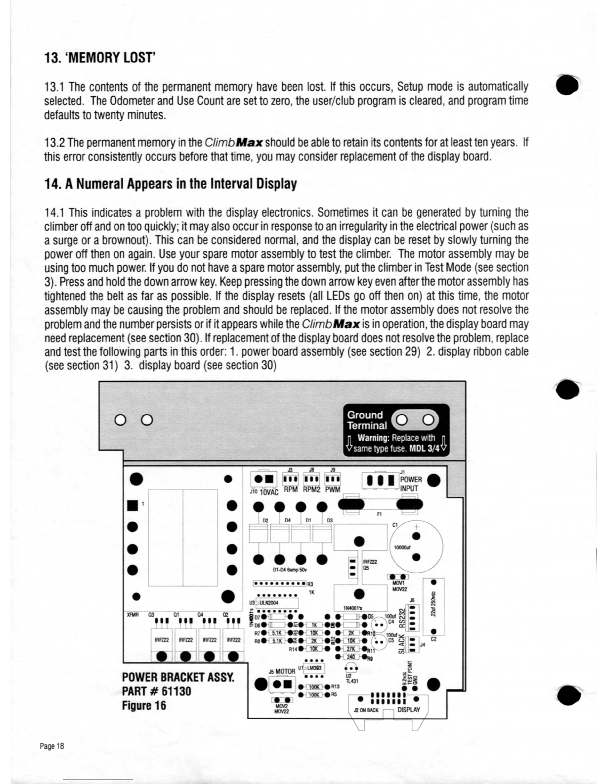
POWER
BRACKET
ASSY.
PART
#
61130
Figure
16
Page
18
o0
•
•
•
•
•
• I
Le:-J
II'
.:.,
~
,-----,
J1
0
10VAC
RPM
RPM2
PWM
J5
MOTOR
u
Uotl83
.Le:-J.····
R13
e-ru!~R5
•
•
•
•
1_
OTHER
PROBLEMS
15.
Some
LED's
(lights)
Are
Out
On
The
Display
And
There
Is
A
Beep
When
The
Power
Is
Turned
On
Power
up
in
the
Test
Mode
(see
section
3)
to
check
for
LED's
out.
Replace
the
display
board
(see
section
30)
if
there
are
some
LED's
out.
16.
All
LED's
(lights)
Are
Out
On
The
Display
And
There
Is
No
Beep
When
The
Power
Is
Turned
On
16.1
Blown
Fuse
Remove
the
cover
(see
section
25)
and
check
the
fuse
(11
OVAC
-
MOL
3/4A
250V,
or
220V
-
MOL
1/2A
250V)
located
on
the
power
board
(see
Fig.
16).
Check
the
fuse
for
zero
ohms
(good)
using
a
volt
ohm
meter
(a
visual
check
is
not
reliable).
Usually
a
fuse
doesn't
blow
for
no
reason
so
it
may
blow
again
(because
it
is
a
slow
blow
fuse
it
may
take
up
to
a
minute
to
blow).
If
it
does,
replace
the
fuse
and
unplug
all
of
the
connectors
except
J1
(see
Fig.
16).
If
it
blows
again,
replace
the
power
board
assembly.
If
it
doesn't
blow,
plug
each
connector
back
in
one
at
a
time
to
find
the
part
that
is
causing
the
fuse
to
blow.
Replace
that
part.
16.2
Power
Switch
Test
Check
that
all
wires
are
intact
on
the
switch
plate
and
power
board.
Using
the
volt
ohm
meter,
check
that
the
power
switch
is
supplying
110
volts
AC
to
the
power
board.
Place
the
meter
probes
on
the
black
and
white
wires
on
top
of
the
power
switch
(switch
on
and
power
cord
plugged
in).
CAUTION:
Care
is
required
when
reading
high
voltage.
Do
not
touch
the
two
leads
of
the
volt
ohm
meter
together
during
the
test
as
this
can
create
a
short.
If
no
AC
voltage
is
present
at
the
power
switch
try
a
different
power
cord.
Make
sure
that
110
VAC
is
present
at
the
wall
outlet.
If
there
is
still
no
power,
replace
the
switch
plate
assembly
(see
section
33).
16.3
Power
Board
Test
(see
Fig.
16
&
17)
Check
that
there
is
9.2
+/-.2
volts
DC
at
the
test
points
(labeled
'9.2
VDC'
and
'GND')
located
in
the
right
bottom
corner
of
the
board
(older
versions
of
the
power
board
do
not
have
the
test
points,
voltage
may
be
tested
at
pin
14
on
the
display
connector
(J2)
using
pin
1
(or
the
square
pad)
as
the
ground
reference).
Ifthe
voltage
reading
is
less
than
9
volts,
unplug
the
display
ribbon
cable
at
the
power
board
(J2)
and
read
the
voltage
again.
If
it
is
still
less
than
9
volts,
replace
the
power
board
assembly.
If
the
voltage
is
correct,
replace
and
test
each
of
these
parts
in
the
following
order:
1.
display
ribbon
cable
(see
section
31),
2.
display
board
(see
section
30).
Page
19

17.
Reset
Problem
If
the
display
doesn't
light
when
you
first
switch
power
on,
try
switching
power
off
and
on
slowly
several
times.
The
microprocessor
(located
on
the
display
board)
may
have
had
a
bad
reset
and
hung
up.
A
bad
motor
assembly
may
cause
apparent
display
symptoms.
Examples
include:
1
Intermittent
reset
2.
Oscillating
reset
3.
Temporarily
display
LED's
(lights)
go
out
Such
motors
may
pass
the
motor
power
test
and
provide
acceptable
speed
regulation.
Use
your
spare
motor
assembly
to
test
the
climber.
If
you
do
not
have
a
spare
motor
assembly,
put
the
climber
in
Test
Mode
(see
section
3).
Press
and
hold
the
down
arrow
key.
Keep
pressing
the
down
arrow
key
even
after
the
motor
assembly
has
tightened
the
belt
as
far
as
possible.
If
the
display
resets
(all
LEOs
go
off
and
the
sign-on
prompt
is
displayed)
at
this
time,
the
motor
assembly
may
be
causing
the
problem
and
should
be
replaced.
Even
though
the
motor
assembly
passes
this
test,
it
could
be
the
source
of
the
problem
and
should
be
replaced.
If
the
motor
assembly
does
not
resolve
the
problem
replace
and
test
the
following
parts
in
this
order:
1.
power
board
assembly
(see
section
29)
2.
display
ribbon
cable
(see
section
31)
3.
display
board
(see
section
30)
Irvine,
CaIIfomIa
(BOO)
767-8082
Made
In
U.S.A.
CAUTIO.:
Stop
climbing
If
you
don't
feel
well!
•
Adjust
TIME
&
Enter
•
Select
PROGRAM
&
Enter
•
Adjust
LEVEL
&
Enter
."
..
J
...
,.
,
••
,
,.
Page
20
Table of contents
Other Tectrix Fitness Equipment manuals


