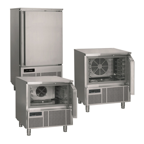
Tefcold BLC3 User manual

BLAST CHILLER/FREEZER
User Manual
EN
FR
IT
ES
PT
3
13
25
37
49

CONTENTS
1.
2.
3.
Important safety instructions .................................................................................. 4
Unpacking and installation ..................................................................................... 4
Electrical connection .............................................................................................. 5
Start-up of the cabinet ........................................................................................... 5
Capacity ................................................................................................................. 5
Recommendations for use ..................................................................................... 5
Blast chilling cycle ................................................................................................. 6
Shock freezing cycle .............................................................................................. 6
Cleaning and maintenance .................................................................................... 6
Service ................................................................................................................... 7
Disposal ................................................................................................................. 7
Technical manuals ............................................................................................... 61
Daily quick guide ................................................................................................. 10
General information
Thermostat XB570L / XB590L
Quick guide
3

IMPORTANT SAFETY INSTRUCTIONS
Important !
1. To obtain full use of the cabinet, we recommend reading this instruction manual.
2. It is the user’s responsibility to operate the appliance in accordance with the instructions given.
3. Contact your dealer immediately in case of any malfunctions.
4. Place the cabinet in a dry and ventilated place.
5. Keep the cabinet away from strongly heat-emitting sources and do not expose it to direct sunlight.
6. Always keep in mind that all electrical devices are sources of potential danger.
7. Do not store inammable material such as thinner, gasoline etc. in the cabinet.
8. We declare that no asbestos nor any CFC are used in the construction.
9. The oil in the compressor does not contain PCB
1. Do not block the ventilation holes.
2. Make sure that there is at least 15 cm. free space between the cabinet and the wall.
4
UNPACKING AND INSTALLATION
Remove the wooden pallet and the packing. External surfaces are supplied with a protection foil,
which must be removed before installation.
To ensure correct function it is important that the cabinet is level. If the cabinet is supplied with legs,
these can be adjusted.

ELECTRICAL CONNECTION
Important !
BLC3, BLC5 and BLC10 cabinets operates on 230 V/50 Hz.
BLC14 operates on 3x400 V/50 Hz.
Make sure that the cabinet is connected to a separate electrical group to avoid overload.
The wall socket should be easily accessible.
All earthing requirements stipulated by the local electricity authorities must be observed. The cabinet
plug and wall socket should then give correct earthing. If in doubt, contact your local supplier or
authorized electrician.
The main electrical connections must be done by skilled electricians.
If the cabinet has been horizontally placed during transport, please wait 2 hours before starting up
the cabinet.
5
START-UP OF THE CABINET
Before use, we recommend that the cabinet is cleaned, see the section on maintenance and
cleaning.
CAPACITY
BLC3 BLAST CHILLER/FREEZER
Model suitable to contain 3 trays with blast chilling capacity of 12kg and 8 kg in shock freezing.
BLC5 BLAST CHILLER/FREEZER
Model suitable to contain 5 trays with blast chilling capacity of 18kg and 14kg in shock freezing.
BLC10 BLAST CHILLER/FREEZER
Model suitable to contain 10 trays with blast chilling capacity of 40kg and 28 kg in shock freezing.
BLC14 BLAST CHILLER/FREEZER
Model suitable to contain 14 trays with blast chilling capacity of 55kg and 38kg in shock freezing.

RECOMMENDATIONS FOR USE
If the appliance remains inactive for a long period, proceed as follows
1. Use the automatic isolating switch to deactivate connection to the main electrical line.
2. Clean the appliance and surrounding areas thoroughly.
3. Spread a thin layer of cooking oil onto the stainless steel surfaces
4. Carry out all maintenance operations
5. Leave the door ajar to prevent the formation of mould and / or unpleasant odour.
Do not insert foodstus that are above the temperature of 90 °C.
Do not stack the materials to be preserved in contact with the internal walls so blocking the circulation
of air.
There must be a sucient space between the trays used in order to guarantee a sucient ow of
cold air on the entire product.
Never obstruct the inlet of the evaporator fans.
Products that are more dicult to chill because of their size should be placed in the centre.
Limit the number of times and the duration of time the door are opened.
After blast chilling/shock freezing the product, it can be stored in a preservation cabinet after having
been duly protected .A tag should be applied describing the contents of the product, blast chilling/
shock freezing date and expiry date. When the product has been blast chilled it must be preserved at
a constant temperature of +2 °C while if it has been shock frozen it must be preserved at a constant
temperature of -20 °C.
The chiller should be used for storage for short periods only.
To prevent bacterial contamination or contamination of any other biological
nature, the needle probe must be disinfected after use.
6

BLAST CHILLING CYCLE
7
With this operating modality the chiller keeps the temperature of the refrigerating compartment close
to zero during the entire chilling process in order to ensure a gradual drop in the temperature of the
product to +3 °C.In this way, ice crystals do not form on the surface of the product .This blast chilling
method should be used preferably for products that are not packed and whose physical/organoleptic
characteristics could be damaged by the formation of supercial ice (e.g. sh)
SHOCK FREEZING CYCLE
With this blast chilling modality the blast chiller maintains the temperature at a negative value below
-18 °C which is the end temperature of shock freezing .For shock freezing to be successful and fast,
food should be in small pieces, especially if it has a high fat content. The largest pieces should be
placed in central trays .If it takes longer than standard time to shock freeze and the sizes cannot
be reduced, decrease the quantity and precool the chiller compartment by starting an empty shock
freezing cycle before shock freezing the product.
CLEANING AND MAINTENANCE
Switch o the electrical connection at the socket.
The cabinet must be periodically cleaned. Clean the external and internal surfaces of the cabinet with
a light soap solution and subsequently wipe dry. External surfaces can be maintained using steel oil.
Do not spray the appliance with direct jets of water or using high pressure appliances.
Do not use iron wool. brushes or scrapers to clean the stainless steel as ferrous particles could be
deposited which ,on oxidizing, could lead to rust.
To remove hardened residues, use wooden or plastic spatulas or abrasive rubber pads.
Clean the condenser
Clean the condenser periodically.
As the ns of the condenser are very sharp, always wear protective gloves for the next phases.
Use protective masks and glasses in the presence of dust.
Whenever the condenser has a deposit of dust in correspondence with the ns, this can be
removed using a suction device or with a brush applied, using a vertical movement along the
direction of the ns.
No other instruments must be used, which may deform the ns and therefore the eciency of the
appliance.
To clean, proceed as follows:
1. Open the door (A) of the appliances.
2. Remove the lower panel(B) from the technical compartment: to do this, remove the screw
fasteners(C)
3. It is now possible to clean the nned part of the condenser (D) using suitable tools and
protection devices.
4. After cleaning, close the control panel and x it with the screws removed beforehand.
SERVICE
The cooling system is a hermetically sealed system and does not require supervision, only cleaning.
If the cabinet fails to cool, check if the reason is a power cut.
If you cannot locate the reason to the failure of the cabinet, please contact your supplier. Please
inform model and serial number of the cabinet. You can nd this information on the rating label which
is placed inside the cabinet in the top right hand side.
DISPOSAL
Disposal of the cabinet must take place in an environmentally correct way. Please note existing
regulation on disposal. There may be special requirements and conditions which must be observed.
8

9
QUICK GUIDE
For the daily use

10
HOW TO SELECT A CYCLE
Push the to move among the cycles CY1 , CY2 , CY3 , CY4 and the holding
cycle .
The 5 programs have the default values shown in the diagrams next page.
CY1: Fast chilling and conservation. (Hard + soft chilling and holding)
CY2: Chilling and fast freezing. (Hard + soft chilling, freezing and holding)
CY3: Fast freezing. (Fast freezing and holding)
CY4: Fast freezing with alarm and stop. (Only fast freezing)
H: Hold mode function. (Hard chill or freezing)
dEF: For starting a manual defrost.
1.
2.
3.
4.
5.
6.
How to display the holding SET point.
While the Holding cycle is running (H-icon
lighted), push the key.
The Holding set point is displayed on the
upper display and the SETH labels is
displayed on the bottom display.
How to modify the holding SET point.
While the SETH is displayed, hold the
key pressed until the SETH label starts
ashing.
Use the arrow keys to modify the value and
press the key to conrm.
To conrm and exit, push the key again.
How to start a cycle.
Push the key and the selected cycle starts.
The yellow display is switched on.
Compressor is delayed by 3 min.
How to pause a cycle.
Push the key and the compressor and fan
will stop.
Stb will ash in the display during the pause.
Push the key to restart the cycle from the
point of interruption.
In any case the cycle automatically restarts
after the PAU time. (See manual)
How to stop a cycle.
Hold the key pressed untill the yellow
display switch o and the cycle is stopped.

11
CY1: Hard chill + soft chill + holding CY3: Freezing cycle + holding
CY2: Hard chill + soft chill + freezing + holding CY4: Freezing cycle then stop
H: Holding mode

© TEFCOLD A/S 2017
rfj_170218
Blast Chillers
+70 °C to +3 °C
The blast chilling cycle reduce the product temperature from
+70 °C to +3 °C in 90 minuttes.
Bacterial generation is accelerating in the gap between +60 °C
and +10 °C, therefore it is essential to cool the product as fast
as possible.
Furthermore vitamins, taste and odour are preserved.
Should then be stored in normally chiller at +2 °C.
Bacterials in general
Bacterials destroyed
Bacterial acceleration
Bacterial reduction/stop
Chill Freeze
Blast Freezers
+70 °C to -18 °C
The blast freezing cycle reduce the product temperature from
+70 °C to -18 °C in 240 minuttes.
The fast reduction of the product temperature increases the
lifetime of the product.
Furthermore the quality is preserved without major loss of
weight, liquid and taste.
Should then be stored in normally freezer at -20 °C.

1592006207 XB570L GB r1.1 26.08.2015
XB570L
2 /20
XB590L(XB570L)

1592006207 XB570L GB r1.1 26.08.2015
XB570L
3 /20
CONTENTS
1. PLEASE READ BEFORE USING THIS MANUAL........................................................................................2
2. SAFETY PRECAUTIONS..............................................................................................................................2
3. GENERAL FEATURES .................................................................................................................................2
4. MOUNTING & INSTALLATION.....................................................................................................................3
5. ELECTRICAL CONNECTIONS.....................................................................................................................3
6. CONNECTIONS ............................................................................................................................................3
7. FRONTAL PANEL .........................................................................................................................................3
8. QUICK START...............................................................................................................................................4
9. HOW TO SELECT A CYCLE.........................................................................................................................8
10. PARAMETERS ..............................................................................................................................................9
11. HOW A CYCLE IS DONE........................................................................................................................... 12
12. INSTALLATION AND MOUNTING............................................................................................................. 14
13. XB07PR - PRINTER (OPTIONAL)............................................................................................................. 15
14. ELECTRICAL CONNECTIONS.................................................................................................................. 16
15. TTL SERIAL LINE....................................................................................................................................... 17
16. USE OF THE PROGRAMMING “HOT KEY “............................................................................................. 17
17. ALARM SIGNALS....................................................................................................................................... 17
18. TECHNICAL DATA..................................................................................................................................... 18
19. STANDARD VALUE OF THE CYCLES. .................................................................................................... 18
20. STANDARD VALUES OF THE PARAMETERS. ....................................................................................... 19
1. PLEASE READ BEFORE USING THISMANUAL
•
This manual is part of the product and should be kept near the instrument for easy and quick reference.
•
The instrument shall not be used for purposes different from those described hereunder. It cannot be
used as a safety device.
•
Check the application limits before proceeding.
•
Dixell Srl reserves the right to change the composition of its products, even without notice, ensuring the
same and unchanged functionality.
2. SAFETY PRECAUTIONS
•
Check the supply voltage is correct before connecting the instrument.
•
Do not expose to water or moisture: use the controller only within the operating limits avoiding sudden
temperature changes with high atmospheric humidity to prevent formation ofcondensation
•
Warning: disconnect all electrical connections before any kind of maintenance.
•
Fit the probe where it is not accessible by the End User. The instrument must not beopened.
•
In case of failure or faulty operation send the instrument back to the distributor or to “Dixell S.r.l.” (see
address) with a detailed description of the fault.
•
Consider the maximum current which can be applied to each relay (see Technical Data).
•
Ensure that the wires for probes, loads and the power supply are separated and far enough from each
other, without crossing or intertwining.
•
In case of applications in industrial environments, the use of mains filters (our mod. FT1) in parallel with
inductive loads could be useful.
3. GENERAL FEATURES
The series XB has been created for fast chilling or freezing goods according to international food safety
standards.
There are FOUR types of cycles:
•
The CYCLES: Cy1, Cy2, Cy3, Cy4 are pre-set according to the most common cycles used in food -
safety applications; the user can select one of them according to his own requirements and modify it as
he wants.
•
Any cycle can be manually terminated before the normal.
•
Any cycle can use the insert probes (up to 3), they measures the internal temperature of the product.
•
During the Cycle there are no defrosts and the fans are always on, a defrost cycle can be done before
any freezing cycle.
•
The cycle is divided up to 3 phases completely configurable by theuser.

1592006207 XB570L GB r1.1 26.08.2015
XB570L
4 /20
•
Each instrument is provided with an output for remote display XR REP, which shows the temperature of
cabinets or goods.
•
The XB570L controller is provided with internal real time clock and can be connected to the XB07PR
printer. This means that a report, which includes all the main features of cycle, can be printed: start and
end of the cycle, length of the cycle, logging of the temperature of the cabinet and goods.
4. MOUNTING & INSTALLATION
Model XB570L is a controller for panel mounting: the cut out dimensions are 150x31 mm and it has to be
fixed with screws. The ambient operating temperature range is from 0.0 to 60°C. Avoid locations subject to
heavy vibration, corrosive gases or excessive dirt. The same warnings have to be applied to the probes.
Ensure enought ventilation around the instrument.
5. ELECTRICAL CONNECTIONS
The instruments are provided with a screw terminal block to connect cables with a cross section up to
2.5mm2 for probes and digital input.
Spade on 6.3 mm heat-resistant wiring for supply and loads. Before connecting cables make sure the power
supply complies with the instrument’s requirements. Separate the input connection cables from the power
supply cables, from the outputs and the power connections. Do not exceed the maximum current allowed
on each relay, in case of heavier loads, a suitable external relay has to be used.
The probes shall be mounted with the bulb upwards to prevent damages due to casual liquid infiltration. It is
recommended to place the thermostat probe away from air streams to correctly measure the average room
temperature. Place the defrost termination probe among the evaporator fins in the coldest place, where most
ice is formed, far from heaters and from the warmest place during defrost, to prevent premature defrost
termination.
6. CONNECTIONS
oA2 oA1
oA3
7. FRONTAL PANEL
5.1 PROBES CONNECTION
Door
Common
Conf.
Inp.
Def
Room
Insert
1
HOT
KEY
1
2
3
4
5
6
7
8
16A 8A 8A 8A 16A
250V~ 250V~ 250V~ 250V~ 250V~
20A 250V
16FLA(96LRA)
MAX
20A
25 26 27 28 29 30 31
9 10
Def
Light
11 12 13 14
N Line
Supply
Comp 115V~
17 18 19 20 21 Remote
Display
PRINTER
Alarm
Fan
RS485
Insert
3
Insert
2

1592006207 XB570L GB r1.1 26.08.2015
XB570L
5 /20
8. QUICK START
The upper display shows the temperature of the room probe.
The lower display shows the temperature of the inserts probe or the count down timer. To pass to the one
insert probe to the another one use the DOWN key.
DISPLAY
Temperature.
Timer or insert probe
Alarm and status icons.
If an icon or LED is on, the correspondent
function is enabled.
If an icon or LED is flashing, the
correspondent function is delayed.
8.2 KEYBOARD IN STAND-BY
HOW TO SELECT A CYCLE:
Push and release the
(3) key till the
desired cycle is selected.
HOW TO START A CYCLE: Push and
release the START/STOP button
(2). Il The correspondent yellow LED is
switched on..
HOW TO TEMPORARILY STOP THE
RUNNING CYCLE.
1.
Press and release the key.
2.
The compressor and the fan will be
stopped for the PAU time (see
parameters list) and the flashing
message “Stb” will be displayed.
3.
To restart the cycle press and release
the
key, the cycle will restart
from the some point at which it was
interrupted.
4.
In any case the cycle automatically
restarts after the PAU time.
HOW TO STOP A CYCLE
: hold pushed
the START/STOP
button (2) till the
yellow LED will be switched off.
8.1 DISPLAY

1592006207 XB570L GB r1.1 26.08.2015
XB570L
6 /20
HOW TO SET THE TIME (RTC)
Hold pushed the DOWN key (5) till the
Min label is displayed.
Use the UP and DOWN KEY to browse
the parameters.
-
TO MODIFY: push the
SET
button and then the UP
and
DOWN keys.
-
TO CONFIRM: push the SET
button.
TO EXIT THE RTC MENU: push both
SET+UP keys or wait for 5 sec.
UP key: browse the
menu:
-
Min= minutes
-
Hou= hours
-
daY= day
-
Mon= month
-
YEA= year
-
tiM= US/EUROPE time
HOW DISPLAY / MODIFY THE SET
POINT OF THE HOLDING PHASE
-
TO DISPLAY:
push and
release the SET
key (6), the
holding set point of the
selected cycle is displayed for
5 sec.
-
TO MODIFY:
while the set
point is displayed hol
d pushed
the SET key till the HdS label
start flashing. Use the UP and
DOWN key to modifiy the
value..
TO CONFIRM: push the SET key to
confirm the value and exit.
In this example the
holding set point of the
cycle 1 is modified.
In this example
the set point of
the holding
cycle is
modified.
HOW MODIFY A CYCLE:
1.
Push the
key (6) for several
seconds till the first parameter (CyS)
is displayed.
2.
Use the UP and DOWN keys to
browse the parameters.
3.
To modify a par
ameter push the SET
key and use the arrowkeys.
4.
Confirm the new value by pushing the
SET key.
5.
The new value is recorded even if the
programming is exited by time out.

1592006207 XB570L GB r1.1 26.08.2015
XB570L
7 /20
8.3 KEYBOARD WHEN A CYCLE 1,2,3,4 IS RUNNING
DISPLAY TEMPERATURES:
The upper display shows the
temperature of the thermostat probe
The bottom display shows the
temperature of a insert probe (if
enabled) or the count down timer.
By pushing DOWN
key, the probes iP1,
iP2, iP3 and the count-
down timer are
displayed in sequence.
PHASE DISPLAY: pushing the UP key
the running phase is displayed.
PH1= phase 1
PH2= phase 2
PH3= phase 3
HOW TO DISPLAY
THE
REGULATION SETPOINTS
By pushing the SET key the following
information are displayed in sequenze:
-
rSI = Room set point
-
iSI = Stop phase set point, referred to
the insert probe
-
Back to the room temperature.
HOW TO MODIFY THE ROOM SET
POINT
While rSI or iSI are displayed hold
pushed the SET key till the rSi or iSi
label starti flashing and LED near the
SET key is turned on.
Use the arrow key to modify the value
and the SET key to confirm it.
8.4 KEYBOARD WHEN THE HOLDING CYCLE IS RUNNING (H)
HOW TO DISPLAY THE HOLDING
(REGULATION) SET POINT
While the holding cycle is running, (H
icon lighted), push the SET key and th
e
holding set point is displayed on the
UPPER display while the SETH
label
on the bottom display
HOW TO MODIFY THE ROOM SET
POINT
While SETH is displayed hold pushed
the SET key till the SETH label starts
flashing and LED near the SET key is
turned on..
Use the arrow key to modify the value
and the SET key to confirm it.
TO CONFIRM AND EXIT
: push again
the SET key

1592006207 XB570L GB r1.1 26.08.2015
XB570L
8 /20
8.5 OTHER KEYS
LIGHT (4):
push the LIGHT (4) key to
switch the light on and off. The status of
the light is monitored by the yellow LED
upper the key.
ON/OFF (8): push the OnF
(8) key to
switch the thermostat on and off.
PRINTER (7): push the PRINTER
key when the keyboard is connected to
the controller, to enable or disable the
printer.
PRINTER CONFIGURATION MENU
Push the PRINTER (7) key for few
seconds to enter the printer
configuration menu.
The itP, label is
displayed, use the
ARROW keys to browse the
parameters:
-
To modify: push the
SET
key and then the ARROW
keys.
-
To confirm: push the SET
key.
To exit the Printer menu: push both
SET+UP keys or wait for 5 sec.
UP key: browse the menu:
-
itP=time printing interval.
-
PbP=data to print.
-
PAr=enabled the printing of the
parameter map.
-
CyC=enabled the printing of
cycle parameters.
-
PtH=enabled the printing during
the holding phase.
-
PrS=level Pr1 o Pr2.
-
Pnu=number of printing.
DOWN key back to the previous
label.
8.6 HOW TO START A MANUAL DEFROST.
Assure that none cycle is active or the hold mode is running.
1. Keep UP key pressed a few seconds.
NOTE: the defrost will not be done if the temperature detected by the evaporator probe is higher than EdF
(stop defrost temperature) parameter.
+
To lock & unlock the keyboard Pon/PoF
+
To enter the programming mode when the controller is in stand-
by
Each parameter present in the Pr2 can be removed or put into
“Pr1” (user level) by pressing SET+DOWN.
+
To return to the previous menu.
8.7 OTHER FUNCTIONS OF KEYBOARD

1592006207 XB570L GB r1.1 26.08.2015
XB570L
9 /20
A series of light points on the front panels is used to monitor the loads controlled by the instrument. Each
LED function is described in the following table.
LED
MODE
ACTION
ON
Compressor enabled
Flashing
Programming Phase (flashing with LED )
Anti-short cycle delay enabled
ON
Fan enabled
Flashing
Programming Phase (flashing with LED )
Activation delay active
ON
Defrost active
Flashing
Drip time active
1, 2, 3, 4, H
ON
Freezing cycle 1, 2, 3, 4 or hold mode active
1, 2, 3, 4, H
Flashing
Instrument temporarily stop
ON
Alarm signalling
AUX, AUX2
ON
Aux or Aux2 enabled
9. HOW TO SELECT A CYCLE
1.
Push the to move among the cycles C1, C2, C3, C4 and the holding cycle. The related symbol on
the display will be lighted and the cycle will be selected.
NOTE: to pass from a cycle to another one simply push the key when the controller is in stand –by
mode.
HOLD PHASE: To select H symbol pushing the .
Cycles are pre-set with the following values:
1. Cy1: for fast chilling and conservation of foods (hard +soft chill).
2. Cy2: for chilling and fast freezing of foods (hard +soft + freezing cycle).
3. Cy3: for direct fast freezing (only fast freezing cycle)
4. Cy4: for fast freezing avoiding ice skin (hard chill + freezing cycle)
5. HLd: hold mode function
6. dEF: for starting a manual defrost
2.
Now the cycle is memorised and can beactivated.
1.
Verify that none cycle is running. If one cycle is running stop it by pushing the key for 3 sec.
2.
Push the to move among the cycles C1, C2, C3, C4 and the holding cycle. The related symbol
on the display will be lighted and the cycle will be selected
3.
Hold push the key for several seconds till the display will show the first parameter of the
selected cycle (cyS) with itsvalue.
4.
Use the UP and DOWN keys to browse the parameters.
5.
To modify a parameter push the SET key and use the arrow keys.
6.
Confirm the new value by pushing the SETkey.
7.
The new value is recorded even if the programming is exited by timeout.
TO exit: wait for 30 sec or push both SET+UP kyes.
8.8 MEANING OF THE LEDS
9.1 HOW TO MODIFY A CYCLE

1592006207 XB570L GB r1.1 26.08.2015
XB570L
10
10. PARAMETERS
Hy Intervention differential for set point: (0.1 to 12.0 res. 0.1°C or 1°F) always positive. Compressor cut-
IN is SET+HY. Compressor cut-OUT is when the temperature reaches the setpoint.
AC Anti-short cycle delay: (0 to 30 min) minimum interval between the compressor stop and the following
restart.
PAU Time of stand by: (0 to 60 min) after this time the controller restart the cycle.
PFt Maximum acceptable duration of power failure: (0 to 250 min) if power failure duration is less than
PFt, the cycle restarts from the same point at which it was stopped otherwise the cycle restarts from the
beginning of the current phase.
Con Compressor ON time with faulty probe: (0 to 255 min) time during which the compressor is active in
case of faulty thermostat probe. With COn=0 compressor is always OFF.
CoF Compressor OFF time with faulty probe: (0 to 255 min) time during which the compressor is off in
case of faulty thermostat probe. With CoF=0 compressor is always active.
PROBES
rPOThermostat probe calibration: (-12.0 to 12.0, res. 0.1°C or 1°F).
EPP Evaporator probe presence (not present in the XB350C): (no / YES) no: not present (timed defrost);
YES: present (end defrost).
EPO Evaporator probe calibration (not present in the XB350C): (-12.0 to 12.0, res. 0.1°C or 1°F).
i1P Insert probe 1 presence: (no / YES) no: not present; YES: present.
i1o Insert probe 1 calibration: (-12.0 to 12.0, res. 0.1°C or 1°F).
i2P Insert probe 2 presence: (no / YES) no: not present; YES: present.
i2o Insert probe 2 calibration: (-12.0 to 12.0, res. 0.1°C or 1°F).
i3P Insert probe 3 presence: (no / YES) no: not present; YES: present.
i3o Insert probe 3 calibration: (-12.0 to 12.0, res. 0.1°C or 1°F).
rEM End cycle probe selection: (iPt; rP) it sets which probe stops teh the cycle, thermostat probe or insert
probe:
iPt=insert probe;
rPt=thermostat probe.
NOTE: with rEM = rPt when the cycles are done by temperature, the rSi values are used as stop
of the cycle.
DISPLAY AND MEASUREMENT UNIT
CF Temperature measurement unit: °C=Celsius; °F=Fahrenheit.
rES Resolution (for °C): in=integer; de=with decimal point.
Lod Upper display visualization: select which probe isshown by the upper display:
rP=Thermostat probe
EP=Evaporator probe
rEd Remote display, X-REP, visualization: select which probe is displayed by the X-REP:
rP=Thermostat probe; EP=Evaporator probe; tiM=cycle count down; i1P=insert probe 1; i2P=insert
probe 2; i3P=insert probe 3.
d1P Door switch input polarity (25-26): (OP; CL) select if the digital input is activated by opening or closing
the contact. OP= opening; CL=closing.
odC Compressor and fan status when open door:
no=normal;
FAn=Fan OFF;
CPr=Compressor(s) OFF;
F_C=Compressor(s) and fan OFF.
doA Open door alarm delay: (0 to 254min, 255=nu) delay between the detection of the open door condition
and its alarm signalling: the flashing message “dA” is displayed. If doA=nu the door alarm will be not
signalled.
dLc Stop count down of the running cycle with door open: Y=count down is stopped with door opening;
n=count down goes on with door open.
REGULATION
DIGITAL INPUTS
Other manuals for BLC3
3
This manual suits for next models
3
Table of contents
Other Tefcold Freezer manuals

Tefcold
Tefcold CF78 User manual

Tefcold
Tefcold NF2500G User manual

Tefcold
Tefcold IC-SC Series User manual

Tefcold
Tefcold ATOM MAXI MK2 User manual

Tefcold
Tefcold USS300SD Dual User manual

Tefcold
Tefcold UFSC 370G User manual

Tefcold
Tefcold CF110 User manual

Tefcold
Tefcold FR205-I User manual

Tefcold
Tefcold UFFS370SD User manual

Tefcold
Tefcold SFI Series User manual