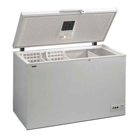
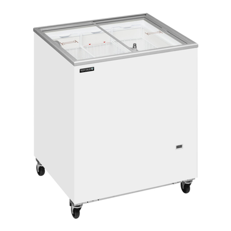
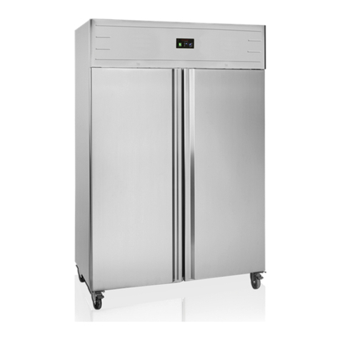
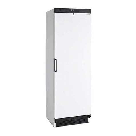
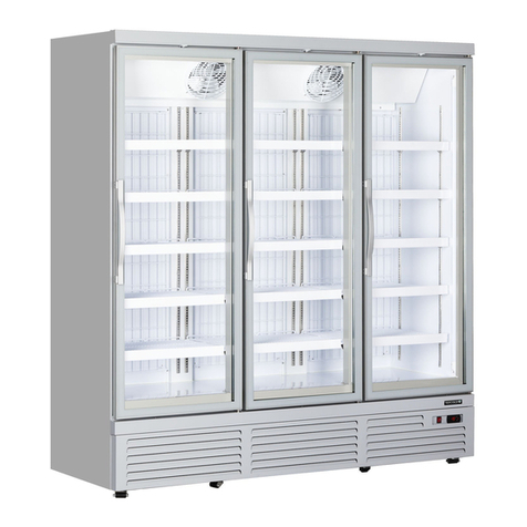
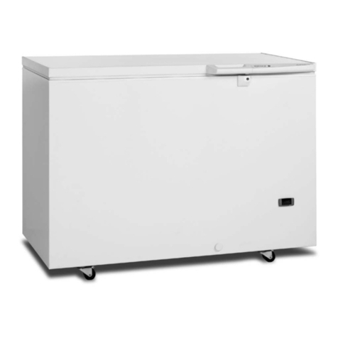
Tefcold SFI Series User manual

Supermarket Type Freezers and Fridges
SFI-Series
ENUser Manual

2
SFI145-Series
SFI185-Series
SFI210-Series
SFI250-Series

3
CONTENTS
1 BASIC INFORMATION ������������������������������������������������������������������������������5
1.1 SYMBOLS ����������������������������������������������������������������������������������������������������������������������5
1.2 INTRODUCTORY PICTURES�������������������������������������������������������������������������������5
1.3 PRODUCER’S AREA OF RESPONSIBILITY��������������������������������������������������6
2 SAFETY INFORMATION AND ENVIRONMENTAL
WARNINS����������������������������������������������������������������������������������������������������������������� 7
2.1 BEFORE OPERATION OF THE EQUIPMENT�����������������������������������������������7
2.2 TECHNICAL SAFETY�����������������������������������������������������������������������������������������������8
2.3 DURING OPERATION OF THE EQUIPMENT ����������������������������������������������8
2.4 WASTE DISPOSAL���������������������������������������������������������������������������������������������������9
3 INSTALLATION���������������������������������������������������������������������������������������������10
3.1 SELECTION OF DEVICE PLACE �����������������������������������������������������������������������10
3.2 TAKING OUT OF PACKAGE��������������������������������������������������������������������������������10
3.3 INSTALLATION �������������������������������������������������������������������������������������������������������� 11
3.3.1 ADJUSTMENT OF ADJUSTABLE STAYS����������������������������������������������������� 11
3.3.2 MULTIPLE DEVICE USE LAYOUT POSITIONS ������������������������������������ 11
3.3.2.1 STAND ALONE USE����������������������������������������������������������������������������������������� 11
3.3.2.2 SINGLE LINE ARRAY ��������������������������������������������������������������������������������������� 11
3.3.2.3 SUCCESSIVE ARRAY��������������������������������������������������������������������������������������� 11
3.3.2.4 HEAD FRIDGE AND ISLAND ARRAY ������������������������������������������������������12
3.4 ELECTRICAL CONNECTIONS��������������������������������������������������������������������������� 12
4 DEVICE USAE���������������������������������������������������������������������������������������������13
4.1 THERMOSTAT ADJUSTMENTS (EWPLUS 978)���������������������������������������13
4.1.1 GENERAL INFORMATION AND INSTRUCTIONS���������������������������������13
4.1.2 SET TEMPERATURE�������������������������������������������������������������������������������������������� 15
4.1.3 AUTOMATIC DEFROST ������������������������������������������������������������������������������������� 15
4.1.4 MANUAL DEFROST���������������������������������������������������������������������������������������������16
4.2 THERMOSTAT ADJUSTMENTS (EWPLUS 971)��������������������������������������16
4.2.1 GENERAL INFORMATION AND INSTRUCTIONS��������������������������������16
4.2.2 SET TEMPERATURE ������������������������������������������������������������������������������������������� 17
4.3 THERMOSTAT ADJUSTMENTS (AKCC 210)����������������������������������������������18
4.3.1GENERAL INFORMATION AND INSTRUCTIONS ���������������������������������18

4
4.3.2SET TEMPERATURE �������������������������������������������������������������������������������������������18
4.3.3MANUAL DEFROST���������������������������������������������������������������������������������������������18
4.3.4CUTOUT ALARM RELAY/RECEIPT ALARM/SEE ALARM CODE��18
4.4 THERMOSTAT ADJUSTMENTS (ERC 112D)����������������������������������������������18
4.4.1GENERAL INFORMATION AND INSTRUCTIONS��������������������������������18
4.4.2GENERAL INFORMATION AND INSTRUCTIONS �������������������������������18
4.4.3MANUAL DEFROST ��������������������������������������������������������������������������������������������18
4.5 THERMOSTAT ADJUSTMENTS (CRA)���������������������������������������������������������19
4.5.1GENERAL INFORMATION AND INSTRUCTIONS�������������������������������� 19
4.5.2– SET TEMPERATURE ������������������������������������������������������������������������������������������ 19
4.5.3– MANUAL DEFROST ������������������������������������������������������������������������������������������19
5 SPECIAL INSTRUCTIONS FOR USE ��������������������������������������������� 20
5.1 DEFROSTING������������������������������������������������������������������������������������������������������������ 20
5.2 GLASS CLEANING�������������������������������������������������������������������������������������������������� 20
5.3 RECOMMENDATIONS FOR ECONOMICAL USE������������������������������������� 21
5.4 LOADING CAPACITY �������������������������������������������������������������������������������������������� 21
6 TURNIN OFF AND CARRYIN THE DEVICE ������������������������22
6.1 TURNING OFF THE DEVICE ������������������������������������������������������������������������������22
6.2 CARRYING THE DEVICE��������������������������������������������������������������������������������������22
7 TURNIN OFF AND CARRYIN THE DEVICE�������������������������23

5
EN
Dear Valued Customer,
e device you have bought is manufactured by taking quality as
priority and designed in order to provide you the best performance.
We advise you to read the explanations oered in this guide
carefully and to act in accordance with the stated rules before
installation of the device and before using the device in order to
ensure the best performance. In case you do not comply with the
explanations stated in this guide, you will go beyond the scope
of your warranty in case of any malfunction of the device.
Please keep this guide to use in the application
transactions that you may need to make later.
1 BASIC INFORMATION
1.1 SYMBOLS
Some significant points in using the
device are made attention grabbing
with symbols. The meaning of these
symbols are stated below in accordance
with their prioritization order. Please
pay attention to these symbols.
WARNIN
It nvolves nformaton
provded n order to prevent
serous damaes that may
result n njures, loss of lfe
and property durn use.
NOTE
It nvolves the nformaton
reardn what to pay
attenton durn use.
SUESTION
It nvolves the nformaton
provded n order to prolon
the devces lfe and to be used
more ecently.
1.2 INTRODUCTORY
PICTURES
All the introductory Images of your
device are presented on the last pages
of this guide. This guide is prepared for
all models, excluding island group head
fridges there are only differences in
sizes for all the models.

6
EN
Please examine the general view of
the device on Image AA.
1. Sldng glass ld
2. Separator
3. Handle
4. Thermostat probe
5. Protectve plastc aganst
mpacts
6. External body
7. Control board
8. Stays
The parts and documents are included
in the package with the device.
•User gude
1.3 PRODUCER’S AREA OF
RESPONSIBILITY
The manufacturer may not be held
responsible in any way for injuries
and damages that may arise in case
of failing to comply with the
aspects stated below. The procedures
performed in breach of the rules
make your equipment out of warranty.
•The assembly and demonstration of
the equipment must be carried out by
the Authorized Service.
•The equipment has freezer, meat
and cooler modes. Do not use the
equipment for purposes other than
its intended use.
•Use the equipment as specified in
this manual (Chapter 2.3).
•Comply with the warning and safety
instructions specified in the manual
(Chapter 1.1).
•Observe the applicable safety
instructions in your region.
•Use only the original spare parts
provided by the manufacturer in order
to maintain the safety conditions.
NOTE
Maintenance, repair and chane
of spare parts operations shall be
carried out by Authorized People.

7
EN
2 SAFETY INFORMATION
AND ENVIRONMENTAL
WARNINS
2.1 BEFORE OPERATION OF
THE EQUIPMENT
It is important to act in
accordance with the aspects stated
below before operation of the
equipment with regards to safety,
performance and energy consumption.
NOTE
e lubricant in the cooler
part of the equipment
may be displaced durin
transportation and transfer
operations. For this reason,
wait minimum 4 to 6 hours
before operatin the
equipment.
The location of assembly of the
equipment affects the performance and
energy consumption of theequipment
(Chapter 3.1). When determining the
location of assembly, the Authorized
Service will provide information and
recommendations; however, the
final decision shall be left to the user.
Depending on the final decision to
be given by the consumer, in case of
experiencing any problem due to the
location of the equipment, all
responsibility shall be borne by the
consumer, and the equipment shall
be considered out of warranty due to
problems that may emerge due to such
positioning.
SUESTION
In order for the equipment to
be used in the most ecient
way, the ambient temperature
where it is located must be
considered. e ambient
temperature in the area where
the equipment will be used
must be 25°C and the humidity
60% R.H.
WARNIN
FIRE HAZARD
If the refrierant as
written on the label at the
bac side of the equipment
is R290, in case of substance
leaae, mae sure that the
necessary ventilation has
been provided in order to
prevent from the mixin of
the inammable as with
air. Because the mentioned
as is environment-friendly
but inammable. In case
of leaae, eep the heat
sources that may lead to
inammation away from the
equipment.

8
EN
NOTE
e internal part of the
equipment must be dry before
placin products inside.
Make sure that there is air circulation
in the motor part.
Please keep in mind that all
electrical appliances are potential
sources of hazard, and pay attention to
all warnings made.
WARNIN
Should be add 200-250 ml
water into the drain pipe
before startin the device
( Imae KK ).
*is clause applies to
models containing the "DF"
statement.
2.2 TECHNICAL SAFETY
R290 refrigerant fluids are
used in the manufacturing of SFI
equipment depending on the orders.
R290 refrigerant fluid is
environment friendly but inflamma ble.
Therefore, in handling and mounting
operations of the equipment, follow the
steps below if the cooler or electrical
equipment has been damaged.
•If there is any kind of source such
as fire, sparkle etc. that may lead to
in flammation at the environment
where the equipment is located,
keep your equipment away from such
sources. Otherwise, fire, explosion, etc.
may be experienced.
•Plug out the equipment and
ventilate the environment where the
equipment is located.
•Please contact the Authorized
Service.
The refrigerant gasses in this
equipment slightly increase the sound
of operation of the compressor. You
may hear the sound of air circulation
to gether with this sound. This
situation is normal and it does not
affect the working performance of the
equipment.
The outer frame of the equipment
may get warm during operation. This
situation is normal and it is caused by
the design of the equipment.
2.3 DURING OPERATION OF
THE EQUIPMENT
This equipment is manufactured to
be used in stores such as supermarkets
etc. It is important to comply with the
articles stated below about the use of
the equipment with regards to safety,
performance and energy consumption.
•Your equipment is designed for
use in indoor environments. Our
company shall not be responsible due to
problems that may arise in the case
that you use your equipment in outdoor
environments.
•The equipment can operate in
freezer, meat and cooler mode options.
Do not use the equipment for purposes
other than its intended use.
9
EN
WARNIN
EXPLOSION HAZARD
Never use electrcal
applances nsde the
equpment.
•In case that the equipment is
used by children and people lacking
knowledge (people with limited
physical, emotional or cognitive
skills), it may lead to some risks and
dangerous situations. In order to
prevent such risks, persons who may
be exposed to danger must use the
equipment with the guidance and under
the control of the responsible person.
•Keep children younger than 8 years
old away from the equipment and
prevent them from using the
equipment. Children should be
supervised to ensure that they do not
play with the appliance.
•Carry out the layout,
installation and cleaning of the
equipment asspecified in this manual.
As the result of applications other than
specified in this manual, your
equipment may be damaged and it may
go out of warranty (Chapter 3).
•If the equipment is used in
accordance with the climatic
conditions for which it is designed, it
will provide the best performance. This
equipment is designed to be used in
indoor environments. According
to EN 23953-2, it must be used in
environments to provide Climate Class 3
(25°C– 60% R.H.).
2.4 WASTE DISPOSAL
This equipment is compatible with
Waste Electrical and Electronic
Equipment (WEEE) Control
Regulations.Within the scope of this
regulation, it may be recycled by
Licensed Companies or may be
disposed of under conditions consonant
with the environment.
This equipment is not an
invaluable waste. You may protect the
environment and natural resources
by enabling reuse of valuable raw
materials. If the equipment is worn and
may not be reused, please follow the
steps below.
•Plug out the equipment.
•Cut the equipment’s electric
cable and separate itfromtheequipment
together with the plug.
•Get information about the Waste
Electrical and Electronic Equipment
(WEEE)collectingpoints ortheLicensed
Companies from your municipality.

10
EN
3 INSTALLATION
3.1 SELECTION OF DEVICE
PLACE
The working environment is very
significant in order for the device
to work smoothly. Ensure that the
conditions stated below are provided
with regards to the place the device
will be installed in for the cooling
performance and energy consumption
to stay within the proper values.
•A bowless, flat and solid ground
shall be chosen for the device.
•The size of the room where the
equipment will be used must be 1 m3
for each 8g of refrigerant. The amount
of refrigerant that your equipment
contains is written on the label on
the buttom left part back of cabin
(Image JJ).
•The ventilating slits of the
device shall not be covered. There shall
be at least 150 mm distance between the
device’s ventilating slits and the wall.
•There shall be a grounded and solid
plug present close to the device.
•Device shall be placed at least 1
meter away from heat sources (oven,
cooker, stove, radiator etc.)
•Device shall be placed where there
is no direct sunlight.
•Device shall be placed away from
places where there is air stream (against
the air condition openings, under fans,
at doorsteps or close to windows etc.).
SUESTION
Comply with the Authorized
Persons uidance and
suestions for place selection
in order to et the best
performance from the device.
3.2 TAKING OUT OF PACKAGE
Do not use sharp/piercing
materials to open the package. Take
the device out of the package by
taking the warnings, which are
prepared suitable to all package
materials, stated below into
consideration.
Dismantle the cable ties around
the package and take the cardboard
package off the device. Take out the
styrofoam materials that are at the
top and on the side of the device.
Dismantle the tie, which is under
the device and attached with
pallet, in order to take the device off
the pallet. Get in front of the device
as shown in Image BB push the device
backwards by applying force.

11
EN
NOTE
Pacain materials may
be danerous for children.
Preserve the pacain
materials in a place where
children cannot reach.
Pacain materials are
suitable for recyclin and
may be reused. us, dispose
of the pacae materials
in accordance with waste
disposal instructions or
by consultin to your
municipality and in a way that
will not damae environment.
3.3 INSTALLATION
3.3.1 ADJUSTMENT OF
ADJUSTABLE STAYS
Balance the device by way of a
water gauge with regards to the
width and length. You may carry out
the balancing with the help of the
stays on the device. You may adjust
the balance with the help of a key
because of the device’s weight.
As is shown in Image CC, it may be
adjusted to a level you d esire and
you may raise it to 13 mm in maximum.
Wear protective gloves while carry
out the balancing operation.
3.3.2 MULTIPLE DEVICE USE
LAYOUT POSITIONS
3.3.2.1 STAND ALONE USE
Pay attention that there is at
least 150 mm distance between the
wall and the device (back part). The
device may have a contact with the
wall on the side. A visual regarding
the device’s lay-out is presented on
Image DD .
3.3.2.2 SINGLE LINE ARRAY
Pay attention that there is at least
150 mm distance between the wall
and the device (back part). In case you
will line up more than one market
fridge side by side, it is not necessary
to leave an air gap between them.
A visual regarding the device’s
lay-out is presented on Image EE .
3.3.2.3 SUCCESSIVE ARRAY
In case you will place more than
one market devices back to back, you
shall definitely use special profiles
and lids. Thus, by means of the
profiles and lids, there will be at
least 150 mm distance between two
back-to-back market devices. A visual
regarding the device’s lay-out is
presentedon Image FF .
*You may all the necessary original
spare parts and island assembling guide
from Authorized People.

12
EN
3.3.2.4 HEAD FRIDGE AND
ISLAND ARRAY
It is the island group consisting
of head fridges, which are placed
at the head of the group, in addition
to the back-to-back array. It is not
necessary to leave air gaps between
head fridges and other fridges. A
visual regarding the device’s lay-out
is presented on Image GG.
WARNIN
FIRE HAZARD
You denitely shall leave
the ventilatin slits
and surroundins open
within the scope of the
rules stated on the uide.
Denitely do not prevent
air ow. Denitely do not
cover.
3.4 ELECTRICAL
CONNECTIONS
This device works with 220-240V/
50-60 Hz, 110-127/60 Hz alternating
current. Check this value from the label
at the back of the device (Image JJ). The
aspects you shall pay attention to while
using the device are stated below:
•The plug shall be easily accessed
also after the device is placed.
•Signified voltage shall be equivalent
to grid voltage.
•Extension cables or multi-plugs
shall not be used.
•Damaged electric cable shall be
replaced by a professional electricity
expert.
•A grounded socket, which is
protected by a fuse with sufficient
capacity (that has 10-16 A strength),
shall be used for the device.
•In case there is an electrical
problem with the device, the device
shall not be used until it is repaired.
Electric shock may occur.
WARNIN
FIRE HAZARD
Before accessin to the
connection terminals, all
circuits power must be
disconnected.

13
EN
4 DEVICE USAE
4.1 THERMOSTAT ADJUSTMENTS (EWPLUS 978)
4.1.1 GENERAL INFORMATION AND INSTRUCTIONS
The explanations regarding the symbols on the thermostat and general
information about the settings are given below.
NOTE
When the device starts worin, chec whether screen and liht
are worin or not.
Thermostat visual is presented on Image H1H1 .
Keys;
1-[]/Defrost: Press and release, increases the sliding values between Menu
options or enables transition. When you press it at least for 5 seconds, Manuel
Defrost Loop starts.
2-[ ]/Light: internal menu status, decreases the sliding values between menu
options or enables transition. When you press it at least for 5 seconds, the light
turns on/off.
3- [ ]/(Esc): Press and release, enables to return to the previous menu level
and to approve parameter value. When you press it at least 5 seconds, opens the
programming menu. Approves the commands (Standby on).
4-[ ]/(Enter) : Press and release, shows alarms and opens sub menus
(if any). Approves the commands.

14
EN
Reduced SET / Economy LED
Permanently on: Energy
Savng actve
Flashng: Reduced set actve
Quck ashng: Access to
level2 parameters
O: Otherwse
Fans LED
Permanently on: Fans actve
O: Otherwse
Compressor LED
Permanently on: Compressor
actve
Flashng: Delay, protecton or
actvaton blocked
O: Otherwse
Defrost LED
Permanently on: Defrost
actve
Flashng: Actvated manually
or from DI
O: Otherwse
Aux LED
Permanently on: Aux output
actve
Flashng: Deep coolng Cycle
actve
O: Aux output not actve
Alarms LED
Permanently on: alarm actve
Flashng: alarm acknowledged
O: otherwse
°C LED
Permanently on: °C settng
(dro = 0)
O: otherwse
°F LED
Permanently on: °F settng
(dro = 1)
O: otherwse
Digital thermostats contain many parameters within themselves. Your
thermostat has factory settings by default and does not require any adjust-
ment, however, the user has the option to change the mode on EWPlus 978
thermostat. EWPlus 978 thermostat may operate in three different modes.
1. Freezer
2. Meat Mode
3. Cooler

15
EN
AP1 AP2 AP3
Freezer Mode Meat Mode Cooler Mode
You may change the mode according to the instructions below:
•Press the key [ ] for 5 seconds while the equipment runs. You will see the
word “OFF” on the screen and the equipment will turn off all functions except of
lighting.
•Press and hold the key [ ] for another 5 seconds. The equipment will switch
to “ON” position. The compressor symbol will be seen on the screen.
•Press and hold the key [ ] for 5 seconds again within 15 seconds. (If no
operation is done within this period, the mode change will be cancelled.) “AP1” will
be seen on the screen.
•AP1-AP2-AP3 modes can be seen with the keys [ /] . Press key [ ]
once when the mode you want to choose is on the screen. The letter "y" will be seen
on the screen and the desired mode will be selected.
•The modes that you may select are as in the table below.
Example : In case the mode you want to choose is Meat mode, then when you
press [ ] key when AP2 is written on the screen, then you switch to Meat mode.
NOTE
In case you thn that there s a problem wth reards to the
operaton of the devce or wth reards to dtal thermostat
settns, please as for support from the Authorzed Person.
4.1.2 SET TEMPERATURE
To display the Setpoint value press the [ ] key when the 'SEt' label is
displayed. The Setpoint value appears on the display. Please again press the ( ). To
change the Setpoint value, press the [ ] and [ ] keys within 15 seconds. Press
[]to confirm the modification. Press the( ) key to exit setting.
4.1.3 AUTOMATIC DEFROST
Automatic defrost is available for DF models. The device is programmed
to defrost automatically in accordance with the mode the device is working.
There will be some frost deposit while the device is working due to the humidity
of the environment. Because of defrost, the generated frost deposit will be
melt and the device will work with maximum productivity. Defrost ranges in
accordance with the modes are presented on the table below.

16
EN
Cooler Mode: 12 Hours
Freezer Mode: 24 Hours
Et(Meat)Modu: 12 Hours
4.1.4 MANUAL DEFROST
Hold down the [ ]key for longer than 5 seconds. It is only activated if the
temperature conditions are fulfilled. Otherwise, the display will blink 3 times to
indicate that the operation will not be performed.
4.2 THERMOSTAT ADJUSTMENTS (EWPLUS 971)
EWPlus 971 thermostat is used for D (freezer without defrost) models.
4.2.1 GENERAL INFORMATION AND INSTRUCTIONS
Thermostat vsual s presented on Image H1H1 .
Keys;
1- []: Press and release, ncreases the sldng optons among menu optons and
enables transton.
2-[]/Light: Internal menu status, reduces sldng values among menu optons
or enables transton. When you press for 5 seconds, the Lght turns on/off.
3- []/(Esc): Press and release, return to the prevous menu and approval
of parameter values. When you press at least for 5 seconds, all the functons are
turned off excludng the lghts (Standby on)
4-[]/(Enter): Press and release, dsplays the alarms and opens sub menus
(f any). When you press for 5 seconds, opens programmng menus. Approves the
commands.

17
EN
Reduced SET / Economy LED
Permanently on: Energy
Savng actve
Flashng: Reduced set actve
Quck ashng: Access to
level2 parameters
O: Otherwse
Fans LED
Permanently on: Fans actve
O: Otherwse
Compressor LED
Permanently on: Compressor
actve
Flashng: Delay, protecton or
actvaton blocked
O: Otherwse
Alarms LED
Permanently on: alarm actve
Flashng: alarm acknowledged
O: otherwse
Aux LED
Permanently on: Aux output
actve
Flashng: Deep coolng Cycle
actve
O: Aux output not actve
°F LED
Permanently on: °F settng
(dro = 1)
O: otherwse
°C LED
Permanently on: °C settng
(dro = 0)
O: otherwse
NOTE
Your thermostat s set on factory defaults and does not requres
any adjustment. Only freezer wthout defrost mode s avalable
for EWPlus 971 thermostat.
4.2.2 SET TEMPERATURE
To display the Setpoint value press the [ ] key when the 'SEt' label is
displayed. The Setpoint value appears on the display. Please again press the ( ). To
change the Setpoint value, press the [ ] and [ ] keys within 15 seconds. Press
[]to confirm the modification. Press the( ) key to exit setting.

18
EN
4.3 THERMOSTAT
ADJUSTMENTS (AKCC 210)
4.3.1GENERAL INFORMATION
AND INSTRUCTIONS
Thermostat vsual s presented on
Image H2H2 .
Keys;
1-Short press, acknowledge alarms
or see control status. Long press, setup
menu.
2-Press, change temperature set point
3-Short press, see defrost sensor
temperature. Long press, start a defrost
cycle.
4.3.2SET TEMPERATURE
•Push the middle button until the
temperature value is shown.
•Push the upper or the lower button
and select the new value.
•Push the middle button again to
conclude the setting.
4.3.3MANUAL DEFROST
Reading the temperature at defrost
sensor.
•Push short the lower button.
Manuel start or stop of a defrost.
• Push the lower button for four
seconds.
4.3.4CUTOUT ALARM RELAY/
RECEIPT ALARM/SEE ALARM
CODE
•Push short the upper button.
If there are several alarm codes they
are found in a rolling stack. Push the
uppermost or lowermost button to scan
the rolling stack.
4.4 THERMOSTAT
ADJUSTMENTS (ERC 112D)
4.4.1GENERAL INFORMATION
AND INSTRUCTIONS
The explanations regarding the
symbols on the thermostat and general
information about the settings are given
below.
Thermostat visual is presented on
Image H3H3 .
1) [ ] : Defrost Key
2) [ ] : Stand by Key
3) [ ] : Up Key
4) [ ]: Down Key
4.4.2GENERAL INFORMATION
AND INSTRUCTIONS
Push the [ ] untl thetemperature
value is shown or push the [ ] until the
temperature value is shown.
4.4.3MANUAL DEFROST
Manuel start or stop of a defrost.
•Push the [ ].

19
EN
4.5 THERMOSTAT ADJUSTMENTS (CRA)
4.5.1GENERAL INFORMATION AND INSTRUCTIONS
The explanations regarding the sybols on the thermostat and general informtion
about the settings are given below. Thermostat visual is presented on Image H4H4 .
1) [
SET
4s
] - Dsplays the control setpont. Ext the control setpont and save the
changes.
2) [
AUX
] - Cancel and return to standard mode. Swtch furnture lghtng on/off.
Actvate/deactvate AUX output.
3) [
FNC
] - Set a lower value. Actvate/deactvate energy-savng mode.
4) [ ] - Set a hgher value. Actvate manual defrostng.
[]- Compressor s swtched on
[] - Defrostng n progress
[] - Evaporator fan s swtched on
[
HACCP
] - Stored HACCP alarm
[
°C
] - Temperature unt s the degree Celsus
[
°F
] - Temperature unt s the degree Fahrenhet
[
AUX
]- Furnture lghtng
[]- Devce s n standby mode
[]- Energy-savng mode s actve
[]- Compressor requres mantenance
4.5.2 SET TEMPERATURE
To set the operatng temperature of your devce, press the [
SET
4s
] key.
The Setpoint value appears on the display.
Use the [ ]/[
FNC
] keys to set the
desired value.Press the [
SET
4s
]
to confirm the modification.
4.5.3 MANUAL DEFROST
Hold down the
[ ] key for 5 seconds on the thermostat.

20
EN
5 SPECIAL INSTRUCTIONS FOR USE
Perform the external cleanng of your equpment wth cotton cloth and warm
water. Prevent the cleanng water from penetratng nto the lghtng parts of the
equpment durng cleanng.
•Clean the cover seal only by using clean soapy water. The plastic components
of your equipment might get damaged due to cleaning with chemical cleaners
(such as thinner, etc.).
•Always keep the ld seals (gasket) located on the edges of the lds clean, n case
there s any damage on the seals, you may call Authorzed People.
•In order not to clogging the water outlet of the device, this outlet
channel should always be cleaned from dirt. The residues around this hole should
be cleaned at regular intervals.
5.1 DEFROSTING
In case the internal walls of the device is excessively frosted, this condition will
lead to the decrease of the cooling capacity and to consumption of more energy.
Clean the frosted places with the shaving knife supplied with the device, without
damaging the walls. In case frosting is too much, place the products inside the
device in an appropriate place where they will not be ruined. Then, plug out the
device. Normally, the frosting shall be melted within two (2) hours. After the
melting process, wipe the internal wall of the device with a dry cloth and pay
attention that it does not stay wet. Operate your device as hollow until "-18"
appears on your thermostat screen. When "-18" appears on the screen, you can
upload your products. If there is your device model name containing 'DF', see
sections titled ''Manual Defrost’’.
5.2 GLASS CLEANING
Attention must be paid especially to the aspects stated below concerning the
glass surface of SFI equipment, which is plated, located inside and which has high
heat reflection feature and has low emission level (Low-E);
• The cleanng of the plated part nsde the equpment must be made when the
equpment s off.
• Hard or sharp objects made of metal (glass scraper, glass knfe, steel wool etc.)
that may damage the glass surfaces must not be used.
• Make sure that the glass surfaces to be cleaned are exposed to too much water
and that they are thoroughly dred after surface cleanng.
This manual suits for next models
3
Table of contents
Other Tefcold Freezer manuals

Tefcold
Tefcold CF110 User manual

Tefcold
Tefcold FR205-I User manual

Tefcold
Tefcold IC-SC Series User manual

Tefcold
Tefcold NF2500G User manual

Tefcold
Tefcold BLC3 User manual

Tefcold
Tefcold ATOM MAXI MK2 User manual

Tefcold
Tefcold CF77 User manual

Tefcold
Tefcold CC45-I Operation instructions

Tefcold
Tefcold LDP900F Technical manual

Tefcold
Tefcold UFSC370SD User manual
Popular Freezer manuals by other brands

Electrolux
Electrolux EC 5109N OPERATING AND INSTALLATION Manual

AEG
AEG SANTO 75320 DT user manual

Pelgrim
Pelgrim PVS24102N Instructions for use

Crosley
Crosley CFC09LW Use & care manual

CDA
CDA PC900 Installation, use and maintenance

Silver King
Silver King SKFB27 Technical manual and replacement parts list