TEGA 4000-S User manual
Manuel utilisateur • User’s Manual • Bedienungsanleitung
Version December 2013
TEGA Muhendislik Sanayi ve Ticaret A.Ş.
Organize Sanayi Bölgesi Kırım Hanlığı Cad. No:1
Ayaş Yolu 25. km
06930 Sincan Ankara
4000-S
+90 (0)312 267 18 76
+90 (0)312 267 18 77
http://www.tega.com.tr


4000-S
Version December 2013 3
English
TEGA Muhendislik Sanayi ve Ticaret A.Ş.
06930 Sincan Ankara,
Turkey
Contents
1 Introduction ........................................................................................................................... 5
2 Safety Messages ................................................................................................................... 5
2.1 Using the Correct Connection Terminal ............................................................................. 5
2.2 Improper Use of the Welding and Power Supply Cables ................................................ 5
2.3 Securing the Fitting and the Joint ...................................................................................... 5
2.4 Cleaning the Product ............................................................................................................ 5
2.5 Opening the Unit ................................................................................................................... 6
2.6 Extension Cables on the Worksite ...................................................................................... 6
2.7 Checking the Product for Damage ..................................................................................... 6
2.8 Data Interface Cover Cap .................................................................................................... 6
2.9 Power Supply Specications ............................................................................................... 6
2.9.1 Mains Power Supply ............................................................................................................. 6
2.9.2 Generator Power Supply ...................................................................................................... 6
2.10 Integrity of Welding Reports in Memory ........................................................................... 7
3 Service and Repair ............................................................................................................... 7
3.1 General ................................................................................................................................... 7
3.2 Transport, Storage, Shipment ............................................................................................. 7
4 Principles of Operation ........................................................................................................ 7
5 Check-out and Operation ..................................................................................................... 8
5.1 Turning the Welding Unit on ................................................................................................ 8
5.2 Entering the Welder ID Code ............................................................................................... 8
5.3 Connecting the Fitting .......................................................................................................... 9
5.4 Reading the Fitting Code with a Handheld Scanner ....................................................... 9
5.5 Starting the Welding Process ............................................................................................. 9
5.6 Welding Process ................................................................................................................... 9
5.7 End of Welding ....................................................................................................................10
5.8 Aborted Welding Process ..................................................................................................10
5.8 Cooling Time ........................................................................................................................10
5.10 Returning to the Start of Parameter Input ......................................................................10
5.11 Viewing Welding Reports after the Welding Process ....................................................10
6 Additional Information in the Welding Report ...............................................................10
6.1 Entering Preformatted and User-dened Traceability Data .........................................10
6.2 Entering or Changing the Job Number .............................................................................11
6.3 Entering or Changing Additional Data .............................................................................11
6.4 Entering the Fitting Traceability Code ..............................................................................11
6.5 Entering the Pipe Codes and the Installing Company ...................................................11
7 Entering Welding Parameters Manually ..........................................................................12
7.1 Manually Entering Welding Voltage and Time ................................................................12
7.2 Entering the String of Numbers ........................................................................................12
8 Downloading the Reports ..................................................................................................12
8.1 Selecting the File Format ..................................................................................................12
8.2 Downloading All Reports ...................................................................................................13
8.3 Downloading by Commission Number, Date or Report Range ....................................13
8.4 Understanding the Report Download Process ...............................................................13
8.5 Deleting Data from Memory .............................................................................................13
8.6 Keeping Data in Memory ...................................................................................................13
9 Dedicated Welding Unit Information ...............................................................................13
9.1 Displaying Next Service and Other Characteristics of the Welding Unit.....................13
9.2 Measuring Resistance ........................................................................................................14
9.3 Overheating Switch .............................................................................................................14
9.4 Indication of Power Supply Failure at the Last Welding ...............................................14

4000-S
Version December 2013
4 English
TEGA Muhendislik Sanayi ve Ticaret A.Ş.
06930 Sincan Ankara,
Turkey
10 Conguring the Welding Unit ............................................................................................14
10.1 Understanding the “Settings” Sub-menu ........................................................................15
10.1.1 Selecting the Display Language .......................................................................................15
10.1.2 Setting the Clock .................................................................................................................15
10.1.3 Setting the Buzzer Volume ................................................................................................15
10.2 Understanding the “Recording” Sub-menu .....................................................................15
11 Self-Monitoring Functions Overview .................................................................................16
11.1 Errors During Data Input ....................................................................................................16
11.1.1 Code Error ............................................................................................................................16
11.1.2 No Contact ...........................................................................................................................16
11.1.3 Low Voltage .........................................................................................................................16
11.1.4 Overvoltage ..........................................................................................................................16
11.1.5 Overheated ..........................................................................................................................16
11.1.6 System Error ........................................................................................................................16
11.1.7 Temperature Error ...............................................................................................................16
11.1.8 Temperatur Sensor Defective ...........................................................................................16
11.1.9 Clock Error............................................................................................................................16
11.1.10 Next Service .........................................................................................................................16
11.1.11 Input Error ............................................................................................................................ 17
11.1.12 Memory Full ......................................................................................................................... 17
11.1.13 Downloaded Cancelled ......................................................................................................17
11.2 Errors During Welding ........................................................................................................ 17
11.2.1 Low Voltage ......................................................................................................................... 17
11.2.2 Overvoltage .......................................................................................................................... 17
11.2.3 Resistance Error .................................................................................................................. 17
11.2.4 Frequency Error ...................................................................................................................17
11.2.5 Voltage Error ........................................................................................................................17
11.2.6 Low Current..........................................................................................................................17
11.2.7 Excess Current ..................................................................................................................... 17
11.2.8 Emergency Off .....................................................................................................................17
11.2.9 Heater Coil Error ..................................................................................................................17
11.2.10 Power Supply Failure at Last Welding .............................................................................18
12 Technical Specications ....................................................................................................18
13 Service and Repair Contact ...............................................................................................18
14 Accessories/Parts for the Product ...................................................................................18

4000-S
Version December 2013 5
English
TEGA Muhendislik Sanayi ve Ticaret A.Ş.
06930 Sincan Ankara,
Turkey
1 Introduction
Dear Customer:
Thank you very much for purchasing our product. We are confident that it
will meet your expectations.
The TEGA 4000–S Welding Unit is designed exclusively for welding plastic
pipe fittings according to the electrofusion process.
The product was manufactured and checked according to state-of-the-art
technology and widely recognized safety regulations and is equipped with
the appropriate safety features.
Before shipment, it was checked for operation reliability and safety. In
the event of errors of handling or misuse, however, the following may be
exposed to hazards:
• the operator’s health,
• the product and other hardware of the operator,
• the efficient work of the product.
All persons involved in the installation, operation, maintenance, and service
of the product have to
• be properly qualified,
• operate the product only when observed,
• read carefully and conform to the User’s Manual before working with
the product.
Thank you.
2 Safety Messages
2.1 Using the Correct Connection Terminal
Use the appropriate connection terminal that is compatible with the fit-
ting type used. Be sure the contact is firmly established and do not use
connection terminals or terminal adapters that are burnt or not designed
for the intended use.
2.2 Improper Use of the Welding and Power Supply Cables
Do not carry the product by its cables and do not pull the power cord to
unplug the unit from the socket. Protect the cables against heat, oil, and
cutting edges.
2.3 Securing the Fitting and the Joint
Use positioner clamps or a vice to secure the fitting and the joint to be
made before welding. The fitting manufacturer’s installation instructions,
local and national regulations have to be respected in all cases.
A welding process must never be repeated with the same fitting, since this
may cause parts under power to be accessible to the touch.
2.4 Cleaning the Product
The product must not be sprayed with or immersed in water.
4000-S
Version December 2013
6 English
TEGA Muhendislik Sanayi ve Ticaret A.Ş.
06930 Sincan Ankara,
Turkey
2.5 Opening the Unit
Caution
The cover of the product may be removed only by specialized
staff of the manufacturer or of a service shop properly trained
and approved by it.
2.6 Extension Cables on the Worksite
To extend power cord length, use exclusively properly approved extension
cables that are labeled as such and have the following conductor sec-
tions:
up to 20 m: 1.5 mm² (2.5 mm² recommended); Type H07RN-F
over 20 m: 2.5 mm² (4.0 mm² recommended); Type H07RN-F
Caution
When using the extension cable, it has always to be rolled off
completely and lie fully extended.
2.7 Checking the Product for Damage
Before every use of the product, check safety features and possibly existing
parts with minor damage for proper function. Make sure that the push-on
connection terminals work properly, that contact is fully established, and
that the contact surfaces are clean. All parts have to be installed correctly
and properly conform to all conditions in order for the product to function
as intended. Damaged safety features or functional parts should be properly
repaired or replaced by an approved service shop.
2.8 Data Interface Cover Cap
The dust cap for the interface has to cover the port during operation, in
order to keep humidity and contaminations away.
2.9 Power Supply Specications
2.9.1 Mains Power Supply
Utility suppliers’ wiring requirements, occupational safety rules, applicable
standards, and national codes have to be respected.
Caution
When using power distributions on the worksite, rules for the
installation of earth-leakage circuit breakers (FI) have to be re-
spected, and operation requires an installed breaker.
Generator or mains power fuse protection should be max. 16 A (slow blow).
The product has to be protected against rain and humidity.
2.9.2 Generator Power Supply
The required nominal generator capacity as determined by the power supply
requirement of the largest fitting to be welded depends on the power supply
specifications, the environment conditions, and the generator type itself
including its control/regulation characteristics.
Nominal output power of a generator 1-phase, 220 - 240 V, 50/60 Hz:
d 20 ........d 160 3.2 kW
d 160 .......d 450 4 kW mechanically regulated
5 kW electronically regulated
Start the generator first, then connect the welding unit. The idle voltage
should be set to approx. 240 volts. When turning the generator off, discon-
nect the welding unit first.
Important
The working output power of the generator decreases by about
10% per 1,000 m of altitude. During the welding process no other
device connected to the same generator should be operated.
4000-S
Version December 2013 7
English
TEGA Muhendislik Sanayi ve Ticaret A.Ş.
06930 Sincan Ankara,
Turkey
2.10 Integrity of Welding Reports in Memory
When transferring welding reports to a USB stick, always be sure to wait
until the display shows the “Download finished” message before you discon-
nect the USB stick from the product. If you disconnect it too early, the unit
may ask you whether you want to delete the reports in memory, although
they were not properly transferred. In this case, if you delete the contents
of the report memory, the welding reports would be irrevocably lost and
would not be available elsewhere either.
3 Service and Repair
3.1 General
As the product is used in applications that are sensitive to safety consid-
erations, it may be serviced and repaired only by the manufacturer or its
duly authorized and trained partners. Thus, constantly high standards of
operation quality and safety are maintained.
Failure to comply with this provision will dispense the manufacturer from
any warranty and liability claims for the product, including any consequen-
tial damage.
When serviced, the unit is upgraded automatically to the technical specifi-
cations of the product at the moment it is serviced, and we grant a three-
month functional warranty on the serviced unit.
We recommend having the product serviced at least every twelve
months.
3.2 Transport, Storage, Shipment
The product ships in its case in a cardboard box. Its case protects the prod-
uct from humidity and environmental agents. Whenever it is not used and
to forward it, keep the case of the product closed.
4 Principles of Operation
The TEGA 4000–S allows welding electrofusion fittings that feature a bar
code. Every fitting is provided with a tag with one or two bar codes on it.
The structure of this code is internationally standardized. The first code,
encoding the data on proper welding, complies with ISO TR 13950, the
second code, if present, encoding the component traceability data, com-
plies with ISO 12176-4.
The welding control program supports certain of the extended traceability
data encoded under the ISO 12176-4 standard, e.g., the fitting traceability
code. To use this feature, the desired data have to be enabled in the con-
figuration menu, at “Recording” (see Sect. 10.1).
The welding parameters can also be entered manually. The microprocessor-
controlled TEGA 4000–S Welding Unit
• controls and monitors the welding process in a fully automated fash-
ion,
• determines welding duration depending on ambient temperature,
• shows all information on the display in plain text.
All data that are relevant for the weld or for traceability are saved to the
internal memory and can be sent to a USB stick.
4000-S
Version December 2013
8 English
TEGA Muhendislik Sanayi ve Ticaret A.Ş.
06930 Sincan Ankara,
Turkey
Welding data transfer is enabled through an interface of the USB A type,
which is compatible with a USB stick.
Further Optional Accessories
• PC software for downloading and archiving data on PC (for all common
Windows operating systems)
• USB stick for data transfer from the welding unit on the worksite to the
printer or PC in your office (see details at the end of this booklet)
5 Check-out and Operation
• To operate the welding unit, be sure that it is set on a proper, level
surface.
• Be sure that power supply/generator protection is 16 A (slow blow).
• Plug the power supply cord into the mains power supply or the genera-
tor.
• Read and comply with the User’s Manual of the generator, if appli-
cable.
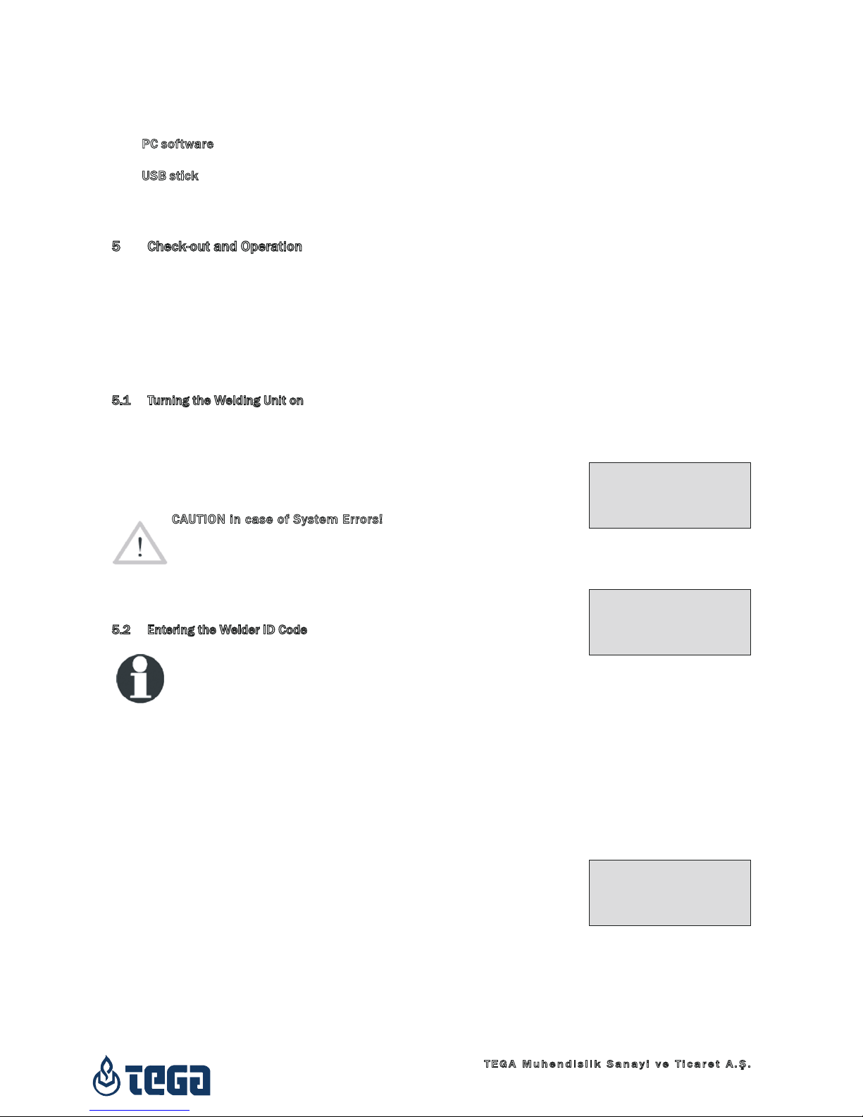
5.1 Turning the Welding Unit on
After connecting the power supply cable to mains power or a generator,
turn the welding unit on using the On/Off switch. This causes Display 1 to
show.
Then the screen changes to Display 2.
Caution
CAUTION in case of System Errors!
If during the auto-test that the unit performs at start-up, an error
is detected, a “System Error” message shows on the display.
When this happens, the welding unit has to be disconnected im-
mediately from the power suppy and the fitting, and it has to be
shipped to the manufacturer for repair.
5.2 Entering the Welder ID Code
Info
The alphanumeric keypad is designed and works like the keypad
of a common mobile phone without touch screen display. All
characters found on a key can be “browsed” by pressing that key
repeatedly at short intervals. As soon as “browsing” generates
the desired character on the screen, wait a little longer until
you press the next key to use the displayed character. The first
character always is the number on the respective key, then the
letters or marks in the order on the key, i. e., for instance, with
the key “2 | a | b | c” the 1st keypress brings up “2,” the 2nd “a,”
the 3rd “b,” and the 4th brings up “c.” By default, lower-case let-
ters appear on the screen. To enter upper-case letters, hold down
the ñ key while selecting the appropriate letter by one or several
keypresses.
The welding unit can be configured to ask for the welder identification
code before the fitting code is entered. The display screen then shows
the message “Enter Welder Code.” (Later this screen can be accessed by
a quick access routine; see Sect. 6.1.) The numeric code can be entered
either by reading it from a tag with the scanner or by using the alphanu-
meric keypad.
When the welder code is read from a bar code using the scanner, an audible
signal confirms this and the screen shows the read code and switches to
the next input display. When the code is entered manually, it is saved by
Display 1
Display 2
********************
TEGA
Tega 4000-S
********************
Enter Barcode
14:32:22 21.10.12
Supply V.: 230V 50Hz
No Contact
Display 3
** Welder ID Code **
++++++++++++++++++++
++++++++++
4000-S
Version December 2013 9
English
TEGA Muhendislik Sanayi ve Ticaret A.Ş.
06930 Sincan Ankara,
Turkey
pressing the START/SET key. If the code entered is not correct, a “Code
Error” message appears; check the sequence of numbers and correct as
needed. If the code entered is correct, it is saved to system memory and
inserted into the welding reports to be printed.
Only an ISO standard-compliant welder identification code is accepted by
the unit. If the welder code feature is disabled, the input screen for the
welder code will not show.
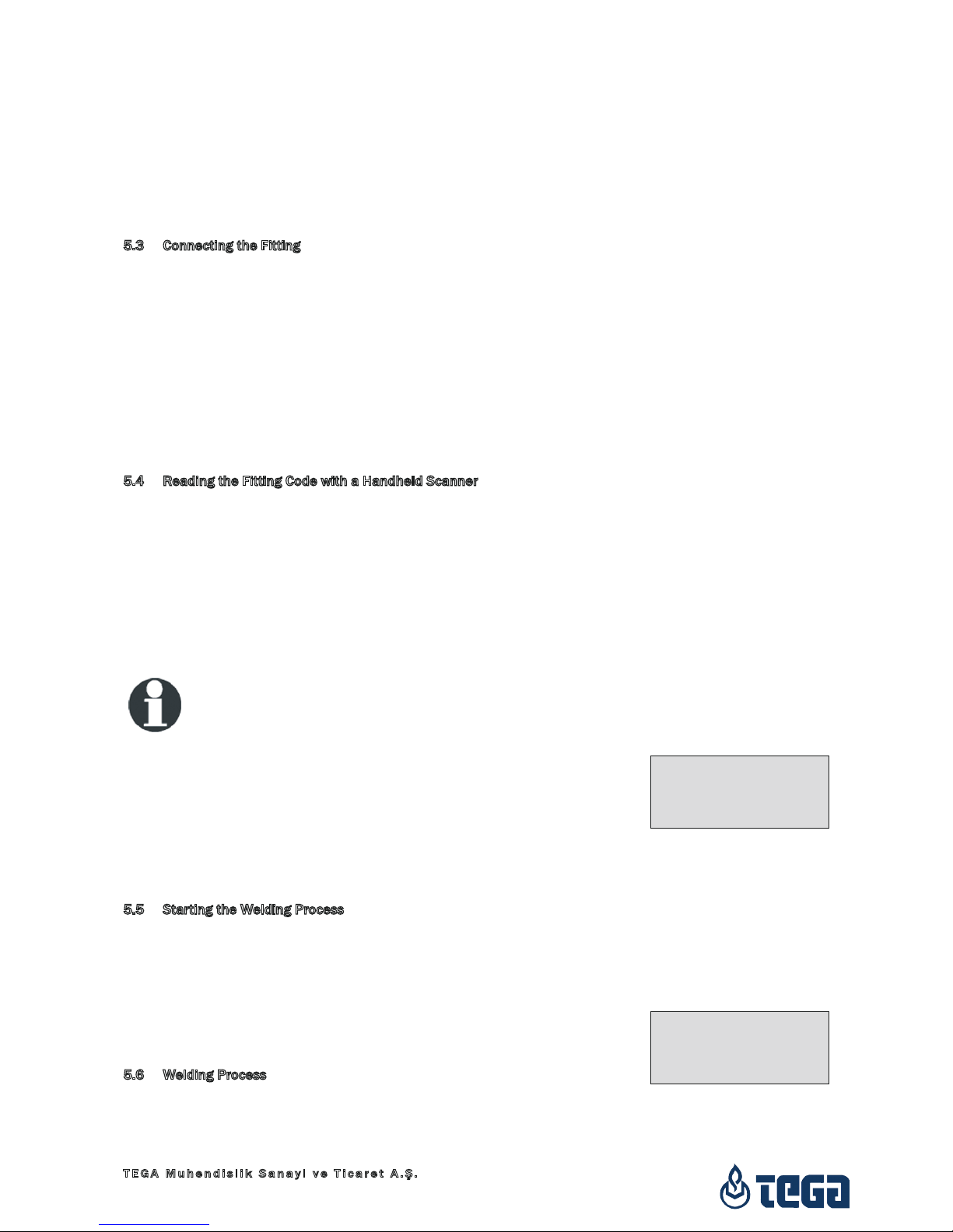
5.3 Connecting the Fitting
Connect the connection terminals to the fitting and check for proper con-
tact. Use terminal adapters if needed. The contact surfaces of the cable
connection terminals or adapters and the fitting have to be clean. Dirty
terminals may lead to improper welding and also to overheated and fused
connection terminals. Protect the cable connectors against getting dirty at
all times. Terminals and push-on adapters should be considered consum-
ables and, therefore, have to be checked before every welding operation
and replaced if damaged or dirty.
When the fitting is connected, instead of the “No Contact” message the
number of the next welding report appears, e.g., “Prot. No.: 0015.”
5.4 Reading the Fitting Code with a Handheld Scanner
Only the bar code on the tag sticking on the fitting to be welded may be
used. It is not acceptable to read the fitting code tag of a fitting of a dif-
ferent kind if the intended one is damaged or unreadable.
Read the fitting code by holding the scanner in front of the bar code at
a distance of 5 to 10 cm (2 to 4 inches), where the red line indicates the
reading area. Then push the reading button. If the data are correctly read,
the welding unit confirms this by an audible signal and displays the decoded
data on the screen (see Display 4).
Info
The displayed values are the nominal welding parameters con-
tained in the fitting bar code. They are displayed before the actual
resistance of the electrofusion fitting is measured. This means
that even when the showing ohm value is o.k., a resistance error
may still be detected (see Sect. 9.2). Only when the welding
process starts, the display shows the actual, measured welding
parameters.
The “Start ?” message means that the unit is ready to start the welding
process. Check the read data and if you see that they are erroneous, delete
them by pressing the STOP/RESET key. The read data are also deleted if
the welding unit is disconnected from the fitting.
5.5 Starting the Welding Process
After reading or entering the fitting code, the welding process can be started
using the START/SET key, when the “Start ?” message is displayed and
there is no indication of a problem.
Pressing the START/SET key will trigger a confirmation message “Pipe
treated?,” which in turn requires a confirmation with the START/SET key
to start the welding proper.
5.6 Welding Process
The welding process is monitored for its entire duration applying the
welding parameters contained in the fitting code. The welding voltage,
the resistance, and the welding current are displayed in the lower line of
Display 4
Start ?
Temp.: 20°C
DURA ‡ 315mm 90s
SAT 40.00V 0.80Ω
Display 5
Act. Time: 56sec
Nom. Time: 90sec
43.7kJ
35.00V 1.57Ω 22.29A

4000-S
Version December 2013
10 English
TEGA Muhendislik Sanayi ve Ticaret A.Ş.
06930 Sincan Ankara,
Turkey
the screen, the energy expended with the process, in the third. During the
entire duration of the welding process, an audible signal (1 short beep ap-
proximately every second) can be heard.
5.7 End of Welding
The welding process ends successfully if the actual welding time corre-
sponds to the nominal welding time and no buzzer can be heard.
5.8 Aborted Welding Process
The welding process has failed if a plain-text error is displayed on the screen
and the audible signal buzzes intermittently (where the beep is longer than
that in the course of the welding process). An error has to be acknowledged
by pressing the STOP/RESET key.
5.8 Cooling Time
The cooling time as given in the fitting manufacturer’s instructions has to
be respected. If the bar code provided by the fitting manufacturer contains
cooling time data, it will be displayed at the end of the welding process
and will be counted down to zero. This countdown can be acknowledged
and canceled at any time by the STOP/RESET key. However, note that for
that time the pipe fitting joint which is still warm must not be subjected to
an external force. No cooling time is displayed if the fitting code does not
contain any such information.
5.10 Returning to the Start of Parameter Input
After welding is finished, disconnecting the welded fitting from the unit or
pressing the STOP/RESET key will reset the unit back to the start of enter-
ing the welding parameters.
5.11 Viewing Welding Reports after the Welding Process
A feature is provided that offers viewing an abstracted version of the weld-
ing report recorded during the last welding process. The report abstract
shows the report number, the date and time of the welding and the weld-
ing parameters along with an evaluation of the quality of the joint/welding
operation (see Display 6).
To call the abstract of a welding report, press the ñ key in the bar code
input screen (see Display 2).
6 Additional Information in the Welding Report
Every welding report saved to system memory, which can be downloaded as
a PDF report file or in the DataWork format, contains a number of welding
and traceability data that the operator can decide to enter or not to enter
in the set-up menu.
6.1 Entering Preformatted and User-dened Traceability Data
All traceability data enabled in the configuration menu at “Data Recording”
(see Sect. 10) have to be entered before the welding process. The welding
unit prompts the user to enter them either before or after entering the fit-
ting bar code (see Display 2). Depending on what data is entered, either
its repeated input is mandatory (e. g., the welder ID code; see Sect. 5.2)
or previously entered data can be changed and confirmed or confirmed
without changes (e. g. the commission number and the additional data;
see Sect. 6.2, 6.3).
Certain traceability data can also be accessed quickly, via a selection
Display 7
*** Recording ***
Welder Code
>Commission Number
Resistance Meas.
Display 6
0015 24.02.13 09:33
M/B MON HST 315
0058s 025.0V 1.57Ω
No Error
4000-S
Version December 2013 11
English
TEGA Muhendislik Sanayi ve Ticaret A.Ş.
06930 Sincan Ankara,
Turkey
screen, by pressing the cursor key (see Display 7), either for viewing or
for entering or changing/confirming them.
The “Resistance” option of this menu allows measuring the actual resis-
tance of the connected electrofusion fitting before the welding process
proper starts. When this option is called (selection using the ñ, ò arrow
keys, confirmation by pressing START/SET), the appropriate access code
has to be entered and confirmed by START/SET first before resistance
measuring actually starts.
Info
The access code for measuring the actual resistance is disclosed
to a responsible person with the owner/operator of the welding
system and has to be requested from this person.
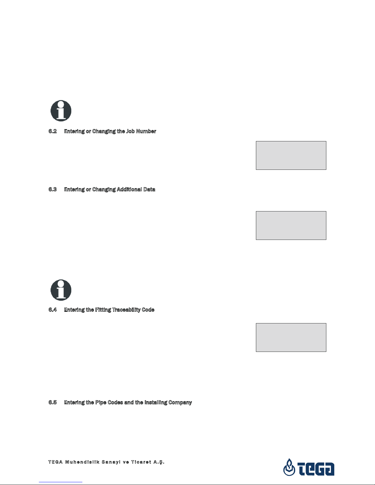
6.2 Entering or Changing the Job Number
The commission number input screen is shown by the unit before welding
or accessed by the user in the quick access screen (Display 7). It can be
entered using the alphanumeric keypad (see Info in Sect. 5.2) or by reading
it from a bar code using the scanner. The maximum length is 32 characters.
Confirm your input by pressing the START/SET key. The job number will be
saved to memory and will appear in the printed welding report.
6.3 Entering or Changing Additional Data
The additional data input screen is shown by the unit before welding, first
the screen that allows entering the first additional data, then the one for
the second additional data. This input can be entered either using the
alphanumeric keypad (see Info in Sect. 5.2) or by reading from a bar code
using the scanner.
For the first additional data input, the maximum length is 20 characters.
For the second data input, the maximum length is 15 characters. Confirm
your input by pressing START/SET. The additional data will be saved to
memory and appear in the welding report. By pressing STOP/RESET, you
skip this screen without any input.
Info
You are free to define any additional data you see fit. For instance,
you can put into these fields information on pipe length, ditch
depth, or comments that help with welded joint traceability.
6.4 Entering the Fitting Traceability Code
If this feature is enabled in the configuration menu, after the fitting code
was entered, another input “Fitting Code” is required. This is the so-called
“traceability code” or “second fitting code” of the fitting.
This input is entered either from a bar code using the scanner or manually
using the alphanumeric keypad (see Info in Sect. 5.2). Press the START/
SET key to confirm your input. If the code entered is not correct, a “Code
Error” message appears; check the string of numbers and correct as needed.
If the code entered is correct, it is saved to system memory and inserted
into the welding reports to be printed. By pressing the STOP/RESET key,
you skip this input.
6.5 Entering the Pipe Codes and the Installing Company
In the same manner as the fitting traceability code (see Sect. 6.4), enter-
ing the ISO-compliant codes of both pipes or reading them from a bar
code is possible, if this feature was enabled in the configuration (see
Sect. 10.2).
The same holds for the company installing the pipes, which can be entered,
max. 15 characters, if the option was enabled in the configuration menu.
Display 9
Display 8
Enter Job No.
********************
************
Enter Add. Data 1
********************
Display 10
*** Fitting Code ***
********************
******

4000-S
Version December 2013
12 English
TEGA Muhendislik Sanayi ve Ticaret A.Ş.
06930 Sincan Ankara,
Turkey
7 Entering Welding Parameters Manually
To be able to enter the welding parameters manually, you have first to con-
nect the fitting to the welding unit with the welding cable. Manual param-
eter input can then be accessed by pressing the ò arrow key. The screen
will show a menu as reproduced in Display 10, provided manual input is
enabled in the configuration menu (see Sect. 10.1).
Using the arrow keys ñ and ò you can select “Enter Voltage/Time” or “Enter
Fitting Code” (i.e., the ordered string of numbers that represents the fitting
code). Confirm your selection by pressing the START/SET key.
7.1 Manually Entering Welding Voltage and Time
If this option was chosen in the manual parameter input menu, a screen
appears in which the access code for manual welding parameters has to
be entered on the keypad and confirmed using the START/SET key. Then
a display like the one to the right appears on the screen. Use the alpha-
numeric keypad (see Info in Sect. 5.2) to set the welding voltage and the
welding time, according to the fitting manufacturer’s instructions, then
press the START/SET key to confirm your input. The “Start ?” message
displayed after the confirmation by START/SET indicates that the unit is
ready for welding.
Info
The access code for manual voltage and time input is disclosed
to a responsible person with the owner/operator of the welding
system and has to be requested from this person.
7.2 Entering the String of Numbers
If this option was chosen in the manual parameter input menu, the “Enter
Fitting Code” display shows. The 24 characters of the fitting code to be
entered display as asterisks ( * ). Use the alphanumeric keypad (see Info
in Sect. 5.2) to enter the code and press START/SET to confirm your input
and have it decoded. If the code entered is not correct, a “Input Error” mes-
sage appears; check the string of numbers and correct as needed. If the
code is correct, the decoded data is displayed, and the “Start ?” message
indicates that the unit is ready to start welding.
8 Downloading the Reports
Interface (see next page)
USB A Interface Port
for connecting USB mass storage media (such as a memory stick)
The interface port complies with the USB version 2.0 specification (i.e.,
maximum data rate of 480 megabits per second).
Important
Before transferring data, it is highly recommended to switch the
welding unit off and on again. If this fails to happens, there is a
risk of data transfer failure, or reports in the welding unit may
be corrupted.
8.1 Selecting the File Format
Connecting the printer or storage media causes the the screen to appear
in which the format of the output file with the welding reports can be se-
lected: a PDF file with an abstracted or extended version of the report or
the format of the welding data management application DataWork. Using
the ñ and ò arrow keys, select the file type you need and confirm your
selection by pressing the START/SET key.
Display 13
Select File Type
DataWork File
>PDF Abstract
PDF Ext'd Report
Display 12
Voltage/Time
U= 40 V t= 1000 s
Display 11
** Manual Input **
Enter Voltage/Time
>Enter Fitting Code

4000-S
Version December 2013 13
English
TEGA Muhendislik Sanayi ve Ticaret A.Ş.
06930 Sincan Ankara,
Turkey
The Service Report option is not important for normal operation. This
report lists the events related to the service and maintenance of the weld-
ing unit.
8.2 Downloading All Reports
After the file type was selected, the next screen offers a “Print All Reports”
option. Selecting it will download all welding reports currently in system
memory in the previously selected file format.
8.3 Downloading by Commission Number, Date or Report Range
After the file type was selected, the next screen offers a “By Commission
Number,” a “By Date Range,” and a “By Report Range” options. Depending
on the selection, the ñ and ò arrow keys can be used to select from the
commissions currently in system memory the desired one, of which the
reports should be downloaded, or the alphanumeric keypad can be used
(see Info in Sect. 5.2) to enter a start date and an end date, or the first and
the last report, that define a range of dates or a range of reports of which
the reports should be downloaded. When you press the START/SET key, you
cause the selected reports to be transferred to the storage media.
8.4 Understanding the Report Download Process
The download starts automatically after a selection was made among the
options. Wait for all the selected reports to transfer and the “Download
completed” message to appear on the screen.
If a problem occurs while the download is in progress, a “Printer not ready”
message shows. After the problem condition is cleared, the download re-
sumes automatically.
Info
If the welding unit recognizes a problem that cannot be cleared
while the data transfer is in progress, it does not resume the
process and displays a “Download cancelled” error message. To
acknowledge this error, press the START/SET key.
8.5 Deleting Data from Memory
The report data in memory can be deleted only after all welding reports
were transferred, which is indicated by the “Download completed” message.
When the storage media is unplugged, a “Delete Memory” message ap-
pears. If the START/SET key is pressed at this point, a further confirmation
message “Delete Memory, sure?” is shown, which has to be confirmed by
pressing the START/SET key once again. Then, the report data in memory
are deleted.
8.6 Keeping Data in Memory
When the cable or storage media is unplugged, a “Delete Memory” message
is displayed. Press the STOP/RESET key to keep the current report data in
memory. They can then be printed off once again.
Important
Make a habit of handling the internal storage as described in
Sect. 2.10, to maintain data integrity and avoid any inadvertent
deletion of the reports in memory.
9 Dedicated Welding Unit Information
9.1 Displaying Next Service and Other Characteristics of the Welding Unit
The key technical information on the welding unit itself is displayed by hold-

4000-S
Version December 2013
14 English
TEGA Muhendislik Sanayi ve Ticaret A.Ş.
06930 Sincan Ankara,
Turkey
ing the ð key down at the “Enter Fitting Code” screen. They are the software
version, the (serial) number of the unit, the date of the next scheduled
maintenance, and the number of currently available, unused reports.
If the scheduled service is overdue, a service due message appears on the
screen as soon as the unit is plugged into the mains or generator power
supply. This message has to be acknowledged by pressing START/SET.
9.2 Measuring Resistance
When the START/SET key was pressed to initiate a welding process, the
resistance value of the fitting is measured and compared to the value en-
tered as part of the read fitting code. If the gap between the two values is
smaller than the acceptable tolerance given in the code, the welding pro-
cess starts. If the gap is greater than the preset tolerance, the welding unit
aborts welding and displays a “Resistance Error” message. Furthermore, it
displays the actual resistance value measured for the connected fitting.
Prior to starting the welding process, the actual resistance of the fitting
can be measured manually from the quick access menu that can be
opened by pressing the key from the “Start?” screen (see Sect. 6.1 and
Display 4).
The reason for a resistance error may be poorly contacting and/or worn
connection terminals. Therefore, if this error occurs, check them for proper
fit and, if worn, replace them with new ones.
9.3 Overheating Switch
The welding process aborts if the temperature of the transformer in the
welding unit is too high. The overheating circuit breaker for the transformer
stops the welding if the temperature reading is too high and the remain-
ing welding time is longer than 800 seconds. The display and the welding
report will show an “Overheated” message.
9.4 Indication of Power Supply Failure at the Last Welding
The message “Power Supply Failure Last Welding” indicates that the previ-
ous welding aborted because of a power supply failure. The reason may be
too weak a generator or too long or too thin an extension cable, or a tripped
cut-out in the mounting box. The next welding operation is still possible
after acknowledging the message by pressing the STOP/RESET key.
10 Conguring the Welding Unit
With the operator identity card, the welding unit can be reconfigured. When
the MENU key is pressed, the “Enter Menu Code” message appears on the
screen. After the code was read from the card or entered manually (see
the Info in Sect. 5.2), the selection menu in Display 14 shows.
At “Settings,” the parameters related to the welding unit itself and its opera-
tion can be set. At “Recording,” the traceability data that have to or need
not be recorded and written into the reports can be enabled or disabled.
The desired sub-menu is selected using the ñ and ò arrow keys. Then to
access that sub-menu, press the MENU key.
In both parts of the configuration menu, use the ñ and ò arrow keys to
select the desired set-up option. Use the ð arrow key to toggle between
„on“ and „off“ for that set-up option.
If a “M” is shown next to a set-up option, this indicates that a sub-menu is
accessible here by pressing the MENU key.
Display 14
>Settings -M-
Recording -M-
AHST02-00-13005-06
Unit No.: 13920136
Next Service: 01-15
Avail. Rep.: 1792
4000-S
Version December 2013 15
English
TEGA Muhendislik Sanayi ve Ticaret A.Ş.
06930 Sincan Ankara,
Turkey
Press the START/SET key to confirm the set-up and save it to memory.
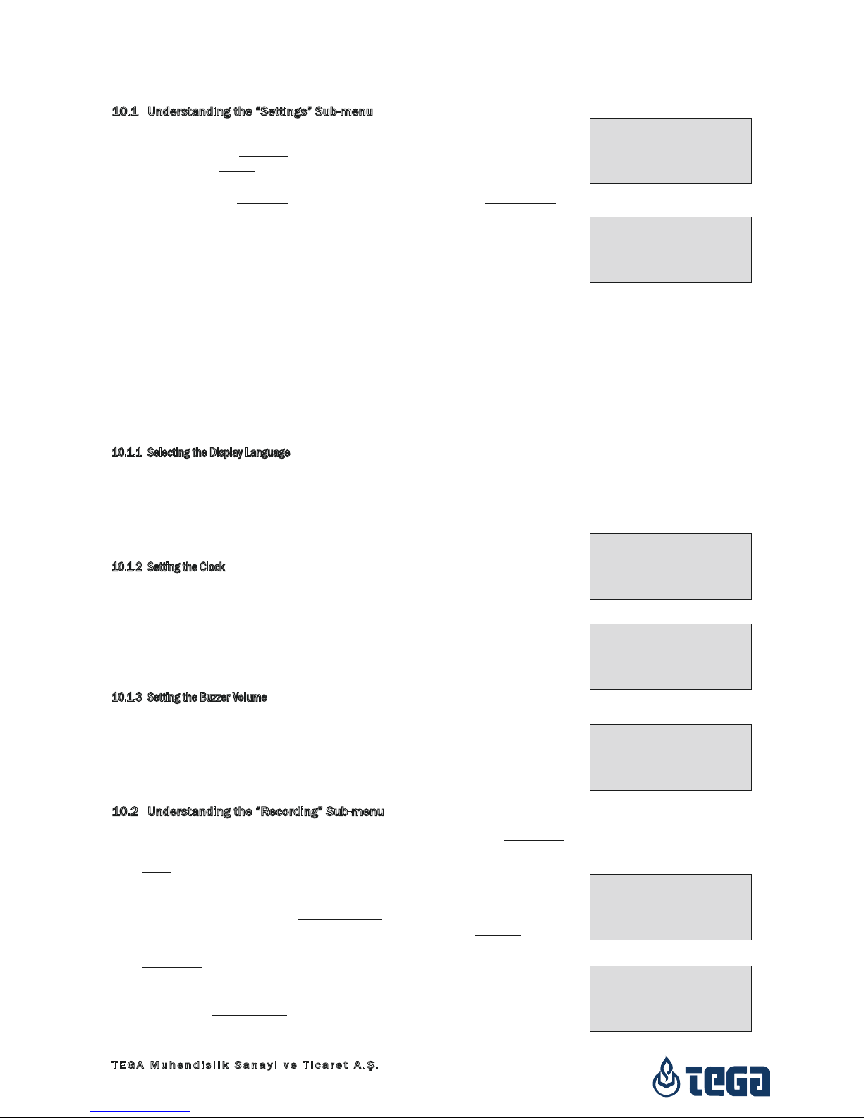
10.1 Understanding the “Settings” Sub-menu
“Memory Control on” means that when the system memory is full of reports,
the unit will be blocked until the reports are printed or downloaded,
“off,” that it works but that the oldest report will be overwritten.
“Manual Input on” means that the manual input of welding parameters
(see Sect. 7) is possible, “off,” that the manual input is not allowed.
“Language – M – ” means that by pressing the MENU key, the user can
access a sub-menu for selecting the display and report language (see
Sect. 10.1.1).
“Date/Time – M – ” means that by pressing the MENU key, the user can
access a sub-menu for setting the clock (see Sect. 10.1.2).
“Buzzer Volume – M – ” means that by pressing the MENU key, the user
can access a sub-menu for setting the volume of the status buzzer
(see Sect. 10.1.3).
“Temperature Unit – M – ” means that by pressing the MENU key, the user
can access a sub-menu for selecting centigrade or Fahrenheit as the
unit for the temperature.
“Inventory Number – M – ” means that by pressing the MENU key, the user
can access a sub-menu for entering the number under which the unit
is inventorized with the operating company.
10.1.1 Selecting the Display Language
When the “Select Language” sub-menu was selected, the screen changes
and the display reproduced in Display 17 appears.
Use the arrow keys ñ and ò to select one of the options, “Deutsch,” “Eng-
lish,” and “Français” and confirmby pressing the START/SET key.
10.1.2 Setting the Clock
When the “Set Clock” sub-menu was selected, the screen changes and the
display reproduced in Display 18 appears.
The time of day and the date can be set using the keypad. The portions
“Hour,” “Minute,” “Day,” “Month,” and “Year” are set separately. Press the
START/SET key to confirm your settings.
10.1.3 Setting the Buzzer Volume
When the “Set Volume” sub-menu was selected, the screen changes and
the display reproduced in Display 19 appears. The buzzer can also be
heard. Turn the buzzer volume up or down to the desired value using the
, ð arrow keys (from 0 to 100) and confirm your setting by pressing the
START/SET key.
10.2 Understanding the “Recording” Sub-menu
“Welder Code on” means that the welder identification code has to be
entered as set with “Welder Code Options,” “off,” that this is impos-
sible.
“Commission Number on” means that the commission number (job
number) will have to be entered or confirmed before every new weld-
ing, “off” that the user is not prompted to enter it.
“Additional Data on” means that the additional data will have to be en-
tered or confirmed before every new welding, “off” that the user is not
prompted to enter them.
“Fitting Code on” means that the second, so-called traceability code of
the electrofusion fitting has to be entered before every welding, “off,”
that this is not possible.
“Pipe Codes on” means that the codes of both pipes/components to be
Display 15
Display 16
Display 20
Display 21
Settings
>Memory Control off
Manual Input on
Language -M-
*** SET-UP MENU ***
Date/Time -M-
>Buzzer Volume -M-
Temp. Unit -M-
Data Recording
Welder Code on
>Commission No. off
Additional Data on
Data Recording
>Fitting Code on
Pipe Codes off
Installing Comp.off
Display 18
Display 19
**** LANGUAGE ****
>Deutsch
English
Francais
BUZZER VOLUME
< ------50-------- >
Display 17
Date/Time
21.06.13 14.28

4000-S
Version December 2013
16 English
TEGA Muhendislik Sanayi ve Ticaret A.Ş.
06930 Sincan Ankara,
Turkey
jointed have to be entered before every welding, “off,” that this is not
possible.
“Installing Company on” means that the company that performs the instal-
lation work has to be entered before every welding, “off,” that this is
not possible.
Info
All data can also be read from a bar code with the scanner, pro-
vided such a bar code is available.
11 Self-Monitoring Functions Overview
11.1 Errors During Data Input
11.1.1 Code Error
An erroneous input has occurred, a code tag is poor or has an error in code
symbology or code reading was improper.
11.1.2 No Contact
There is no properly established electric contact between the welding unit
and the fitting (check push-on terminal on fitting), or the heater coil is
defective.
11.1.3 Low Voltage
The input voltage is below 175 volts. Adjust generator output voltage.
11.1.4 Overvoltage
The input voltage is over 290 volts. Decrease generator output voltage.
11.1.5 Overheated
The transformer temperature is too hot. Let the welding unit cool down for
about 1 hour.
11.1.6 System Error
CAUTION!
The welding unit has to be disconnected immediately from both the power
supply and the fitting. The auto-test has detected an error in the system.
The unit must no longer be operated and has to be sent to an approved
shop for check and repair.
11.1.7 Temperature Error
The ambient temperature measured is outside the operating range of the
welding unit, i.e., below – 20°C (– 4°F) or over + 70°C (+ 158°F).
11.1.8 Temperatur Sensor Defective
The ambient temperature sensor on the welding cable is damaged or de-
fective.
11.1.9 Clock Error
The internal system clock works improperly or is defective. Reset it, or send
the welding unit to the manufacturer for check and service.
11.1.10 Next Service
The recommended next service date for the welding unit is overdue. The
service due message has to be acknowledged by pressing the START/SET
key. Send the welding unit to the manufacturer or an approved service
point for service and check-up.
4000-S
Version December 2013 17
English
TEGA Muhendislik Sanayi ve Ticaret A.Ş.
06930 Sincan Ankara,
Turkey
11.1.11 Input Error
A code that was entered is incorrect. At manual welding parameter input,
no welding time was entered. An incorrect value was selected in the date
setting.
11.1.12 Memory Full
The system memory is full of welding reports. Print or download the reports
in memory or switch memory control off. Without memory control, a new
report overwrites the oldest existing one.
11.1.13 Downloaded Cancelled
During data transfer or printing, an error condition occurred which could
not be cleared.
11.2 Errors During Welding
All errors that occur while welding is in progress are also indicated by an
audible alarm.
11.2.1 Low Voltage
The input voltage is below 175 volts. If the error condition persists for longer
than 15 seconds, the welding process will be aborted. If the voltage goes
down below 170 volts, the welding process will abort immediately.
11.2.2 Overvoltage
The input voltage is over 290 volts. If the error condition persists for longer
than 15 seconds, the welding process will be aborted.
11.2.3 Resistance Error
The resistance value of the connected fitting is out of the read tolerance.
11.2.4 Frequency Error
The frequency of the input voltage is out of tolerance (42 Hz - 69 Hz).
11.2.5 Voltage Error
Check generator voltage and current. The output voltage does not corre-
spond to the value previously read; the welding unit has to be sent to the
manufacturer for check-up.
11.2.6 Low Current
The message is displayed if the there is a momentary current failure or if
the current decreases by more than 15% per second for 3 seconds.
11.2.7 Excess Current
The output current value is in excess; possible causes: short-circuit in the
heater coil or the welding cable. During the start stage the upper abort
threshold equals 1.18 times the value at start, in any other case the upper
limit depends on the load value and is calculated as the current at start
plus 15%.
11.2.8 Emergency Off
The welding process has been interrupted by pressing the STOP/RESET
key.
11.2.9 Heater Coil Error
The dynamic current value during welding differs by more than 15% from
the required value, indicating a short-circuit in the heater coil.
4000-S
Version December 2013
18 English
TEGA Muhendislik Sanayi ve Ticaret A.Ş.
06930 Sincan Ankara,
Turkey
11.2.10 Power Supply Failure at Last Welding
The last welding is incomplete. The welding unit was disconnected from
the power supply voltage while it was in progress. To go on using the unit,
this error has to be acknowledged by pressing the STOP/RESET key (see
also Sect. 9.4).
12 Technical Specications
Nominal Voltage 230 V
Frequency 50 Hz / 60 Hz
Power 2800 VA, 80% duty cy.
Protection Index IP 54
Primary Current 16 A
Ambient Temperature – 20°C to + 70 °C (– 4°F to + 158°F)
Output Voltage 8 V - 48 V
Max. Output Current 110 A
Memory for Welding Reports 1800 reports
Data Interface Port USB v 2.0 (480 mbit/s)
(see also the information on the data ports in Sect. 6)
Tolerances:
Temperature ± 5 %
Voltage ± 2 %
Current ± 2 %
Resistance ± 5 %
13 Service and Repair Contact
TEGA Muhendislik Sanayi ve Ticaret A.Ş.
Organize Sanayi Bölgesi Kırım Hanlığı Cad. No:1 Tel.: +90 (0)312 267 18 76
Ayaş Yolu 25. km 06930 Sincan Ankara Fax: +90 (0)312 267 18 77
Web: www.tega.com.tr Mail: tega@tega.com.tr
Info
We reserve the right to change technical specs of the product
without prior notice.
14 Accessories/Parts for the Product
Connection Terminal 4.0 threaded
Push-on Adapter 4.0 to 4.7 mm
Adapter Bag
Handheld Scanner TEGA 4000-S
Welder/Operator ID Card
Software DataWork for Windows
USB Stick

4000-S
Version Dezember 2013 3
Deutsch
TEGA Muhendislik Sanayi ve Ticaret A.Ş.
06930 Sincan Ankara,
Türkei
Inhalt
1 Einleitung ............................................................................................................................... 5
2 Sicherheitshinweise ............................................................................................................. 5
2.1 Benutzung des richtigen Fitting-Adapters......................................................................... 5
2.2 Zweckentfremdung des Schweiß- oder Netzkabels ........................................................ 5
2.3 Sicherung des Fittings und der Verbindungsstelle .......................................................... 5
2.4 Reinigung des Produkts....................................................................................................... 5
2.5 Öffnen des Gehäuses........................................................................................................... 6
2.6 Verlängerungskabel im Freien............................................................................................ 6
2.7 Kontrolle des Produkts auf Beschädigungen ................................................................... 6
2.8 Schutzkappe für Datenschnittstelle................................................................................... 6
2.9 Anschlussbedingungen........................................................................................................ 6
2.9.1 Am Netz.................................................................................................................................. 6
2.9.2 Bei Generatorbetrieb............................................................................................................ 6
2.10 Integrität des Speicherinhalts............................................................................................. 7
3 Wartung und Reparatur....................................................................................................... 7
3.1 Allgemeines........................................................................................................................... 7
3.2 Transport, Lagerung, Versand............................................................................................. 7
4 Funktionsprinzip.................................................................................................................... 7
5 Inbetriebnahme und Bedienung......................................................................................... 8
5.1 Einschalten des Schweißautomaten ................................................................................. 8
5.2 Eingabe des Schweißercodes ............................................................................................. 8
5.3 Anschließen des Fittings...................................................................................................... 9
5.4 Einlesen des Fittingcodes mit einem Handscanner........................................................ 9
5.5 Starten des Schweißvorgangs ............................................................................................ 9
5.6 Schweißprozess .................................................................................................................... 9
5.7 Ende des Schweißvorgangs...............................................................................................10
5.8 Abbruch des Schweißvorgangs.........................................................................................10
5.9 Abkühlzeit ............................................................................................................................10
5.10 Rückkehr zum Beginn der Eingabe..................................................................................10
5.11 Anzeige von Protokollen nach dem Schweißprozess....................................................10
6 Zusatzinformationen im Schweißprotokoll.....................................................................10
6.1 Eingabe von normierten und frei denierbaren Rückverfolgbarkeitsdaten ..............10
6.2 Eingabe oder Änderung der Kommissionsnummer......................................................11
6.3 Eingabe oder Änderung von Zusatzdaten.......................................................................11
6.4 Eingabe des Rückverfolgbarkeits-Formteilcodes ..........................................................11
6.5 Eingabe von Rohrcodes und Verlegerma......................................................................11
7 Manuelle Eingabe der Verschweißungsparameter........................................................12
7.1 Manuelle Eingabe von Spannung und Zeit .....................................................................12
7.2 Eingabe Zahlenfolge...........................................................................................................12
8 Ausgabe der Protokolle......................................................................................................12
8.1 Wahl des Dateiformats......................................................................................................12
8.2 Ausgabe aller Protokolle....................................................................................................13
8.3 Ausgabe von Kommissionsnummer, Datums- oder Protokollbereich........................13
8.4 Ablauf der Protokollausgabe ............................................................................................13
8.5 Löschen des Speicherinhalts ............................................................................................13
8.6 Erhalt des Speicherinhalts ................................................................................................13
9 Gerätespezische Informationen.....................................................................................13
9.1 Anzeige der Gerätekenndaten..........................................................................................13
9.2 Widerstandsmessung ........................................................................................................14
9.3 Thermischer Überlastschutz..............................................................................................14
9.4 Hinweis auf Netzunterbrechung bei der letzten Schweißung ......................................14

4000-S
Version Dezember 2013
4 Deutsch
TEGA Muhendislik Sanayi ve Ticaret A.Ş.
06930 Sincan Ankara,
Türkei
10 Konguration des Schweißautomaten............................................................................14
10.1 Erläuterungen zum Untermenü „Einstellungen“ ............................................................15
10.1.1 Wahl der Anzeige-Sprache ................................................................................................15
10.1.2 Stellen von Datum und Uhrzeit.........................................................................................15
10.1.3 Einstellen der Summerlautstärke ....................................................................................15
10.2 Erläuterungen zum Untermenü „Protokollierung“.........................................................15
11 Auistung der Überwachungsfunktionen........................................................................16
11.1 Fehlerarten während der Eingabe....................................................................................16
11.1.1 Codefehler............................................................................................................................16
11.1.2 Kein Kontakt........................................................................................................................16
11.1.3 Unterspannung....................................................................................................................16
11.1.4 Überspannung .....................................................................................................................16
11.1.5 Gerät zu heiß .......................................................................................................................16
11.1.6 Systemfehler .......................................................................................................................16
11.1.7 Temperaturfehler................................................................................................................16
11.1.8 Temperaturmessung defekt..............................................................................................16
11.1.9 Uhr defekt ............................................................................................................................16
11.1.10 Gerät zur Wartung ..............................................................................................................16
11.1.11 Eingabefehler ...................................................................................................................... 17
11.1.12 Protokollspeicher voll......................................................................................................... 17
11.1.13 Ausgabe abgebrochen ....................................................................................................... 17
11.2 Fehlerarten während des Schweißvorgangs................................................................... 17
11.2.1 Unterspannung.................................................................................................................... 17
11.2.2 Überspannung ..................................................................................................................... 17
11.2.3 Widerstandsfehler .............................................................................................................. 17
11.2.4 Frequenzfehler .................................................................................................................... 17
11.2.5 Spannungsfehler................................................................................................................. 17
11.2.6 Strom zu niedrig..................................................................................................................17
11.2.7 Strom zu hoch ..................................................................................................................... 17
11.2.8 Not-Aus ................................................................................................................................. 17
11.2.9 Windungsschluss ................................................................................................................ 17
11.2.10 Netzunterbrechung bei der letzten Schweißung............................................................18
12 Datenblatt des Produkts....................................................................................................18
13 Anschrift für Wartung und Reparatur..............................................................................18
14 Zubehör/Ersatzteile für das Produkt ...............................................................................18
Table of contents
Languages:


