Tegam 2411B User manual

MODEL 2411B
2MS/s Arbitrary Waveform Generator
Operation Manual 810029-CD
Rev. D
Publication Date: November 2005

The Tegam 2411B is a high resolution 2 MS/s Arbitrary Waveform Generator with
optional Windows® based waveform creation capability. The updated front panel
and the optional WaveWorkTM Pro +. waveform creation software make the 2411B the
easiest way to create and output the waveforms you need. The additional channels
needed for multi-phase applications can be met with a simple connection between
two or more 2411Bs. It’s combination of bench-top and system features, GPIB (option-
al) and RS232 (standard) interfaces and the integrated software which is optional and
runs under Windows make this waveform generator package a versatile tool useful to
create your waveforms for mechanical simulation, engine simulation, medical electron-
ics, modulated sine wave applications and many more applications.
Lab-quality performance
z20 commonly used waveforms front-panel selectable
zContinuous or triggered output--5 standard modes
z16-bit high-fidelity waveforms--0.005% THD (typical) at 2kHz
zHigh resolution output up to 2 MS/s
zVery large waveform memory--64k words
zLoop and link up to 100 waveforms (Sequence option)
Convenient bench-top features
zUpdated front panel includes control knob and back-lighted LCD
zCursor Control of amplitude, offset, sample clock and frequency.
zPortable, small profile package
System features
zRS-232 included
zWaveform creation software under Windows available
z4 programmable Sync pulses per waveform
TEGAM 2411B
2 MS/s Arbitrary Waveform Generator

The Front Panel
Front-Panel Entry
Press one of the System/Parameter menu keys or the Utility/Edit menu keys, and use soft keys
(F1~F4), knob or 10-keys to make selection. Then, press ENTER key.
Use the CLOCK/FREQ or AMPL/OFST key and the knob to make parameter changes. Use double
arrow key to switch parameter selection.Use arrow keys to select digits and ranges.
II
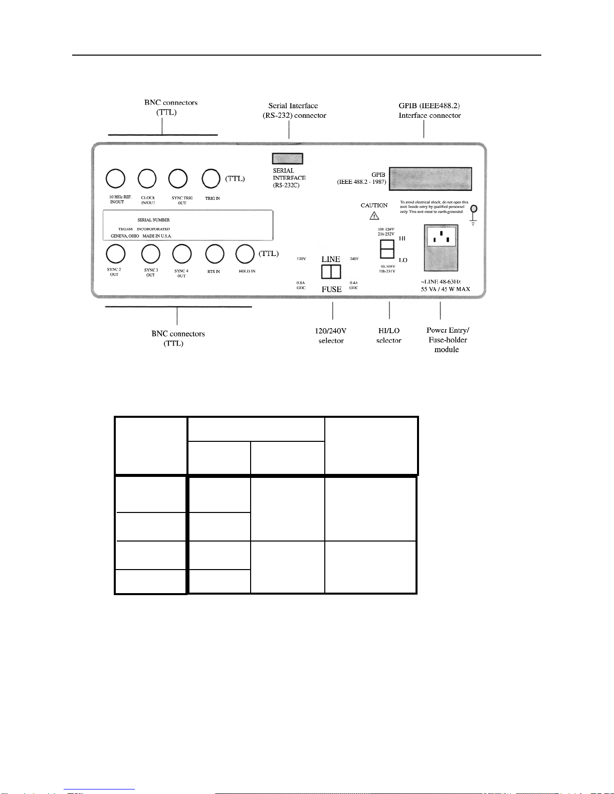
The Rear Panel
III
Mains
Voltage
Range (V)
Power Mains Setting
Hi / Lo Range Fuse Rating
Selector Selector
90 ~ 105
108 ~ 126
198 ~ 231
216 ~ 252
Lo 120V 0.8A GDC
Hi
Lo 240V 0.4A GDC
Hi

Table of Contents
The Front Panel...........................................................................................................................II
Front Panel Entry.........................................................................................................................II
The Rear Panel / Power Mains Setting......................................................................................III
Technical Specification.............................................................................................................VII
In This Manual........................................................................................................................VIII
Chapter 1 - Quick Start
To prepare the generator for use.............................................................................................1 - 2
To set the output frequency for standard waveforms.............................................................1 - 3
To set the sample clock rate....................................................................................................1 - 4
To set the output amplitude.....................................................................................................1 - 5
To set the output offset voltage...............................................................................................1 - 6
To select a standard waveform...............................................................................................1 - 7
To change the default length of standard waveform..............................................................1 - 8
To select a user-defined waveform.........................................................................................1 - 9
To select a sequence waveform (option)...............................................................................1-10
To select operating mode.......................................................................................................1-12
Chapter 2 - About Arbitrary Waveforms
Waveform Generation.............................................................................................................2 - 2
Waveform Cycle..................................................................................................................... 2 -2
More on Waveform Cycle...................................................................................................... 2 -3
Digital and Analog Scaling.....................................................................................................2-3
Other Considerations...............................................................................................................2- 3
Examples-Digital and Analog Scaling....................................................................................2- 4
Waveform Types.....................................................................................................................2- 5
Sync Pulse...............................................................................................................................2- 6
Sync Outputs...........................................................................................................................2- 7
2411B Block Diagram.............................................................................................................2 - 8
Chapter 3 - Front-Panel Menu Operation
Parameter Control
MODE menu............................................................................................................3 - 2
Sample Clock and Frequency (SCLK/FREQ) menu...............................................3 - 2
Amplitude/Offset (AMPL/OFST) menu..................................................................3 - 2
Function (FUNC) menu............................................................................................3 - 3
OUTPUT menu........................................................................................................3 - 4
Waveform Setup.....................................................................................................................3 - 4
Waveform Edit.................................................................................................................... ...3 - 4
System Control........................................................................................................................3 - 5
Default Settings.......................................................................................................................3 - 6
Standard Waveform List.........................................................................................................3-9
Chapter 4 - Waveform Creation System
Components............................................................................................................................4 - 2
User Interface.........................................................................................................................4 - 2
Memory Organization
Introduction..............................................................................................................4 - 4
Default Partitioning.................................................................................................4 - 4
Waveform Numbering..............................................................................................4 - 4
Changing Waveform Block Length.........................................................................4 - 4
Waveform Number Block Length............................................................................4 - 5
Deleting Waveform..................................................................................................4 - 5
Inserting New Waveform numbers..........................................................................4 - 5
IV

Table of Contents
Waveform Creation Using Front Panel
Introduction...............................................................................................................4 - 6
Line Mode................................................................................................................4 - 6
Vertex Mode............................................................................................................ 4 - 9
Math Operation........................................................................................................4-13
Examples.................................................................................................................4-14
Sequence Generator (Option)
Introduction...............................................................................................................4-17
Programming a Sequence.........................................................................................4 -17
Deleting a Sequence.................................................................................................4-18
Adding a Step into an Existing Sequence................................................................4-18
Deleting a Step from an Existing Sequence.............................................................4-19
Modyfying a Step within an Existing Sequence......................................................4-19
WaveWorks Pro Software (Option)........................................................................................4-20
Chapter 5 - Multi-Instrument Operation
Basic Connection.....................................................................................................................5- 2
Multiple Phase Connection......................................................................................................5- 3
Multiple Phase Operation........................................................................................................5- 4
Multiple Phase Setup...............................................................................................................5-6
Chapter 6 - Performance Verification
Introduction..............................................................................................................................6-2
Test Equipment Required.........................................................................................................6- 2
Verification Test.......................................................................................................................6- 2
Verification Test Sheet.............................................................................................................6-4
Chapter 7 - Remote Interface Operation
Introduction..............................................................................................................................7-2
To set the GPIB address..........................................................................................................7-2
To set the RS-232 parameters..................................................................................................7- 3
RS-232 Adapter Cables...........................................................................................................7- 4
Before sending commands......................................................................................................7- 5
Command Features
Command Execution.................................................................................................7- 5
Waveform Selection..................................................................................................7-6
Waveform Deletion...................................................................................................7- 6
Command Set..........................................................................................................................7- 7
Reset and Default Values...................................................................................................... 7-14
RS-232 Programming Example.............................................................................................7-16
GPIB Programming Example................................................................................................7-18
Chapter 8 - Advanced Remote Operation
RS-232 Overview
Introduction...............................................................................................................8- 2
Interface Requirements.............................................................................................8-2
Verifcation of Communication..................................................................................8-3
Command Syntax......................................................................................................8-3
Common Commands.................................................................................................8- 3
Event Register and Status and Error Reporting........................................................8-4
Functional Syntax Elements......................................................................................8- 4
V

Table of Contents
GPIB (optional) (IEEE-488.2) Overview
Introduction................................................................................................................8-7
Common Commands.................................................................................................8-8
Status and Event Registers........................................................................................8-9
Functional Elements - Syntax and Nomenclature...................................................8-11
Error Reporting........................................................................................................8-12
Data Formats
Decimal Numeric Program Data..............................................................................8 -13
Arbitrary Block Program Data.................................................................................8 -14
Remote Command Set
Introduction..............................................................................................................8-15
Command Sequence..................................................................................................8-15
Command Execution................................................................................................8-15
Command Set Hierarchy...........................................................................................8-16
Stacked Queries........................................................................................................8-16
Command Set............................................................................................................8-17
Waveform Editing Principles..................................................................................................8-19
Waveform Memory Format
Decimal Waveform Download.................................................................................8-21
Binary Waveform Download....................................................................................8-22
Example....................................................................................................................8-23
Binary Download Test Program for GPIB...............................................................8-25
Arbitrary Sync Pattern Programming
Overview.................................................................................................................. 8-28
Start/Length Sync Programming..............................................................................8-28
Block Sync Programming.........................................................................................8-29
Combined Waveform and Sync Programming.........................................................8-30
Single Point Sync Query...........................................................................................8-31
Multiple Point Sync Query.......................................................................................8-31
Sequence Generator Operation (Option)
Add Sequence...........................................................................................................8-33
Auto Sequence..........................................................................................................8-33
Sequence...................................................................................................................8-33
Sequence Burst.........................................................................................................8-34
Sequence Burst Number...........................................................................................8-34
Appendix
Menu Logic Tree
Standard Waveshape Equations
Amplitude/Offset Graph
Index
Warranty
VI

Techical Data Sheet
TEGAM 2411B 2MS/s Arbitrary Waveform Generator
VII
Output Waveforms
Up to 100 High-Definition User-defined Waveforms,
Standard Waveforms: Sine, Square, Triangle, ±Sawtooth,
DC, ±Pulse, ±Exponential, AM, SCM, FM, Lin/Log
Sweep, Sin x/x (Sine), Gaussian, Haversine, Circle,
Noise.
4 programmable sync pulses per waveform.
Sequence Generator (Optional)
Waveform: Transient-free Loop and Link
Repetitions: Loop:1,048,575 times Link:100 waveforms
Program: 1000 Steps total
File: 100 Sequences
Waveform
Storage: 100 waveforms
Resolution:
Horizontal Points: 65,504 max., 16 min.
Vertical Points: 16 bits, 65,536 (-32768 to +32767)
Sample Rate:
Range: 0.1 Hz to 2MHz (10s to 500ns)
Resolution: 4 digits
Accuracy:±50ppm
Transition Time: <150ns
(Tested with square wave, filter off, 10Vp-p, 50Ω
termination.)
THD + Noise: -86dB typical (2kHz sinewave)
(Tested with 80kHz measurement bandwidth, 2 MHz
clock, sinewave, 1000 points, filter on. full amplitude, 50Ω
termination.)
Amplitude and Offset
Range Resolution Accuracy
±1.00 to 10V 10mV 1 % of setting + 20mV
±100mV to 999mV 1mV 3% of setting + 5mV
±10mV to 99.9mV 100mV 5% of setting + 1mV
(Tested with 1kHz sinewave plus DC offset, 50
Ω
source
impedance, open circuit.)
Selectable Analog Filter
Cutoff: 700kHz, 7th order; 40kHz, 3rd order
Operational Modes
Continuous: Output runs continuously between selected
memory address locations.
Triggered: Output at start point until triggered, then runs
once.
Gated: As triggered except output is continuous until gate
signal ends.
Burst: Each trigger outputs a preprogrammed number of
waveforms from 1 to 1,048,575.
Toggled: Alternate triggers gate the output waveform.
Master-Slave: For multi-unit operation.
Cont-Sync: multiple units run continuously in sync with
the master unit
Trig-Sync: multiple units run in sync with the master unit
for one cycle when the master unit is triggered.
Trig-Sequence: a tail-chasing mode between the master
and the slave unit initiated by triggering the master unit.
Outputs
Output: Front-panel main waveform output, 50Ω
impedance.
Sync Outputs: Front-panel TTL sync output, 50Ω
impedance plus 3 rear-panel TTL outputs.
Programmable.
Clock Out: Rear-panel AWG waveform sample clock
output (TTL). x2 sample clock.
Reference Out: Rear-panel internal 10MHz reference
output (TTL).
Sync Trigger Out: Triggers additional units
Inputs
Trigger Input: Rear-panel TTL trigger input for trig-
gered,gated, burst, toggled and master-slave modes.
External TTL Sample Clock Input:< 4MHz
Reference In: Rear-panel 10MHz reference input will
phase lock the internal crystal-controlled oscillator.
Trigger Sources
External Trigger Input
Manual Trigger
Waveform Creation Tools (Option)
Software: WaveWorks Pro+ for Windows
Operating System: Windows 2000, 98 or 95.
PC Requirements: 486DX or better with 4MB RAM
space
Interface: COM port or National Instrument AT-GPIB
card (or equivalent)
Standard Function: 30
Math Operation:
Operators: 13
Transfer Functions: 20
Sequence Creation (optional hardware required)
Waveform Analysis:
Frequency Domain: FFT and IFFT: up to 500th
harmonic, graphic display and
tabulation
Time Domain: Waveform and Digital Pattern
Edit: Point, Vertex and Harmonics (FFT, IFFT).
Computer Interface
RS-232C: 19.2kBaud. max.
GPIB (optional): IEEE Std. 488.2-1987
General
Stored Settings: 31
Temperature Range: +23 °C ± 3°C for specified oper-
ation. Operates 0°C to +50°C. Storage -20°C to +60°C.
Dimensions: 11.5cm (4.53 in.) H; 25.8cm (10.14 in.)
W; 30cm (11.81 in.)D.
Weight: 5.0kg (11 Ibs)
Power: 55VA; 45W (max) 100/120/220/240 VAC. +5%,
-10%; 48 to 63 Hz.
Weight and dimensions are approximate. Errors and omissions except-
ed. Prices and specifications subject to change without notice. TEGAM
is the registered trademark of TEGAM, Inc.
© Copyright 2000 TEGAM Inc. All rights reserved.

Quick Start: Chapter 1 will prepare you to use the basic parameters of the arbitrary waveform generator
within a short time.
About Arbitrary Waveforms: Chapter 2 provides you the basic concept of arbitrary waveform genera-
tion.
Front-Panel Menu Operation: Chapter 3 describes the front-panel menu operation.
Waveform Creation System: Chapter 4 describes the overview of waveform creation system.
Multi-Instrument Operation: Chapter 5 describes the basic connection and the multiple unit operation
for multiphase applications. You will leam about the hardware connections and the available master-
slave mode.
Performance Verification: Chapter 6 describes the procedure to verify the2411B specification.
Remote Interface Operation: Chapter 7 describes the remote interfaces. You will leam how to send
simple commands over RS-232 or GPIB. The detail command list is included in this chapter.
Advanced Remote Operation: Chapter 8 describes in details the remote interfaces. It is intended for
use by experienced systems programmers to control every feature of the 2411B from both RS-232 and
GPIB.
In this manual
VIII

1
Quick Start

Chapter 1 Quick Start
To prepare the generator for use
To prepare the generator for use
The following steps will help you verify that the generator is ready for use.
1. Check the list of supplied items.
Verify that you have received the following items with your arbitrary waveform generator.
• One power cord
• One serial interface cable
• The instrument operation manual on CD ROM.
2. Check the power mains voltage setting on the rear-panel.
Verify that the mains voltage is set to the range for your location. You can verify the setting by observ-
ing the position of the slide switches on the rear panel. Refer to the rear panel diagram on page III.
3. Connect the power cord and turn on the generator.
The generator power switch is located at the lower left corner of the front-panel. The front-panel display
will light up and indicate the name, the model number and the firmware version release level.
4. Press OUTPUT button, select ON (F1 softkey) and then press ENTER.
The LED above OUTPUT connector turns on. Now, the generator output is on.
5. Connect a BNC cable from the OUTPUT connector to an oscilloscope input.
Terminate the cable at the oscilloscope input with 50Ω load.
6. Connect a BNC cable from the front panel SYNC OUT connector to the external sync input of
the oscilloscope.
Make an adjustment to the oscilloscope to synchronize the output waveform on the display.
1-2
Chapter 1 Quick Start
To set the output frequency for standard waveforms
To set the output frequency for standard waveforms.
At the initial power-on, the generator output is turned off. Be sure to follow the step 4 of the page 1-2 if
you have not yet turned on the generator output. The following steps will show you how to change the
output frequency to 12kHz. Remember that the output frequency is computed as shown.
Waveform Frequency = [(Sample Clock) / (Waveform Length)]*(Number of Cycles in the Waveform Frame)
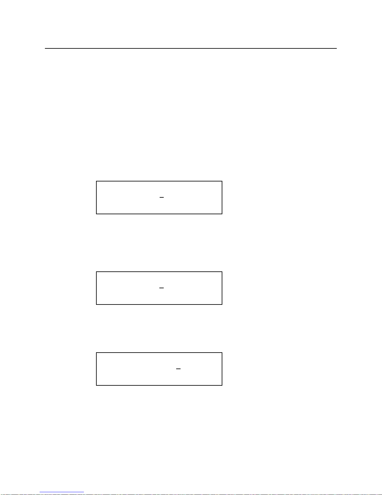
1. Press SCLK (Sample Clock) / FREQ (Frequency) button. Then, press double arrow button to
exchange the parameters.
The displayed frequency is either the power-on value or the previously selected
2. Enter the magnitude of the desired frequency.
Use the right-arrow button to place the cursor under the selected digit. Turn the knob to set the digit to
2. The frequency will indicate 12.00 kHz.
3. Select the desired frequency range.
Use the right-arrow button to place the cursor under the multiplier (k). Turn the knob counterclockwise
to switch the range by a decade.
1-3
FREQ= 10.00 kHZ
SCLK= 10.00 MHz
FREQ= 12.00 kHZ
SCLK= 12.00 MHz
FREQ= 1.200 kHZ
SCLK= 1.200 MHz

Chapter 1 Quick Start
To set the sample clock rate
To set the sample clock rate.
At the initial power-on, the generator outputs a free-running sine wave at 10kHz with an amplitude of
5.0 V peak-to-peak (into 50Ωtermination) after the output is turned on. The following steps will show
you how to change the sample clock rate of a user-defined waveform or an optional sequence. The out-
put frequency of any waveform is:
Waveform Frequency = [(Sample Clock) / (Waveform Length)]*(Number of Cycles in the Waveform Frame)
1. Press FUNC (function) key and select a user-defined waveform, WAV#. Select WAV#0 and press
ENTER.
The default length of a user-defined waveform is 2000 points.
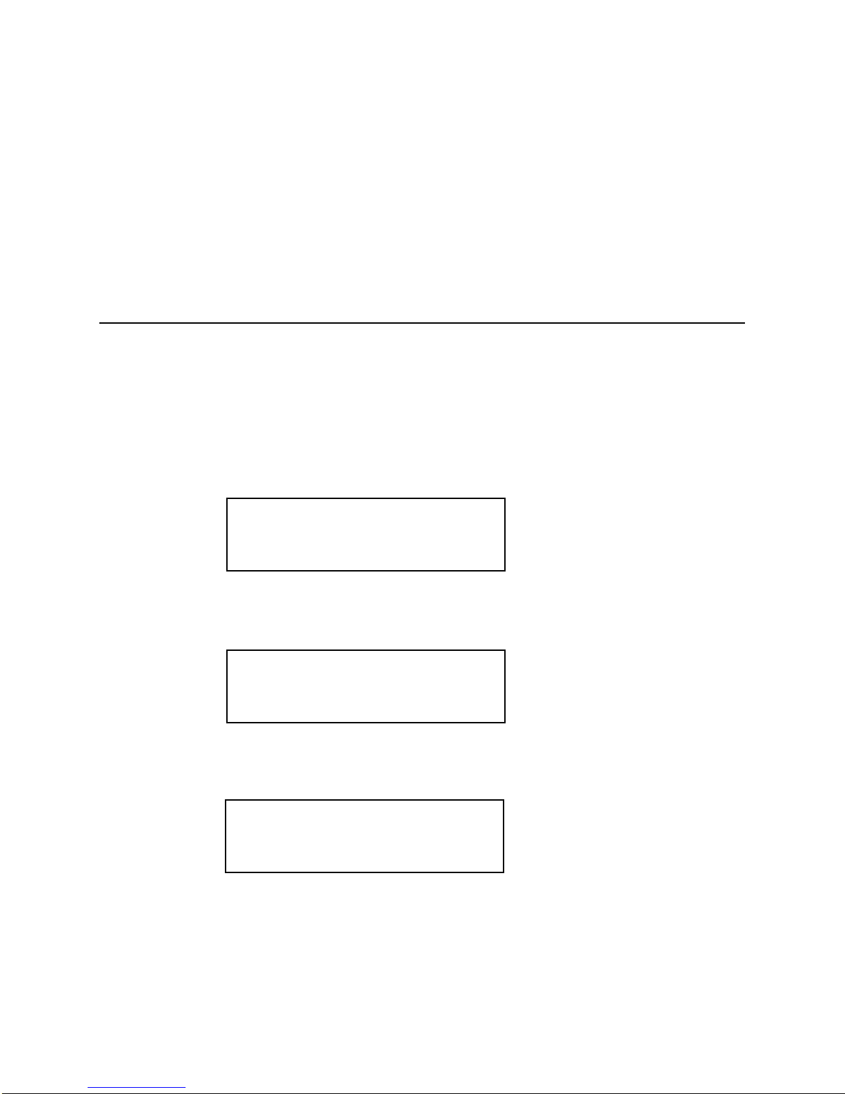
2. Press SCLK/FREQ (Sample Clock/Frequency) button.
The displayed sample clock is either the power-on value or the previous sample clock rate selected.
3. Enter the magnitude of the desired sample clock rate.
Use the right-arrow button to place the cursor under the selected digit. Turn the knob to set the digit to
2.
4. Select the range of the desired frequency.
Use the right-arrow button to place the cursor under the multiplier (M). Turn the knob counterclockwise
to switch the range by a decade. Observe the output frequency has changed by a decade.
1-4
SCLK= 10.00 MHZ
FREQ= 5.000 kHz
SCLK= 12.00 MHZ
FREQ= 6.000 kHz
SCLK= 1.200 MHZ
FREQ= 600.0 Hz

Chapter 1 Quick Start
To set the output amplitude
To set the output amplitude
At the initial power-on, the generator outputs a cw sine wave at 10 kHz with an amplitude of 5V peak-
to-peak (into 50Ωtermination) after the output is turned on. The following steps will show you how to
change the amplitude to 2.5V peak-to-peak.
1. Press AMPL/OFST (Amplitude/Offset) button.
The displayed amplitude is either the power-on value or the previous amplitude selected.
2. Select the digit you are going to modify.
Use the left-arrow button to place the cursor under the selected digit.
3. Enter the magnitude of the desired amplitude
Turn the knob counter clockwise to set the digit to 2.
4. Enter the magnitude of the desired amplitude.
Use the right-arrow button to place the cursor under the selected digit. Turn the knob to set the digit to 5
to change the magnitude.
1-5
AMPL= 5.000 V
OFST= 0.000 V
AMPL= 5.000 V
OFST= 0.000 V
AMPL= 2.000 V
OFST= 0.000 V
AMPL= 2.500 V
OFST= 0.000 V

Chapter 1 Quick Start
To set the output offset voltage
To set the output offset voltage.
At the initial power-on, the generator outputs a cw sine wave at 1 kHz with an offset voltage of 0 V
(into 50Ωtermination) after the output is turned on. The following steps will show you how to add 1.0
V offset to the output.
1. Press AMPL/OFST button twice or press the double arrow button to exchange the
parameters.
2. Select the digit and enter the desired offset voltage.
Use the left-arrow button to place the cursor under the number 0. Turn the knob to select the desired off-
set voltage. You must observe some restrictions for the magnitude of the offset voltage. The sum of the
offset and peak amplitude can not exceed ±5 volts when terminated with 50Ω.
1-6
OFST= 0.000 V
AMPL= 2.500 V
OFST = 1.000 V
AMPL = 2.500 V
Amplitude and DC Offset Ranges
TEGAM 2411B utilizes unique combinations of the input and output
attenuators for the output amplifier in order to accomplish the optimized
signal attenuation. Therefore, if DC offset is applied to the signal, the
following restrictions must be observed.
Amplitude Range Legal Amplitude+DC Offset Limits
1V ~ 10.2V Amplitude + | DC Offset | < 10.4V
100mV ~ 999mV Amplitude + | DC Offset | < 1.00V
10mV ~ 99mV Amplitude + | DC Offset | < 100mV

Chapter 1 Quick Start
To select a standard waveform
To select a standard waveform.
At the initial power-on, the generator outputs a free-running sinewave at 1 kHz after the output is turned
on. The following steps will show you how to select another standard waveform.
1. Press FUNC (function) button.
Select standard waveforms by pressing STDW (standard wave). The default length is set to 1000 points.
2. Use the right and left arrow buttons to view the selection menu.
Select one of the 20 standard waveforms.
3. Press SIN (sinewave) button to select parameter(s).
Use the double arrow button to exchange the parameters. Press the waveform button again to select
more parameters if available.
4. Turn the knob or key in the parameters on the 10-key to enter parameters.
1-7
FUNC:
wav# seq# STDW view
FUNC:STDW:
SIN squ tri saw+
FUNC:STDW:
am scm fm hsin
N=1.00 P=0.000
SIN squ tri saw+
Chapter 1 Quick Start
To change the default length of standard waveform
To select a standard waveform (continued)
5. Press ENTER button to set parameters.
Note: the standard waveform data is recomputed after the parameters are changed. It may take a frac-
tion of a second to several seconds to compute and draw the new waveshape. The time to draw the
waveform depends on the sample length and type of waveform selected.
To Change the default length of standard waveform.
The default length of 1000 points will create the maximum frequency of 2kHz sinewave. If higher fre-
quency is required, the default length must be changed. The minimum length is 16 points.
1. Press SETUP button.
2. Press STDW (F2 soft key).
The display indicates standard waveform is located at the memory address of 10000 and the length is
1000. The 2411B automatically select the waveform memory location.
3. Press LEN (F4 soft key).
4. Turn the knob or key in the length on the 10-key to enter new length. Then, press OK (F3 soft
key).
1-8
SETUP:
WAV# STDW SEQ#
01000@10000 STDW
SYNC LEN
free=54504 L=1000
OK CANC

Chapter 1 Quick Start
To select a user-defined waveform
To select a user-defined waveform.
At the initial power-on with the factory setting, the generator outputs free-running sinewave at 10 kHz
after the output is turned on. The following steps will show you how to select a user-defined arbitrary
arbitrary waveform. All user-defined waveforms must be created on the PC and downloaded to the
2411B using WaveWorks Pro or other software, or created using the edit utility prior to the selection.
However, we have loaded the first five user-defined waveform locations with sample waveforms for
your verification.
1. Press FUNC (function) button.
2. Press WAV# (F1 soft key).
If the waveform does not contain any data, it will not be displayed.
3. Press the knob to select one of the user-defined waveforms.
If the waveform does not contain any data, it will not be displayed.
4. Press ENTER button to select the user-defined waveform.
Whenever an asterisk is displayed on the LCD screen, the parameter selection is pending. You must
press ENTER button to complete the selection.
1-9
FUNC:
wav# seq# STDW view
*WAV# = 0
WAV# seq# stdw view
*WAV# = 2
WAV# seq# stdw view
WAV# = 2
WAV# seq# stdw view

Chapter 1 Quick Start
To select a sequence waveform
To select a sequence waveform. (option)
The following steps will show you how to select a sequence waveform. The sequence generator option
must be installed in the 2411B prior to proceeding with the following steps. All user-defined waveforms
must be created on the PC and downloaded to the 2411B by using WaveWorks Pro or must be created
using the internal EDIT function before making the sequence selection. However, we have pre-loaded
the first five user-defined waveforms with the sample waveforms. We will utilize these waveforms to
demonstrate the sample sequence.
1. Press FUNC (function) button.
2. Press SEQ# (F2 soft key).
Turn the knob to select the desired Sequence waveform number. Press ENTER button. You will be able
to view the sequence waveform, unless you have already altered the sequence steps.
3. Turn the knob to select one of the user-defined waveforms.
If the sequence does not contain any data, it will not be displayed.
1-10
FUNC:
wav# seq# STDW view
*SEQ# = 0
wav# SEQ# stdw view
*SEQ# = 2
wav# SEQ# stdw view

Chapter 1 Quick Start
To select a sequence waveform
To select a sequence waveform (continued)
4. Press ENTER button to select the sequence waveform.
Whenever an asterisk is displayed on the LCD screen, the parameter selection is pending. You must
press ENTER button to complete the selection.
Note: Each SEQ# may contain up to 4096 steps, use up to 1000 user-defined waveforms which may be
repeated up to 1,000,000 repetitions.
1-11
SEQ# = 2
wav# SEQ# stdw view
Table of contents
Other Tegam Portable Generator manuals

Popular Portable Generator manuals by other brands

IHS
IHS Roof Pro 12000 Operator's manual

Winco
Winco W70PTOS Installation & operator's manual

Stanley
Stanley FATMAX FMXGN4400022 Owner's operating manual

Tektronix
Tektronix AWG 2021 brochure

Peak Scientific
Peak Scientific Precision Series user manual

Festo
Festo VABF-S4-CB-VH Series Instructions & Operating


