Festo VABF-S4-CB-VH Series Parts list manual

8099796
VABF-S4-...-CB-VH/VL-...
Vacuum generator
8099796
2019-05
[8099798]
Instructions| Operat-
ing

Translation of the original instructions
2 Festo — VABF-S4-...-CB-VH/VL-... — 2019-05

3Festo — VABF-S4-...-CB-VH/VL-... — 2019-05
1 About this document................................................................................................... 5
2 Safety........................................................................................................................... 5
2.1 Intended use................................................................................................................ 5
2.2 General safety instructions........................................................................................... 5
3 Product overview......................................................................................................... 6
3.1 Design........................................................................................................................... 6
3.2 Product variants........................................................................................................... 7
3.3 Display components..................................................................................................... 8
4 Function........................................................................................................................9
4.1 Function overview........................................................................................................ 9
4.2 Operating modes.......................................................................................................... 9
4.2.1 Data record mode................................................................................................... 9
4.2.2 PLC mode................................................................................................................9
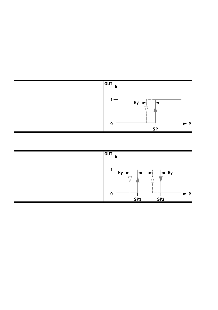
4.3 Switching functions...................................................................................................... 9
4.4 Vacuum generation...................................................................................................... 10
4.5 Control of the vacuum function..................................................................................... 10
4.6 Valve control................................................................................................................ 11
4.7 Power ejector pulse (VABF-...-AP)................................................................................. 11
4.8 Air saving function........................................................................................................ 12
4.9 Monitoring and diagnostics.......................................................................................... 13
4.9.1 Monitoring the process...........................................................................................13
4.10 Measured variables...................................................................................................... 14
4.11 Teach-in function.......................................................................................................... 14
4.12 Operating statuses of the vacuum generator................................................................ 16
4.13 Emergency-stop function.............................................................................................. 17
4.14 Error state..................................................................................................................... 17
5 Installation.................................................................................................................. 18
5.1 Pneumatic installation.................................................................................................. 18
6 Commissioning............................................................................................................ 20
6.1 Commissioning the vacuum generator......................................................................... 20
6.2 Configure ejector pulse................................................................................................. 20
7 Operation and use....................................................................................................... 21
7.1 Operating manual override........................................................................................... 21
7.2 Teach-in via FMT........................................................................................................... 23
7.2.1 Teach clock cycle.................................................................................................... 23
7.2.2 Teach-in threshold value comparator..................................................................... 24
7.2.3 Teach-in window comparator..................................................................................24
7.3 Restoring factory settings............................................................................................. 25
8 Parameter description................................................................................................. 25
8.1 Module parameters...................................................................................................... 25
Table of contents

8.2 Parameter sets.............................................................................................................. 26
8.3 Process data..................................................................................................................27
9 Maintenance and care.................................................................................................. 28
10 Malfunctions................................................................................................................ 28
10.1 Diagnostics....................................................................................................................28
10.2 Fault clearance.............................................................................................................. 29
11 Conversion and repair.................................................................................................. 30
11.1 Replace solenoid valve..................................................................................................30
12 Technical data.............................................................................................................. 30
4 Festo — VABF-S4-...-CB-VH/VL-... — 2019-05

5Festo — VABF-S4-...-CB-VH/VL-... — 2019-05
1 About this document
This document describes the use of the above-mentioned product.
All available documents for the product èwww.festo.com/pk.
2 Safety
2.1 Intended use
The vacuum generator VABF is designed for generating a vacuum. The vacuum generator is intended
exclusively for use on Festo's VTSA-F-CB valve terminal.
2.2 General safety instructions
– Only use the product in original status without unauthorised modifications.
– Only use the product if it is in perfect technical condition.
– Use the product only inside buildings.
– Take into consideration the ambient conditions at the location of use.
– Observe labelling on the product.
– Installation, commissioning, maintenance and disassembly should only be conducted by qualified
personnel.
About this document

3 Product overview
3.1 Design
1Solenoid valve VSVA
2Vacuum port
3Silencer
4Manifold sub-base for valve terminal
VTSA-F-CB (pneumatic and electric)
5Electrical interlinking to valve terminal
VTSA-F-CB
6Flow control screw for adjusting the intensity
of the ejector pulse
7Status / error LED
87-segment display
9LED switching status indication for solenoid
valve
10 Manual override for vacuum generation
11 Manual override for ejector pulse
Fig. 1 Operating elements and connections
Product overview
6 Festo — VABF-S4-...-CB-VH/VL-... — 2019-05

3.2 Product variants
Feature Value Description
Function elements VABF Vacuum generator for valve terminal VTSA-F-CB
Assignment -S4 –
Size -2 –
Product function -V2 Vacuum generator
Throttle characteristics -B1 –
Pneumatic connection -G38 G 3/8
Electrical interlinking type -CB Printed circuit board with C-bus loop-through
-VH Vacuum generator, high vacuumEquipment and equipment
-VL Vacuum generator, high suction flow rate
-14 Laval nozzle 1.4mm
-20 Laval nozzle 2.0mm
Vacuum generation
-30 Laval nozzle 3.0mm
-A Ejector pulse, electricalAdditional function
-AP Power ejector pulse, electrical
Tab. 1 Overview of variants
Product overview
7Festo — VABF-S4-...-CB-VH/VL-... — 2019-05

3.3 Display components
1LED ejector pulse (14)
2Fault LED (red)
3Status LED (yellow)
47-segment display
5LED vacuum generation (12)
Fig. 2 Display components
7-segment display
The two 7-segment displays show the current pressure value of the vacuum in kPa. When the teach
event is active, the decimal point flashes. If the air supply or evacuation time is exceeded, the com-
plete display flashes.
Operating status Display
Evacuation [Vacuum value]
Pressurise [-||-]
Teach process alternately [vacuum value] or [tE]
Tab. 2 Behaviour of the 7-segment display
Product overview
8 Festo — VABF-S4-...-CB-VH/VL-... — 2019-05

LED display
LED Meaning
Status LED
(yellow)
Off: normal operation
Flashes/illuminates: warning/error
Error LED
(red)
Off: normal operation
Illuminated: error
Tab. 3 Display of the operating status
In case of warnings or errors, additional CBUS diagnostic messages are sent è 10.1 Diagnostics.
4 Function
4.1 Function overview
The VABF is a vacuum generator with digital setpoint and actual value transmission via fieldbus. The
VABF can be parameterised via the fieldbus and send diagnostic feedback messages.
The vacuum generator is supplied with compressed air via the valve terminal.
Functions
– Configuration individual or using parameter sets è 4.2 Operating modes
– Mechanical manual override è 7.1 Operating manual override
– Monitoring of vacuum build-up through integrated pressure sensor è 8.3 Process data
– Air saving function è 4.8 Air saving function
– Diagnostic function è 4.9 Monitoring and diagnostics
– Teach function for configuration of switching points and monitoring è 4.11 Teach-in function
– VABF-...-AP only: power ejector pulse, to reduce the air flow via the vacuum generator cartridge
and silencer è 4.7 Power ejector pulse (VABF-...-AP)
4.2 Operating modes
The Operating mode parameter can be used to set the mode of operation of the vacuum generator
VABF.
4.2.1 Data record mode
In the data record mode the parameter sets for the vacuum functions are run and saved via the FMT.
Four different parameters sets can be selected via the process data.
4.2.2 PLC mode
In the PLC mode the parameters for the vacuum functions can be set individually via the process data.
The modified data are not imported until the vacuum generator is in normal position (vacuum genera-
tion and ejector pulse deactivated).
4.3 Switching functions
The binary outputs A and B can be configured via the switching functions. The switching status inform-
ation is made available as a process value.
Function
9Festo — VABF-S4-...-CB-VH/VL-... — 2019-05

The switching mode of the binary outputs A and B can be determined as threshold value or window
comparators è 7.2 Teach-in via FMT:
– Threshold value comparator: SPA2 or SPB2 = 0
– Window comparator: SPA2 or SPB2 > SPA1 or SPB1
If the air saving function is active, the binary outputs can only be configured as a threshold value com-
parator.
Threshold value comparator
Switching function:
– 1 switching point (SPA1, SPB1)
Tab. 4 Threshold value comparator
Window comparator
Switching function:
– 2 switching points (SPA1, SPB1 und SPA2,
SPB2)
Tab. 5 Window comparator
4.4 Vacuum generation
The vacuum is generated by the Venturi principle using the vacuum generator cartridges. For sizes -20
and -30, two vacuum generator cartridges are connected in parallel to generate the vacuum; for size
-14, one channel is closed with a blanking plug.
4.5 Control of the vacuum function
Vacuum generation is activated when the output signal (output bit "Vacuum generation") is present
for at least 50 ms. Since the vacuum generation is pulse-controlled, vacuum is also generated after
deactivation of the output signal.
Function
10 Festo — VABF-S4-...-CB-VH/VL-... — 2019-05

4.6 Valve control
Control of the ejector pulse
The ejector pulse is controlled via the output bit "ejector pulse". The ejection signal has a dominating
effect and stops the vacuum generation immediately. After removing the ejection signal, the valve
returns to its initial position.
If the parameter "Interlock ejector pulse" is activated and no load voltage (Uval) is present, the ejector
signal is ignored. Instead, the valve remains in the vacuum position (incl. air-saving function) or in the
normal position.
4.7 Power ejector pulse (VABF-...-AP)
So that less air escapes unused through the silencer when the vacuum generator is pressurised, the
exhaust air duct is closed with a shut-off piston during the ejection pulse. To protect the vacuum gen-
erator from dirt particles, an additional strainer is installed to filter the air sucked in.
NOTICE!
Destruction of the product due to overpressure
If the vacuum connection is tightly closed, overpressure can occur at the vacuum connection and des-
troy the pressure sensor.
• Use power ejector pulse only in open vacuum systems.
Function
11Festo — VABF-S4-...-CB-VH/VL-... — 2019-05

4.8 Air saving function
1Hysteresis
2Threshold value "Switch off suction" =
switching point SPA1
3Threshold value “Switch on suction”
4Ejector pulse
Fig. 3 Mode of operation of the air saving function
When the pressure value has reached the threshold value "Switch off suction" 2, the vacuum gener-
ation is switched off. An internal check valve prevents reduction of the vacuum. Vacuum can still be
reduced slowly due to leakage in the overall system (e.g.due to rough workpiece surfaces). To reduce
energy consumption, vacuum generation is not switched on until it falls below the lower threshold
value "Switch on suction" 3.
When transporting air-permeable workpieces, the vacuum is quickly reduced, which frequently
switches the vacuum generation on and off. In this case, a parameter set without air saving function
should be selected è 8.1 Module parameters.
If the switching frequency of the air saving function is greater than 1Hz, the air saving function is
deactivated. The vacuum generator goes into the operating status "continuous suction".
Function
12 Festo — VABF-S4-...-CB-VH/VL-... — 2019-05

4.9 Monitoring and diagnostics
The vacuum generator has monitoring functions that enable early detection of malfunctions or faults
during operation.
– Monitoring of process parameters (pressure value at vacuum connection, critical limits, evacu-
ation time tE, air supply time tB, process quality)
– Monitoring with the aid of diagnostic parameters è Tab. 15 Diagnostic parameters
– Fault detection and diagnostic messages è 10 Malfunctions
The monitoring functions are activated at the factory (except for monitoring of the evacuation and air
supply times). The monitoring of the evacuation and air supply times can be activated by setting the
critical limits evacuation time and air supply time.
4.9.1 Monitoring the process
The process quality shows information on the quality of the process with the air saving function active
è 4.8 Air saving function. The process quality is measured by calculating the vacuum decay rate (VDR
= Vacuum Drop Rate [kPa/s]) from hysteresis and leakage time (tLE). A reference variable of 50kPa/s
is applied to the VDR. A process quality of 0%corresponds to the VDR of 50kPa/s (100%= 0kPa/s).
Example 1
– Hysteresis – 5kPa = 25kPa
– Leakage time = 3s
Value Calculation Result
VDR 25kPa - 3s 8.33kPa/s
Reference to 50kPa/s (VDR) 8.33kPa/s - 50kPa/s 0.166
Process quality (1 – 0.166) x 100 83%
Tab. 6 Example 1 for calculation of the process quality
Example 2
– Hysteresis – 5kPa = 25kPa
– Leakage time = 2s
Value Calculation Result
VDR 25kPa - 2s 12.5kPa/s
Reference to 50kPa/s (VDR) 12.5kPa/s - 50kPa/s 0.25
Process quality (1 – 0.25) x 100 75%
Tab. 7 Example 2 for calculation of the process quality
Function
13Festo — VABF-S4-...-CB-VH/VL-... — 2019-05

Fig. 4 Process quality
Legend Meaning
tEEvacuation time
tLE Leakage time
tNS Post-suction time
tTrans Transport time
tBAir supply time
Tab. 8 Legend for Process quality
4.10 Measured variables
Pressure value (vacuum)
The pressure value (vacuum) between the vacuum port and filter is continuously measured. The cur-
rent pressure value is transmitted via the input data. If the operating voltage of the vacuum generator
is switched off, these values are reset.
Cycle time
A cycle covers the time from the start of evacuation through ejection to the start of the new evacu-
ation.
Evacuation time and air supply time
The evacuation time tE is measured from the beginning of the evacuation until the switching point SPA1
is reached. The air supply time tB is measured from the start of air supply to the time at which the pres-
sure value (vacuum) exceeds -5 kPa.
4.11 Teach-in function
With the teach-in function, the switching points and the monitoring functions can be configured during
operation.
Function
14 Festo — VABF-S4-...-CB-VH/VL-... — 2019-05

Teach-in threshold value comparator
With the teach-in threshold value comparator, a switching point is determined from 2 teach points.
The distance between the two teach points forms the corresponding hysteresis. The determination of
the switching point is static, which means that the measured value remains constant during the entire
teach-in process. The air-saving function is deactivated for the duration of the teach-in process.
Threshold value comparator
Teach mode:1):
– 2 teach points (TP1, TP2)
– SP2 = 0
– SP1 = 0.85 x TP2
– HY = (TP2 ½- TP1)
1) 1) TP1 = minimum pressure value, TP2 = maximum pressure value, independent of the teach sequence
Tab. 9 Threshold value comparator
Teach-in window comparator
A teach point is set for each switching point in the teach-in window comparator. In addition, a constant
hysteresis value is defined. The determination of the switching points is static. This means that the
measured value remains constant during the entire teach-in process.
Window comparator
Teach mode:1):
– 2 teach points (TP1 = SP1, TP2 = SP2)
– HY = 2kPa (adjustable)
1) 1) TP1 = minimum pressure value, TP2 = maximum pressure value, independent of the teach sequence
Tab. 10 Window comparator
Function
15Festo — VABF-S4-...-CB-VH/VL-... — 2019-05

Teach-in process times
During the teach-in process, setpoint values are calculated from a time period. The procedure is used
to determine evacuation and air supply times è Fig.5.
After starting the teach-in process, the times tE and tB are measured for each clock cycle. The times are
averaged over several clock cycles and stored as setpoint values for tE and tB. After completion of the
teach-in process, a function reserve of 100% is added to the averaged values.
Fig. 5 Dynamic teach-in mode of operation
Teach-in process quality
In the air-saving mode, one or more process cycles are run within a defined period of time between
teach start and teach stop. The leakage times tLE are measured and used to calculate the process qual-
ity è Fig.4.
In order to obtain the threshold value for the process quality warning, the process quality is addition-
ally assigned a function reserve of25%.
4.12 Operating statuses of the vacuum generator
Operating status LED 121) LED 142) Explanation
Generate vacuum Illuminated Off Solenoid coil 12: impulse con-
trol with self-latching loop
Generate vacuum Off Off Operating status after failure of
the pilot air supply or the elec-
trical supply of the vacuum gen-
erator (self-retaining)
Air saving Illuminated Illuminated Hold vacuum
Function
16 Festo — VABF-S4-...-CB-VH/VL-... — 2019-05

Operating status LED 121) LED 142) Explanation
Pressurise (ejector pulse) Off Illuminated Vacuum accelerates disas-
sembly
Normal position3) Off Off Status after the end of the
"Drop" signal
1) Vacuum generation
2) Ejector pulse
3) normal position means that the vacuum generator is not in the "Generate vacuum", "Air saving" or "Ejection" operating status.
Tab. 11 Operating statuses of the vacuum generator
If the pilot air supply or the electrical supply of the vacuum block is switched off, the respective oper-
ating status is changed as follows:
Change of state Operating status before change
of state
Operating status after change
of state
"Generate vacuum" "Generate vacuum"
"Air saving" "Generate vacuum"
"Pressurise" "Normal position"1)
Failure/deactivation of the elec-
tronics supply or the pilot air
supply of the vacuum generator
Normal position1) "Normal position"1)
"Generate vacuum" "Generate vacuum"
"Air saving" "Air saving" (vacuum is main-
tained)
"Pressurise" Function is interrupted2)
Emergency stop/switch-off of
the load voltage supply
"Normal position"1) "Normal position"1)
1) normal position means that the vacuum generator is not in the "Generate vacuum", "Air saving" or "Ejection" operating status.
2) Parameter "Interlock ejector pulse" must be active.
Tab. 12 Pneumatic and electrical state changes
4.13 Emergency-stop function
If the emergency stop (switching off the load voltage supply) is triggered during vacuum generation,
the vacuum generator remains in the vacuum generation. If the air saving function was activated, it
remains active. If the parameter "Ejector pulse locked"is activated (set to inactive at the factory), no
ejector pulse is triggered in the event of an emergency stop.
If there is a complete failure of the electrical energy (electronic supply voltage) during vacuum genera-
tion, the valve switches to the switching position "Generate vacuum".
When the power supply is switched on again, the valve remains in the "Generate vacuum" operating
status until a discharge signal is received.
4.14 Error state
If communication between the controller and the vacuum generator is interrupted, a defined status is
set. The following settings are defined in this error status state:
– Output bit "Vacuum generation" is set to 0.
Function
17Festo — VABF-S4-...-CB-VH/VL-... — 2019-05

– Output bit "ejector pulse" is set to 0.
– Parameter set is set to 0.
– Air saving function is not affected.
5 Installation
The vacuum generator is a functional element of the valve terminal VTSA-F-CB-... and assembled ex
works. Basic information on installation èOperating instructions for valve terminal VTSA-F-CB-....
5.1 Pneumatic installation
Fig. 6 Plug pattern VABF-...-A
Installation
18 Festo — VABF-S4-...-CB-VH/VL-... — 2019-05

Fig. 7 Plug pattern VABF-...-AP
VABF-S4-2-V2B1 Vacuum port
Thread size Gy
Min. internal diameter of tubing
VABF-...-VH-14 [mm] 5.5
VABF-...-VL-14 [mm] 6
VABF-...-VH-20 [mm] 6
VABF-...-VL-20 [mm] 8
VABF-...-VH-30 [mm] 9
Tab. 13 Minimum inner diameter of the connecting hoses at the vacuum connection
Installation
19Festo — VABF-S4-...-CB-VH/VL-... — 2019-05

6 Commissioning
6.1 Commissioning the vacuum generator
At initial commissioning, the vacuum generator is placed in operation with the factory settings
è Tab. 14 Default parameter sets.
The parameter Air-saving function is active in the parameter sets (è 8.2 Parameter sets) at the factory
and may have to be deactivated during initial commissioning.
Requirement
– Vacuum generator is fully mounted and connected è 5 Installation.
1. Check operating conditions and critical limits è 12 Technical data.
2. Apply operating pressure to vacuum generator via valve terminal.
3. Switch on operating voltage via valve terminal.
ÄAfter activating the solenoid 12, the valve goes into the vacuum generating position. The com-
pressed air flows through the vacuum generator and generates a corresponding vacuum at
the vacuum port. The maximum vacuum that can be generated depends on the operating
pressure. The vacuum generator is ready for operation.
Changing the operating pressure changes the power of the negative pressure at the vacuum port. This
adjusts the vacuum at the suction gripper.
Functions and parameters can be changed using the following options:
– Teach-in è 7.2 Teach-in via FMT
– Parameters using FMT è 8 Parameter description
6.2 Configure ejector pulse
Ejector pulse duration
As long as the process data value of the ejector pulse is active in the higher-level controller, an ejector
pulse is generated.
Setting the intensity of the ejector pulse
Requirement
– Vacuum generator is in operation.
1. Screw in the flow control screw completely.
2. Switch on vacuum generation.
ÄNegative pressure is generated at the vacuum port (2).
3. Switch off vacuum generation.
4. Switch on the ejector pulse via the valve terminal.
ÄNo ejector pulse is generated.
5. Switch off the ejector pulse via the valve terminal.
6. Slightly unscrew the flow control screw to regulate the ejector pulse
Commissioning
20 Festo — VABF-S4-...-CB-VH/VL-... — 2019-05
This manual suits for next models
1
Table of contents
Other Festo Portable Generator manuals
Popular Portable Generator manuals by other brands

HGI Generators
HGI Generators VRP80-TIN12-TL Operation and maintenance manual

Flash
Flash SO/PPS500W instruction manual

Matsusada Precision
Matsusada Precision RK Series instruction manual

Daewoo
Daewoo DAPD17REQ-EC user manual

Predator
Predator 59134 Owner's manual & safety instructions

Craftsman
Craftsman 580.328301 owner's manual