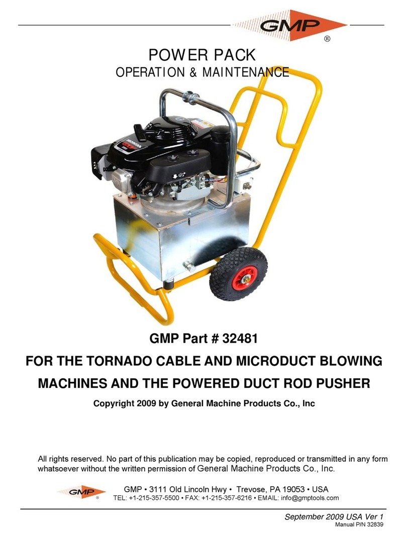
TEHMA PP700-E User guide

PP700-E/S
HIGH PRESSURE HYDRAULIC POWER PACK
TRANSLATION OF THE ORIGINAL VERSION
Rev. 3 3/2020
SAFETY MANUAL
USE AND MAINTENANCE
IMPORTANT
READ THIS MANUAL BEFORE
USING THE TOOL
KEEP ALWAYS FOR FUTURE
REFERENCES

2
CONTENTS OF THE MANUAL
Page
•INTRODUCTION 3
•SAFETY SYMBOLS 4
•PRODUCT DESCRIPTION
Description 5
Typical applications 5
Accessories 5
Sound power level 5
•TECHNICAL CHARACTERISTICS
General view –main components and their functions 6
View of the control block 7
Weight and dimension 8
Hydraulic oil 9
Flexible hose 10
Quick couplers and use 10
•SAFETY RULES 12
•PRODUCT USE
General safety instructions 12
What not to do 14
Before working 15
Start and use or the power pack 16
Cold start 16
Positioning of the power pack 16
Engine starting 16
Connection of the hoses and tool to the power pack 16
End of operations 17
•MAINTENANCE AND CARE
Maximum pressure regulation 18
Power pack cleaning 19
Periodical controls and substitution of wear out parts 20
Maintenance of the flexible hose 21
Disposal and scrapping 21
Repair 22
•PROBLEM / CAUSE / SOLUTION / CHART 23
•WARRANTY 25
•MANUFACTURER AND EUROPEAN AUTHORISED REPRESENTATIVE 25
•LABEL 26
•FAC-SIMILE EU DECLARATION OF CONFORMITY 26
PART LIST AND EXPLODED VIEW ARE ATTACHED TO THIS MANUAL IN A
SEPARATE BOOKLET.

3
INTRODUCTION
Dear customer,
Congratulations for having purchased a TEHMA product. The machine you bought, was manufactured
with high quality materials to assure your maximum satisfaction and a long-lasting service without
problems. For your safety and obtaining the best result, we recommend reading this manual and respect
the simple instructions contained, this will protect you from accidents and avoid damages to the
equipment.
Keep it always available together with its enclosures, so that it can be consulted when necessary.
IMPORTANT
SOME ENCLOSURES CONTAINING INFORMATION ABOUT ACCESSORY PARTS OR
SAFETY MANUALS OF THE MANUFACTURERS OF ELECTRIC MOTORS, ENGINES,
ALTERNATORS OF OTHER SUBCOMPONENTS OF TEHMA TOOLS, COULD HAVE BEEN
SUPPLIED TOGETHER WITH THIS MANUAL.
THESE ENCLOSURES ARE AN INTEGRAL PART OF THE MANUAL AND THEY MUST BE
KEPT TOGETHER WITH THE MANUAL ITSELF.
BE CAREFUL WHEN YOU CONNECT THE POWER PACK TO AN UNKNOWN HYDRAULIC TOOL OR
A TOOL WHICH YOU DON’T KNOW THE HYDRAULIC MAXIMUM TOLERABLE VALUES OF
PRESSURE AND FLOW OF. FOR AVOIDING ACCIDENTS AND DAMAGES TO THE EQUIPMENT, BE
SURE THAT THE MAXIMUM VALUES OF PRESSURE AND FLOW OF THE TOOLS CONNECTED TO
THE POWER PACK ARE COMPATIBLE WITH THOSE ONE OF THE POWER PACK ITSELF.
NOTE –THE TEXT AND THE ILLUSTRATIONS IN THIS MANUAL ARE AN
EXCLUSIVE PROPERTY OF TEHMA SA. THE PERSON WHO USES THE TEXT OR
REPRODUCES, EVEN PARTIALLY, ILLUSTRATIONS OR PARAGRAPHS FOR NON-
AUTHORISED PURPOSES CAN BE LEGALLY LIABLE.
DATA, ILLUSTRATIONS AND CHARACTERISTICS OF THIS MANUAL ARE ONLY
INFORMATIVE AND NOT BENDING. TEHMA SA RESERVES THE RIGHT TO MAKE
MODIFICATIONS AT ANY TIME AND WITHOUT PREVIOUS NOTICE.

4
SAFETY SYMBOLS
SAFETY SYMBOLS
This manual contains safety warnings represented by symbols indicating three different levels of
danger:
This symbol indicates an operation or situation extremely
dangerous which can cause serious accidents or death if
proper precautions are not respected
This symbol indicates a dangerous operation or situation
that can cause serious accidents or death
This symbol warns about generic danger that can cause
accidents and damages to the equipment or the properties.
This symbol indicates important information
WHEN THE EFFECTS OF A CERTAIN ACTION ARE NOT EXACTLY KNOWN, REMIND THAT
EVEN THE SIMPLEST OPERATION MAY HIDE DANGERS.
IN CASE OF DOUBTS DO NOT RISK –DO NOT MAKE EXPERIMENTS!
ASK YOUR TEHMA DEALER OR YOUR FOREMAN.

5
PRODUCT DESCRIPTION
PRODUCT DESCRIPTION
PP700 is a high-pressure hydraulic power pack that can be powered by a 2,2-kW electric motor
230V/110V (PP700-E) or by a 3,6-kW petrol engine (PP700-S).
The machine has been engineered to power high pressure tools or hydraulic cylinders, the
hydraulic pressure can reach 700 bar and can be easily reduced or adjusted by using the relief
valve integrated with the machine.
The power packs are equipped with a high-quality pump, all other hydraulic components have
been chosen to assure the best performances, robustness and a long-lasting use without
problems. The engine acceleration is manual.
TYPICAL APPLICATIONS
Powering of high-pressure hydraulic tools or equipment like:
rescue tools, lifting cylinders, railroad maintenance tools, concrete crackers, demolition tools, hydraulic
rock splitting tools and all equipment that work with pressures up to 700 bar.
ACCESSORIES
-SET OF HYDRAULIC HIGH-PRESSURE HOSES LENGTH 5 m/10 m WITH QUICK COUPLERS
-HIGH PRESSURE MALE QUICK COUPLER THREAD 3/8” NPT
-HIGH PRESSURE FEMALE QUICK COUPLER 3/8” NPT
SOUND POWER LEVEL
The sound level measured in accordance with Directive 2000/14 / EC is:
Average sound pressure dB (A): 76 (230V) / 75 (110V) / 77 (S)
Sound power level (LWA): 96 (230V) / 95 (110V) / 97 (S)
Guaranteed acoustic power (LwAG): 99 (230V) / 98 (110V) / 100 (S)
Maximum acceptable power level LwAG: 101

6
TECHNICAL CHARACTERISTICS
GENERAL VIEW –MAIN COMPONENTS AND THEIR FUNCTIONS
Fig. 1 - PP700-E/S HIGH PRESSURE HYDRAULIC POWER PACK
1 - FRAME is made in robust steel tubes with wheels, rubber feet, handles and lifting hook.
2 - MOTOR:
•ELETTRIC 2,2 KW, 230V/110V single phase 50Hz and 120V single phase 60Hz
Complete with main switch and RCBO protection
•PETROL ENGINE 3.6 kW
Complete with starter handle and ON/OFF switch
3 - COOLING SYSTEM with impeller
4 - “MAXIMUM PRESSURE” VALVE is the valve that adjust the maximum pressure limit in the unit.
5 - “CUT-OFF” VALVE releases the pressure when it is near its limit.
NOTE: The regulation screws of both valves 4-5 must be secured by the locknut to prevent from get lost
due to vibration and consequently change the pressure regulations.
The "MAX PRESSURE" and "CUT-OFF" valves have been adjusted by TEHMA to the maximum
working pressure that can be accepted by its tools.
6 - HYDRAULIC OIL TANK the oil capacity is 4 litres.
Inside the tank are located the high-pressure pumps.
7 - LIFTING HANDLE for moving the machine

7
VIEW OF THE CONTROL VALVE BLOCK
Fig. 2 THE VALVE PLATE is the group that includes all hydraulic control components, the part is
obtained working two laminated aluminium blocks.
1 - OIL FILTER for hydraulic circuit
2 - PRESSURE GAUGE is positioned in the center for reading the pressure.
3 - ON/OFF FLOW LEVER is the lever that controls the distribution valve that delivers oil to tools , the
central position in the illustration is the OFF position where the tools are still , the lever must be put in
this position before start and put off motor.
TWO POSITIONS HYDRAULIC CONTROL VALVE
The lever has two positions:
- LEFT POSITION –Pressure out from the circuit
- CENTRAL POSITION OFF –Pressure in hold/stop/neutral it is the engine starting position (see
position in the picture)
4 - QUICK COUPLING –PRESSURE LINE
5 - QUICK COUPLING –RETURN LINE

8
PP700-E/S HIGH PRESSURE POWER PACK
TECHNICAL CHARACTERISTICS
WEIGHT ( dry ) Kg 59 (E) / 57.5 (S)
HEIGHT cm 49.5
LENGTH cm 86
WIDTH cm 42.5
PRESSURE min max 210 - 700 bar
PRESSURE IS REGULATED BY TEHMA FOR ITS HYDRAULIC TOOLS
FLOW max 9 l/min
OIL TANK CAPACITY 4 liters
CONTROL VALVE TYPE 2 positions
PUMP TYPE 2 PISTON PUMPS / 1 GEAR PUMP
ENGINE CHARACTERISTICS
ENGINE CHARACTERISTICS
CHARACTERISTICS
HOSES DIMENSION THERMOPLASTIC TWIN HOSE SET - 1/4” - WORKING PRESSURE 700 BAR
LENGTH 5 m / 10 m
TERMINAL THREADS 3/8”NPT
MOTOR TYPE ELECTRIC SINGLE PHASE
230V / 110V (50Hz) - 120V (60Hz)
POWER 2,2KW
MOTOR TYPE PETROL ENGINE
POWER 3,6KW
HYDRAULIC CHARACTERISTICS
WEIGHT AND DIMENSION
STANDARD HYDRAULIC HOSES CHARACTERISTICS
MOTOR CHARACTERISTICS

9
HYDRAULIC OIL
Viscosity at the lower expected ambient temperature: max 68 cSt ( 9° E )
Viscosity at the higher expected ambient temperature: min. 22 cSt ( 3.10° E )
( cSt = centistokes ° E = Engler degrees )
HYDRAULIC OILS CORRESPONDENCE CHART
The following chart indicates the most common hydraulic oils recommended for TEHMA hydraulic tools
and power packs. The oils in the chart are suggested for standard temperatures; the left column indicates
oils for Winter operations; the right column shows the Summer ones. HYDRAULIC OILS OF OTHER
BRANDS CAN ALSO BE USED BUT THEY SHOULD HAVE EQUIVALENT CHARACTERISTICS TO
THOSE OF THIS CHART.
HYDRAULIC OIL –CORRESPONDENCE
WINTER TEMPERATURES SUMMER TEMPERATURES
AGIP ARNICA 32 ARNICA 46
BP HLP HV 32 HLP HV 46
CASTROL HYSPIN AWH 32 HYSPIN AWH 46
ELF HYDRELF DS 32 HYDRELF DS 46
ESSO INVAROL EP 32 INVAROL EP 46
MOBIL DTE 10 DTE 15
Q8 HAENDEL 32 HAENDEL 46
SHELL TELLUS T 32 TELLUS T 46
If you use the hydraulic tools in extreme climatic conditions, please contact TEHMA for more
information.
IN CERTAIN COUNTRIES OR IN SOME SPECIAL APPLICATIONS THE USE OF BIODEGRADABLE OIL IS
PRESCRIBED BY LAW, IN THIS EVENTUALITY CONTACT TEHMA FOR MORE INFORMATION.
NORMALLY THERE ARE NO PROBLEMS OF HYDRAULIC-OIL COMPATIBILITY ( MIXING DIFFERENT TYPES
OF OILS ) WHEN THE TOOL USED WAS CONNECTED BEFORE TO OTHER POWER PACKS THAT COULD
HAVE OTHER OILS, NORMALLY THERE ARE NO PROBLEMS IF THE OIL OF THESE MACHINES IS OF A GOOD
QUALITY AND REGULARLY FILTERED.
OIL FILTER AND HYDRAULIC OIL MUST BE COMPLETYELY CHANGED EVERY 250 HOURS, WHEN
CHANGING THE OIL IS BETTER CHANGE ALSO THE OIL IN THE FLEXIBLE HOSES
NEVER USE OILS CALLED ESTHERI FOSFORIC! THESE OILS ARE EXTREMELY TOSSIC AND AGGRESSIVE,
BE CAREFUL NOT TO CONNECT THE POWER PACKS TO TOOLS THAT WERE WORKING WITH THESE OILS,
MIXTURES WITH THESE OILS CAN DAMAGE THE PACK OR THE TOOLS.
THE OIL LEVEL MUST ALLWAYS BE VISIBLE FROM THE LEVEL EYE

10
FLEXIBLE HOSES
THE POWER PACK CAN BE SUPPLIED WITH A COUPLE OF HIGH PRESSURE HYDRAULIC FLEXIBLE HOSES
OF 5 M. LENGTH COMPLETE WITH QUICK COUPLERS.
THE STANDARD FLEXIBLE HOSES SUPPLIED WITH PP600-E ARE OF THE BEST QUALITY AND RATED TO
RESIST TO A PRESSURE OF 700 BAR.
THE THREAD DIMENSION IS 3/8” NPT
DO NOT USE HOSES OR COUPLERS THAT ARE NOT RATED FOR 700 BAR , IF THIS IS NOT RESPECTED
THIS NEGLIGENCE CAN RESULT IN SERIOUS ACCIDENTS AND DAMAGE TO THE EQUIPMENT
•THE FLEXIBLE HOSE ALWAYS REMAINS FULL OF OIL.
•THE FIRST TIME A NEW HOSE IS USED, IT WILL GET FULL OF OIL TAKING IT AWAY FROM THE
HYDRAULIC CIRCUIT. IT WILL BE THEN NECESSARY TO RESTORE ADEQUATELY THE OIL LEVEL IN
THE TANK.
•BE ABSOLUTELY SURE THAT IN CASE OF NEW HOSE ARE USED THEY HAVE TO BE RATED TO RESIST
AT 700 BAR
QUICK COUPLERS
THE STANDARD QUICK COUPLERS INSTALLED ON PP600-E ARE RATED TO RESISTS AT 700 BAR –
COUPLERS ARE SUPPLIED WITH PLASTIC CAPS THAT PROTECT FROM DIRT AND IMPACTS, IT IS ADVICED
TO ALLWAYS PUT THE PROTECTION ON THE COUPLERS AFTER USE.
FEMALE QUICK COUPLER MALE QUICK COUPLER
CEJN code 101151404 CEJN Code 101156404
TEHMA code A161103 TEHMA code A161104
TEHMA high pressure power packs and hydraulic tools are equipped with quick couplers made by CEJN
like those one shown in the picture.

11
USE OF THE QUICK COUPLERS
CONNECTION
•Make sure that the contact surfaces of the couplers are clean and if necessary with a rag.
•Position the male coupler towards the female one, centring them.
•While pulling back the female knurled external bush press the male coupler against the female one.
•Release the female bush and a “click” indicates that the proper connection is made.
IF A PROPER CONNECTION CANNOT BE MADE EVEN PRESSING THE COUPLERS WITH
STRENGTH, IT IS POSSIBLE THAT ONE OR BOTH COUPLERS ARE PRESSURIZED .
FOR MAKING THE CONNECTION IT WILL BE THEN NECESSARY TO TAKE AWAY PRESSURE BY
UNSCREWING THE COUPLERS FROM THEIR FITTINGS AND ALLOW SOME OIL DROPS TO COME
OUT.
DISCONNECTION
•Pull the knurled bushing of the female coupler away from the male .
•Pull the male away from female.
•The female coupler will be released and a “click” will show the disconnection.
OTHER ADVICES
•The connection/disconnection of the couplers must be done always WITHOUT OIL CIRCULATION –
WITHOUT PRESSURE.. the control valve lever must be in the OFF central position in the
connection/disconnection
•Disconnect and connect the tools from hoses and power source, just after having set the lever of the
flow control valve in OFF CENTRAL POSITION.
•The quick couplers must be dismounted from the power pack only with the engine OFF.
•If you mount or dismount the quick couplers, use only the right wrenches. If improper tools are used
the coupler hexagon can be easily spoiled.
•The quick couplers CANNOT BE REPAIRED. Discard immediately damaged or deformed couplers
and not force the connection if one coupler is damaged. In this case the damaged coupler will
immediately damage also the other good interface.
•In case of change of damaged couplers with new ones it’s important to pay attention to the Teflon seal
and to put it back rolling it on the 3/8 NPT thread before to tighten the new coupler.

12
SAFETY RULES
GENERAL SAFETY INSTRUCTIONS
MAKE SURE THAT THE TOOL OR CYLINDER YOU ARE ACTIVATING FROM THE PP700 IS RATED TO
RESIST TO A PRESSURE OF 700 Bar OR TO THE PRESSURE YOU HAVE REGULATED FROM THE PACK
THE FOLLOWING INSTRUCTIONS ARE GENERAL SAFETY RULES AND HAVE TO BE RESPECTED IN
EVERY WORKS WITH POWER PACKS AND TOOLS. WE RECOMMEND TO FOLLOW THEM CAREFULLY IN
ORDER TO AVOID ACCIDENTS AND DAMAGES TO THE EQUIPMENT AND THINGS.
•Wear ALWAYS the hard-helmet, safety goggles, gloves, safety shoes, ear protections and, when it
is prescribed, a dust musk.
•Gloves are important to be worn because if the tool is damaged the high pressure oil can be
sprinkled out from cracks of the tool with a very armful effect on skin
•Wear tight-fitting clothes and avoid operating with short trousers or t-shirts, or other bare parts of the
body. Pay attention to long loose hair, gather them to prevent they get in contact and trapped in
moving parts.
•Before operating, PREPARE ALWAYS A WORKING PLAN that considers and foresees problems,
interruptions and avoids most of all dangerous situations. This little operation strategy, guarantees
safety and improves productivity
•Place always the power pack in a plan level, in a sure and stable position protected from the traffic
and in a well visible position. Signal one’s position not to cause danger for oneself and others.
•If the power pack is transported on vehicles, be sure that it is well positioned on board and it is
blocked on the loading platform for avoiding dangerous jerks, bumps or overturning.
•Work only in good physical and mental conditions. Always pay the maximum attention!
•Do not work on unstable or adapted supports (such as oil cans, boxes, wheelbarrows, etc.). If you
need to work in elevated positions, use only stable and safe supports approved by the local safety
rules.
•When you operate in difficult positions, do not reach out and never lean against the tool. Keep the
balance on your legs.
•Be sure that the equipment is in perfect working conditions, without oil leaks.
•Keep the protection devices always in good conditions and preserve the readability of the safety
stickers.
•The working area must be examined and well-known to avoid unexpected situations. If you work
along roads, make well visible your position and warn the traffic by the use of signals, flashing lights,
or other prescribed road signs.

13
WORK ONLY IF THE ENGINES ARE OUTSIDE OR IN A WELL VENTILATED POINT. THE EXHAUST GAS OF
THE ENGINES IS ODOURLESS AND ITS INHALATION CAN CAUSE SERIOUS OR FATAL ACCIDENTS.
THE CONTACT WITH ELECTRIC ENERGIZED LINES CAN BE FATAL
•Pay the maximum attention when you cut, demolish, drill, etc. near energized electric lines that can
be buried, walled or hidden.
•Be very careful also to gas and water pipes, telephone lines or other buried cables or ducts.
•The working area must be free from objects that may fall, get spoiled, catch fire, make trip up or make
the operation difficult or dangerous.
•Warn and move away imprudent bystanders or other people not authorized or involved with the job.
•If you work in narrow or closed rooms always plan a way out that must be kept free.
•Before using the equipment make sure and prevent vehicles, machines or people from passing on the
equipment hoses or cables.
•Always connect tools to the power pack or other power sources before starting the engine.
•Keep in a safe dry place this manual and its enclosures, so they can be always available for future
consultations.
THE "MAXIMUM PRESSURE" AND "CUT-OFF" VALVES POSITIONED ON THE SIDE OF THE UNIT
HAVE BEEN ADJUSTED BY TEHMA TO THE MAXIMUM WORKING PRESSURE THAT CAN BE
ACCEPTED BY ITS TOOLS.
MODIFYING THE CALIBRATION OF THESE VALVES CAN POSE SERIOUS RISKS FOR THE
OPERATOR AND THE HYDRAULIC EQUIPMENT, THEREFORE IT IS ADVISABLE TO PROCEED
WITH THIS INTERVENTION ONLY WHEN STRICTLY NECESSARY AND AFTER HAVING
ASCERTAINED THE PRESSURE LIMITS DECLARED BY THE MANUFACTURERS OF THE TOOLS
TO BE CONNECTED TO THE UNIT.
TEHMA IS NOT RESPONSIBLE FOR ANY DAMAGES RESULTING FROM THE VARIATION OF THE
OIL PRESSURE SUPPLIED BY THE UNIT, AS WELL AS FROM THE IMPROPER USE OF THE
EQUIPMENT OR OTHER MODIFICATIONS MADE TO ITS PRODUCTS.

14
USE OF THE POWER PACK
WHAT NOT TO DO
THE FOLLOWING LIST IS GIVEN FOR DESCRIBING THE MORE COMMON ERRORS OR IMPROPER AND
DANGEROUS USE OF THE POWER PACKS.
SINCE IT IS IMPOSSIBLE TO FORESEE ANY DANGEROUS SITUATIONS, THE RULES ARE NOT SUFFICIENT
TO GUARANTEE THE TOTAL SAFETY.
IT’S RECOMMENDED TO USE ALWAYS THE MAXIMUM CAUTION IN EVERY CIRCUMSTANCES.
IN CASE OF DOUBT DO NOT RISK, BUT ASK YOUR FOREMAN.
WHAT NOT TO DO
•DO NOT USE THE POWER PACK AND THE TOOL IF THERE COULD BE THE POSSIBILITY OF GETTING
IN CONTACT WITH ENERGIZED ELECTRIC LINES OR PRESSURIZED PIPES.
•DO NOT START OR USE THE POWER PACK AND THE EQUIPMENT IN CLOSED ROOMS WITHOUT
VENTILATION , BE CAREFUL IF THERE ARE STRANGE ODOURS, THEY MAY BE DANGEROUS GASES
OR EXHALATIONS.
•DO NOT START THE POWER PACK AND ITS TOOL IF THEY ARE DAMAGED, THERE ARE OIL LEAKS OR
SOME PARTS ARE MISSING OR WRONGLY INSTALLED.
•DO NOT ALLOW THE USE OF THE EQUIPMENT TO PEOPLE THAT ARE NOT TRAINED OR WHO HAVE
NOT READ THIS MANUAL.
•DO NOT WORK IF YOU ARE NOT IN PERFECT PHYSICAL AND MENTAL CONDITIONS.
•DO NOT WORK ALONE WHEN IT IS POSSIBLE, MAKE SURE THAT SOMEBODY KNOWS WHERE YOU
ARE AND WHAT YOU ARE DOING.
•DO NOT BELIEVE IN MESSAGES OR VOICE WARNINGS GIVEN TO COLLEAGUES IN NOISY ROOMS. BE
SURE THAT THE WARNING HAS BEEN CORRECTLY UNDERSTOOD.
•DO NOT “POINT” THE TOOL AGAINST COLLEAGUES
•DO NOT STAY WITH THE FACE TOO CLOSE TO THE TOOLS
•DO NOT FILL WITH FUEL WHILE SMOKING
•DO NOT FILL WITH FUEL OR OIL WITH HOT ENGINE. DO NOT USE IMPROVISED OR DIRTY CONTAINERS
OR FUNNELS. THIS CAN CAUSE ACCIDENTS, DANGEROUS SITUATIONS AND FAILURES IN THE
EQUIPMENT.
•KEEP THE POWER PACK AWAY FROM INFLAMMABLE MATERIALS. DO NOT WORK IN ENVIRONMENTS
WITH VAPOURS AND GASES OR UNKNOWN ODOURS.
•DO NOT TRY TO REPAIR THE EQUIPMENT IF YOU ARE NOT A QUALIFIED PERSON. REPAIRS NOT WELL
DONE OR USING INAPPROPRIATE PARTS CAN CAUSE DANGEROUS SITUATIONS

15
•DO NOT CARRY OUT CONTROLS ON THE POWER PACK CHECKING OR TOUCHING WITH BARE HANDS
AND ENGINE ON. ALWAYS STOP THE ENGINE AND COOL DOWN THE EQUIPMENT BEFORE CHECKING
AND CLEANING IT
•DO NOT PULL THE FLEXIBLE HOSES OF THE POWER PACK. IF THE MACHINE SHOULD BE
REPOSITIONED USE THE PROPER HANDLES.
•DO NOT TRY TO LIFT THE POWER PACK ALONE FOR LOADING OR UNLOADING IT FROM VEHICLES.
THIS CAN CAUSE DANGERS AND ACCIDENTS
BEFORE WORKING
THE FOLLOWING INSTRUCTIONS AND CHECKS SHOULD BE CARRIED OUT EVERY TIME THE POWER
PACK IS USED AFTER A PERIOD OF INACTIVITY OF THE MACHINE OR WHEN IT IS USED BY OTHER
PEOPLE
1. CHECK THE LEVEL OF THE ENGINE OIL with cold engine and with the machine in horizontal position visualize
its level on the level indicator and fill if necessary
2. CHECK THE FUEL LEVEL be sure that the tank contains enough fuel for finishing the work, fill it if necessary
using an appropriate fuel, DO NOT FILL WITH STARTED ENGINE !
3. CHECK THE LEVEL OF THE HYDRAULIC OIL, fill with the same and compatible hydraulic oil than that one of
the tank –do not exceed the suggested level, the level should be visible from the level indicating eye. In case of
very cold temperatures, follow carefully the instructions “ starting at low temperatures “ below described
4. CHECK THAT THE TOOL USED AND THE POWER PACK HAVE COMPATIBLE HYDRAULIC
CHARACTERISTICS –IN CASE OF DOUBT DO NOT RISK but ask your TEHMA dealer or your foreman.
5. CLEAN THE POWER PACK PROPERLY if it is dirty, in particular clean the cooler eliminating mud or dirt, use
compressed air if necessary ( see chapter ” cleaning and maintenance of the equipment “ ). Check and clean
also the suction mouth of the cooler cooling air.
6. CHECK THAT ALL THE EQUIPMENT IS COMPLETE AND EFFICIENT, that there are not oil leaks and screws,
joints and plugs are well tightened.

16
START AND USE
COLD START
THE POWER PACK SHOULD BE PROTECTED FROM BAD WEATHER AND TOO HARD CLIMATES. THE
ENGINE COULD BE QUICKLY DAMAGED IF THE MACHINE IS LEFT EXPOSED TO RAIN AND LOW
TEMPERATURES WITHOUT PROTECTION. WHEN THE MACHINE IS NOT USED, IT SHOULD BE STORED IN
A DRY AND WARM PLACE REPAIRED FROM RAIN AND DAMPNESS.
IF YOU WORK IN BAD WEATHER, WHEN THE OIL CAN BE VERY HARD AND VISCOUS, IT IS VERY
IMPORTANT TO RESPECT THE FOLLOWING INSTRUCTIONS IN ORDER TO AVOID PROBLEMS OF THE
PUMP SUCKING THE OIL ( CAVITATION PHENOMENON )
1. USE HYDRAULIC OIL WITH THE RIGHT VISCOSITY ( SEE THE TABLE OF THE HYDRAULIC OILS IN
THE PREVIOUS PAGES )
2. AFTER HAVING CONNECTED THE FLEXIBLE HOSES AND THE TOOL TO THE POWER PACK ( see
following paragraph ), START THE ENGINE KEEPING IT AT THE MINIMUM FOR A FEW MINUTES TILL
THE OIL TANK WILL BE WARM WITH THE HAND CONTACT
IT IS ADVISABLE FOLLOW THIS PROCEDURE IN ALL COLD STARTS
POWER-PACK POSITIONING
1. The power pack should be placed in a flat place protected from the traffic, in well established, firm,
visible and well ventilated position.
Inflammable objects or materials should be kept away from the power pack, in particular from the
discharge side.
2. Hoses should be laid down tidily and linearly avoiding knots and tangles, also for preventing possible
stumbles.
Be sure that no vehicles or machines pass on the hoses spoiling them.
3. Do not work with the power pack left on trucks . It is better to leave the power pack on the ground. If
the power pack should work on vehicles, be sure that it is far from the lorry boards or sides, so that
both the cooling air of the engine and the exhaust gases can circulate and are properly dissolved.
IF THE HYDRAULIC OIL, LUBRICANT OR FUEL IS SPILT ON THE GROUND, FOR ANY REASON, REMOVE
THE SPILT LIQUIDS USING SAWDUST OR RAGS FOR AVOIDING ACCIDENTS AND CONTAMINATION OF
THE GROUND.
CONNECTION OF THE FLEXIBLE HOSES AND HYDRAULIC TOOL
TO THE POWER PACK
1. Lay down the flexible hoses avoiding the contact of the couplers with the mud or dirt, if possible.
2. Put the tool on the ground limiting the contact with the mud or dirt. Make sure that the tool is in
perfect condition and its accessories are efficient and well installed. Make sure that the tool control

17
valve or trigger is free and released in its OFF to avoid unwanted activation; control that the return
spring of the tool trigger is operative and efficient for avoiding an accidental starting.
3. Connect the flexible hoses to the power pack ( engine and flow control lever must be OFF)..and
to the tool
4. Start engine of power pack and allow warm up ( if this has not doe ne before )
IF A FLEXIBLE HOSE FULL OF OIL REMAINS UNDER THE SUN, THE OIL EXPANSION DUE TO THE HEAT
CAN CAUSE A PRESSURE INCREASE AND PREVENT THE CONNECTION OF THE QUICK COUPLERS. TO
DECREASE PRESSURE, LOOSEN ONE COUPLER, DRIPPING SOME OIL DROPS DE-PRESSURIZING THE
HOSE.
THE OPERATOR MUST BE FAMILIAR WITH THE EFFECT TO THE TOOL DERIVING FROM THE POSITION
OF THE CONTROL VALVE, OPERATOR MUST KNOW WHAT HAPPEN WHEN HE OPEARTES THE
CONTROL VALVE
5. Thus the hydraulic connection is completed.
Accelerate the engine as needed and use tool by operating on the pack control valve , be sure
that the action needed from the tool is definitely deriving by the position of pack control valve
END OF OPERATIONS
1. Lay down the tool avoiding and limiting contacts with the mud and dirt, if possible.
2. Put the flow lever of the power pack in OFF position, blocking the oil supply to the tool.
3. Stop the engine
4. Disconnect the tool from the flexible hose and disconnect the flexible hose from the power pack.
5. Roll up the flexible hose in circles of about 60 cm of diameter, cover the couplers with the protection
plastic caps.
6. Store the power pack when the muffler and the engine are cooled down for avoiding possible risks of
fire and accident. Store the power pack and the equipment in a safe place repaired from bumps and
atmospheric agents
7. If the power pack should be transported on trucks take care that the machine is loaded in a proper way
and blocked for avoiding tilting and harmful jerks and bumps that could damage both the power pack
and the vehicles and cause accidents.
IF DURING THE WORK FUNCTIONING OR OTHER PROBLEMS APPEAR, INDICATE THE FAILURE AND
REPAIR IT IMMEDIATELY FOR AVOIDING THE ACCIDENTAL USE OF THE DAMAGED OR FAULTY MACHINE
BY OTHER COLLEAGUES. THIS COULD CAUSE DANGEROUS SITUATIONS.

18
MAINTENANCE AND CARE OF THE POWER PACK
MAXIMUM PRESSURE REGULATION
THE "MAXIMUM PRESSURE" AND "CUT-FF" VALVES POSITIONED ON THE SIDE OF THE UNIT (SEE FIG. 2
Pag 7) PERFORM TWO DIFFERENT FUNCTIONS:
• THE "MAXIMUM PRESSURE" VALVE IS THE SAFETY VALVE THAT ADJUSTS AND CONTROLS THE
MAXIMUM PRESSURE OF THE HYDRAULIC CIRCUIT PROTECTING THE TOOLS FROM BREAKAGE OR
EXCESSIVE PERFORMANCE.
• THE "CUT-OFF" VALVE RELEASES THE PRESSURE WHEN IT IS NEAR THE MAXIMUM LIMIT, PREVENTING
THE UNIT AND THE CONNECTED TOOLS FROM OPERATING AT MAXIMUM EFFORT MORE THAN
NECESSARY.
It is very important to respect the pressure maximum value recommended for the tool.
An excessive pressure can cause breakage of the tool and equipment and can cause accidents.
Too low pressure on the tool can cause a decrease in performance and an increase in oil temperature.
The pressure gauge located on the valve top always indicates the pressure used or reached by the
tool during its use.
The "MAX PRESSURE" and "CUT-OFF" valves have been adjusted by TEHMA to the maximum
working pressure that can be accepted by its tools.
Changing the calibration of these valves can pose serious risks for the operator and the
hydraulic equipment, therefore it is advisable to proceed with this intervention only when
strictly necessary and after checking the pressure limits declared by the manufacturers of the
tools to be connected to the control unit.
IN ANY CASE THE MAXIMUM PRESSURE MUST NOT EXCEED 700 bar.
INSTRUCTIONS FOR ADJUSTING THE MAXIMUM PRESSURE
1. Turn on the unit with the lever that controls the distribution valve in the central position (OFF) without
tools or pipes connected.
2. Let the unit run for a few minutes in order to allow the oil contained in the circuit to reach the correct
operating temperature.
3. Loosen the "CUT-OFF" valve locknut (see FIG.2 page 7) and tighten the central screw until a small
pressure is applied to the bottom of the valve.
4. Turn the lever that controls the distribution valve on the channel where the quick couplings are fitted.
The pressure should rise rapidly and reach 650-700 bar.
5. Now is possible to loosen the "MAXIMUM PRESSURE" valve locknut and adjust the maximum pressure
by CAREFULLY acting on its screw.
6. Once the desired pressure has been set, retighten the "MAXIMUM PRESSURE" valve locknut.
7. Then loosen the "CUT-OFF" valve screw until it clicks and the pressure drops from the set value to 50-
100 bar.

19
8. Try rotating the central distribution lever in the central position and then again on the previous channel
to check the correct adjustment of the "CUT-OFF" valve.
NOTE: a correct calibration implies that the pressure rises rapidly from 0 to the previously set pressure
and once this limit is reached, it drops again to 50-100 bar.
9. Once the desired pressure has been set, retighten the "CUT-OFF" valve locknut.
CLEANING OF THE POWER PACK
A regular cleaning is very important for the good functioning of the equipment. A clean product will
immediately allow to find oil leaks or causes of malfunctioning. A clean tool is also more comfortable to
use and guarantees a firm grip.
CLEANING WITH HYDRO CLEANER
•The cleaning with hydro cleaner assures the best results in this type of washing. Put the power pack
on a clean surface or a wooden pallet. Be careful not to use too much the water nozzle near the tool
to avoid the removal of safety stickers and paint, in particular if hot water is used.
•A hot washing with very high pressure and with the nozzle very close to the surfaces, can cause
the removal of the paint and safety adhesives and labels
•Do not insist on the engine electric part with the nozzle –if it is necessary read on the proper
paragraph about cleaning contained in the motor manufacturer’s manual.
•After the pressure washing let the water drip from the machine also by moving it for helping the water
drain from cavities or recessed points.
•With an air gun blow all over the power pack eliminating every trace of water and moisture. Insist on
•With the machine perfectly dry, spray a protective-dewatering product (CRC-or WD40) on all
chromed parts and in the tool cavities. Spray also the area of the ON-OFF valve. For allowing the
spray to reach all points, move the movable parts.
•Dry up completely the tool handles for guaranteeing a firm grip
•Start the power pack and make it work at minimum for a few minutes
CLEANING WITH RAGS OR PAPER
•The pack can also be cleaned with a damp rag, using a brush with gasohol or an air gun for
eliminating all traces of dirt and oil
•Clean in particular the recessed points and cavities and the connection surface of the quick couplers.
•With the machine perfectly dry, spray a protective-dewatering product (CRC-or WD40) on all electric
parts, near the ON-OFF valve and in the cavities. For allowing the spray to reach all points, move the
movable parts.
•Clean and dry up completely the tool handles for guaranteeing a firm grip.

20
PERIODIC CONTROLS AND SUBSTITUTION OF WORN PARTS
•EVERY TIME THE EQUIPMENT IS USED:
1. Control the hydraulic oil level
2. Control the level of the engine oil (or make the proper maintenance as specified in the manual
of the engine manufacturer).
3. Control the condition of the hoses and quick couplers
4. Carry out a general control of the equipment.
5. Clean carefully the equipment
THE ENGINE OIL SHOULD BE COMPLETELY CHANGED AFTER THE FIRST 5 HOURS OF WORK AND THEN
AS INDICATED IN THE MOTOR MANUFACTURER’S MANUAL
•EVERY 150 HOURS OF WORK –ABOUT EVERY 3 MONTHS:
1. Carry out all the controls of the previous paragraphs.
2. Control that all screws, fastenings and fittings are perfectly locked.
3. Control the state of the hydraulic oil that should to be transparent and without foams. If
necessary, replace completely the hydraulic oil, changing also the used oil that remains inside
the flexible hoses and in the tool.
4. Carry out a complete cleaning of the equipment.
5. Check and blow the engine air filter with compressed air, if it is necessary
6. Clean the equipment carefully.
•EVERY 300 HOURS OF WORK –ABOUT EVERY SIX MONTHS:
1. Replace completely the hydraulic oil, changing also the used oil that remains inside the
flexible hoses and in the tool.
2. Replace the hydraulic oil filter cartridge.
3. Change the engine oil as specified in the manual of the engine manufacturer.
4. Replace the engine air filter.
5. Carry out all the other engine controls as specified in the manual of the engine manufacturer.
6. Check the tightening of bolts and nuts and fittings
7. Check the condition of the flexible hose and hydraulic oil cooler
8. Clean the spark plug
9. Clean the equipment carefully.
MORE ACCURATE INFORMATION ABOUT THE MAINTENANCE OF THE ENGINE ARE EQUIPPED WITH THE
MANUFACTURER’S MANUAL ENCLOSED TO THIS MANUAL.
This manual suits for next models
1
Table of contents

