―2 ―
4. PRECAUTIONS FOR INSTALLATION
3. TOOLS REQUIRED
PHILLIPS SCREWDRIVER
FLAT BLADE SCREWDRIVER
10mm,14mm SOCKET WRENCH
PLIERS
φ24mm (15/16") HOLE SAW
φ3.5mm (1/8") DRILL
VOLT METER (or CIRCUIT TESTER)
SIDE CUTTERS
SCISSORS
UTILITY KNIFE
CENTER PUNCH
CHALK
MASKING TAPE
ELECTRICAL TAPE
TRIM REMOVAL TOOL
ISOPROPYL ALCOHOL
CLEANING TOWEL
CAUTION
Please follow the Instructions for your safety.
If these Instructions are not followed. Personal injury.
Vehicle damage or degraded performance of the 110V Outlet may result.
CAUTION
Always perform installation in a building or a room.
Venlilate air to avoid exhaust gas-filled almosphere
when checking aclivalion.
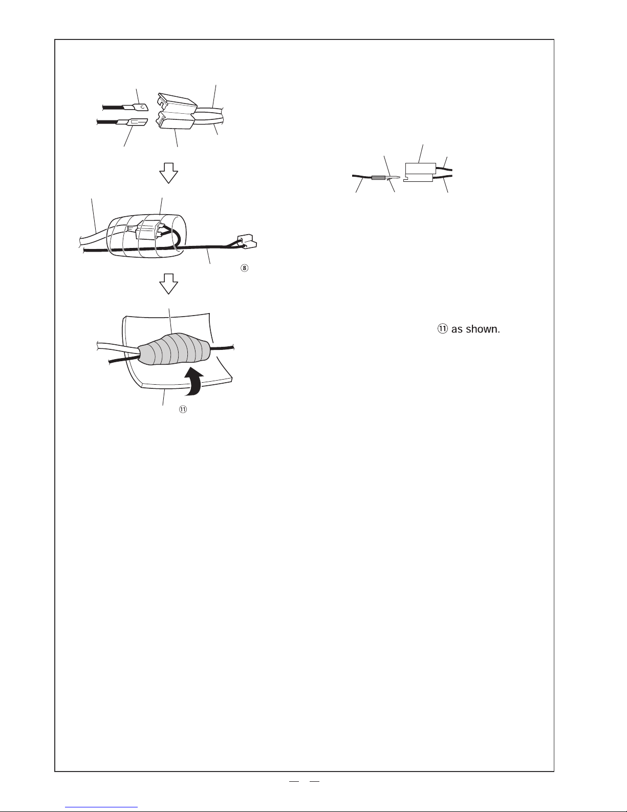
Make sure to fully ungage and connect all wire plugs &
receptacles and connectors to their individual mating
parts. Use screws or other similar fasteners to secure all
lead wire terminals in order to prevent connection failure
and/or looseness caused by vibration or oscillation.
To prevent potential damage to your vehicle during
installation, use reasonable protective covers to cover
the passenger compartment and body surface around
the engine.
Use a proper tool of correct size to tighten bolts and nuts.
Fully tighten bolts and nuts with specified tightening
torque as required. Inobservance of this instruction will
cause a potential risk of damage to bolts and nuts or.
Remove the negative battery terminal before start of
wiring work. With the battery kept connected, wiring
work will lead to a potential risk of failure or of electric
shock or inlury due to short circuit.
Do not apply an excessive force to pull off a vehicle
wire harness, to prevent loose connectors,
disconnection and/or damage.
Check that all electrical systems of your vehicle are
properly operative. Back up all memories of a radio and
other electrical systems, to avoid any possible loss
during recovery checks after installation.
When installing parts and/or removed finishers, avoid
dragging or pinching wires in order to prevent
a potential risk of accident, electric shock or fire due to
disconnection and/or short circuit.
Use appropriate cleaner or mild detergent to remove
all dirt and old grease before attaching one-sided and/or
double-sided tapes during installation. Tapes applied
onto an unclean area cannot demonstrato desirable.
If the vehicle body needs to be drilled for installation,
check the positions of pipings, tanks and electrical
wirings before drilling and avoid any interference or
contact with them.
When harnessing,follow all instructions provided in the
Installation Instruction. Use reasonable bands or other
similar materials to tack and secure wiring to prevent
entrapment into the steering, shift lever and/or brake
pedal.
After removing clips and screws from your vehicle,
sort them by individual components for subsequent
reinstallation work to prevent use of wrong clips and
screws.Use of wrong clips and screws will cause
looseness and coming-off.
After harnessing, check activations of all parts installed
before recovery, to prevent wrong wiring.
When disconnecting vehicle connectors, hold
connectors (do not hold lead wires) to unlock them,
to prevent disconnection in lead wires.
To secure an optional GND terminal together with a
vehicle GND terminal, fasten them in a correct order
(bolt → vehicle GND → optional GND → body panel).
Option
Vehicle
Do not coat the surfaces of the sensor units to avoid degrading designed performance.
Note
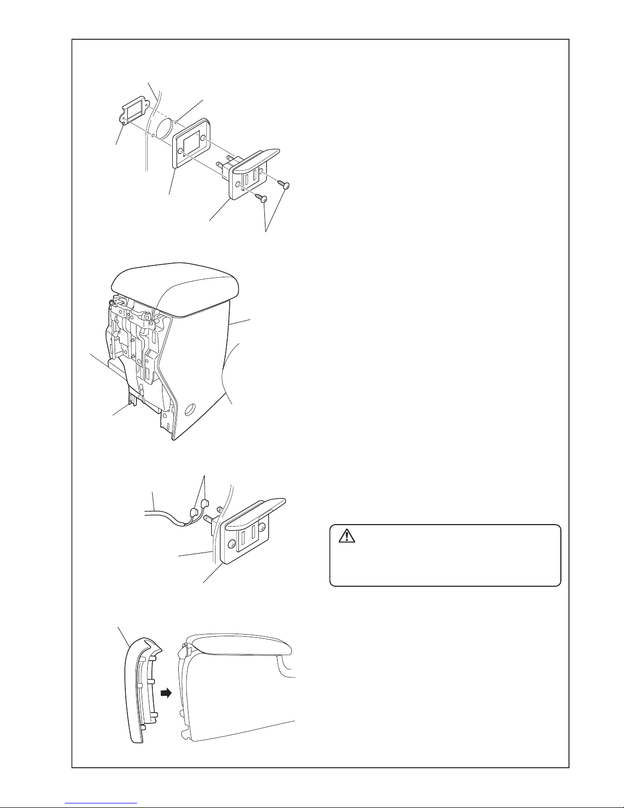
Check
DOOR
CONSOLE
Fully ungaged
CAUTION
This product requires removal of the passenger 's seat. As a result of the removal of the passenger 's
seat it will be necessary to re-calibrate the Occupant Detection System. If not properly calibrated the
Occupant Detection System may not operate as designed which may result in injuries to the front
seat passenger. Therefore, it is strongly recommended that the product be installed at an authorized
Subaru dealer.