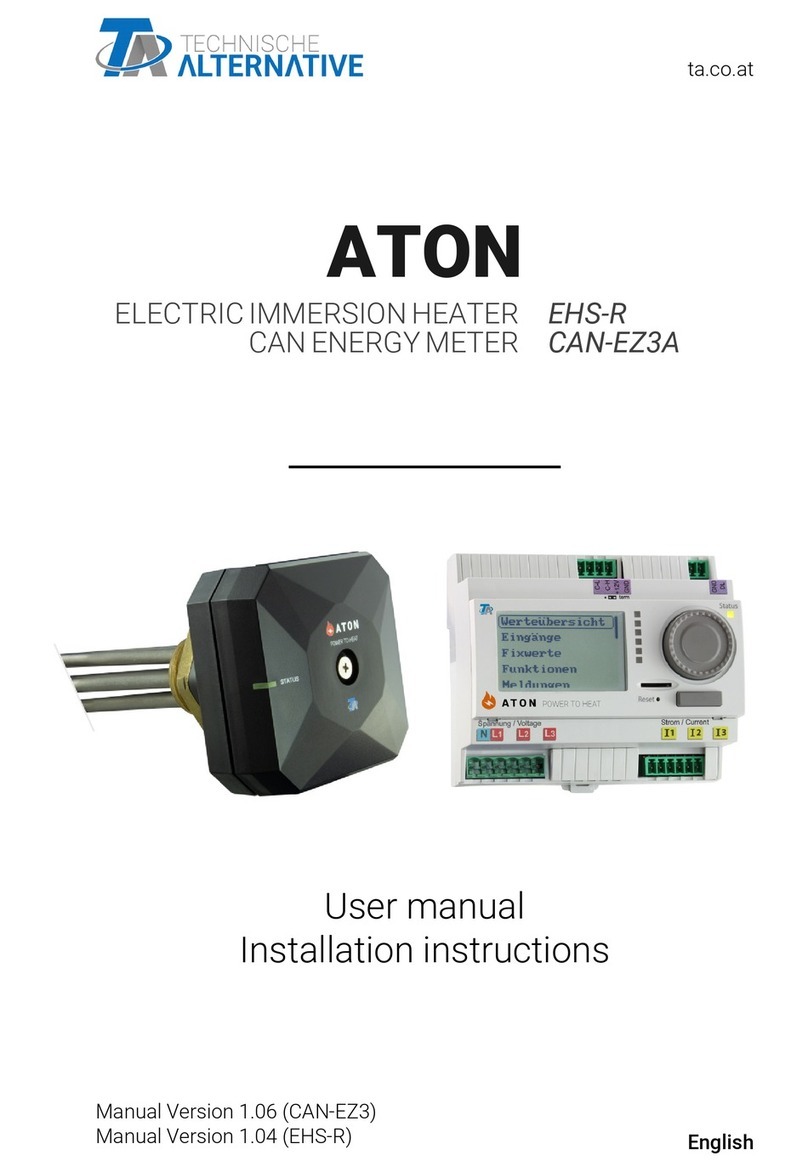
TEHNISCHE ALTERNATIVE ATON+ User manual

ta.co.at
ATON+
ELECTRIC IMMERSION HEATER EHS-R
CAN ENERGY METER CAN-EZ3
User manual
Installation instructions
English
Manual Version 1.24 (CAN-EZ3)
Manual Version 1.15 (EHS-R)

Table of contents
Safety requirements . . . . . . . . . . . . . . . . . . . . . . . . . . . . . . . . . . . . . . . . . . . . . . . . . . . . . . . . . . . 3
Maintenance . . . . . . . . . . . . . . . . . . . . . . . . . . . . . . . . . . . . . . . . . . . . . . . . . . . . . . . . . . . . . . . . . . . 4
Disposal . . . . . . . . . . . . . . . . . . . . . . . . . . . . . . . . . . . . . . . . . . . . . . . . . . . . . . . . . . . . . . . . . . . . . . 4
Introduction . . . . . . . . . . . . . . . . . . . . . . . . . . . . . . . . . . . . . . . . . . . . . . . . . . . . . . . . . . . . . . . . . . 5
Step-by-step instructions . . . . . . . . . . . . . . . . . . . . . . . . . . . . . . . . . . . . . . . . . . . . . . . . . . . . . . . 5
Factory settings . . . . . . . . . . . . . . . . . . . . . . . . . . . . . . . . . . . . . . . . . . . . . . . . . . . . . . . . . . . . . . . 6
Overview of TAPPS2 programming . . . . . . . . . . . . . . . . . . . . . . . . . . . . . . . . . . . . . . . . . . . . . . . 6
Functions . . . . . . . . . . . . . . . . . . . . . . . . . . . . . . . . . . . . . . . . . . . . . . . . . . . . . . . . . . . . . . . . . . . 7
Suggested installation . . . . . . . . . . . . . . . . . . . . . . . . . . . . . . . . . . . . . . . . . . . . . . . . . . . . . . . . . 8
Datalogging . . . . . . . . . . . . . . . . . . . . . . . . . . . . . . . . . . . . . . . . . . . . . . . . . . . . . . . . . . . . . . . . . 8
Installation and connection . . . . . . . . . . . . . . . . . . . . . . . . . . . . . . . . . . . . . . . . . . . . . . . . . . . . . . 9
Power supply . . . . . . . . . . . . . . . . . . . . . . . . . . . . . . . . . . . . . . . . . . . . . . . . . . . . . . . . . . . . . . . . . . 9
Time stamp . . . . . . . . . . . . . . . . . . . . . . . . . . . . . . . . . . . . . . . . . . . . . . . . . . . . . . . . . . . . . . . . . . . . 9
General connection of the CAN-EZ3 . . . . . . . . . . . . . . . . . . . . . . . . . . . . . . . . . . . . . . . . . . . . . . . . 10
DL bus and CAN bus connections . . . . . . . . . . . . . . . . . . . . . . . . . . . . . . . . . . . . . . . . . . . . . . . . . 11
A flow rate sensor can be connected directly to the CAN-EZ3 without an intermediate board. For this,
a ribbon cable, which is available separately, is adjusted to the required length on site. This is done
by pressing the 2nd plug onto the cable according to the following drawing.Electrical measuring 11
3-phase measuring . . . . . . . . . . . . . . . . . . . . . . . . . . . . . . . . . . . . . . . . . . . . . . . . . . . . . . . . . . 11
1-phase measuring . . . . . . . . . . . . . . . . . . . . . . . . . . . . . . . . . . . . . . . . . . . . . . . . . . . . . . . . . . 12
External hinged current transformers . . . . . . . . . . . . . . . . . . . . . . . . . . . . . . . . . . . . . . . . . . . . 12
Installation and connection . . . . . . . . . . . . . . . . . . . . . . . . . . . . . . . . . . . . . . . . . . . . . . . . . . . . . 13
Dimensioned drawing . . . . . . . . . . . . . . . . . . . . . . . . . . . . . . . . . . . . . . . . . . . . . . . . . . . . . . . . . . . 13
High limit safety cut-out (HLSC) . . . . . . . . . . . . . . . . . . . . . . . . . . . . . . . . . . . . . . . . . . . . . . . . . . . 14
Sensor installation, PWM input . . . . . . . . . . . . . . . . . . . . . . . . . . . . . . . . . . . . . . . . . . . . . . . . . . . . 14
Mains connection . . . . . . . . . . . . . . . . . . . . . . . . . . . . . . . . . . . . . . . . . . . . . . . . . . . . . . . . . . . . . . 15
Heating elements . . . . . . . . . . . . . . . . . . . . . . . . . . . . . . . . . . . . . . . . . . . . . . . . . . . . . . . . . . . . . . 15
Wireless system (CORA) . . . . . . . . . . . . . . . . . . . . . . . . . . . . . . . . . . . . . . . . . . . . . . . . . . . . . . . 16
Principles . . . . . . . . . . . . . . . . . . . . . . . . . . . . . . . . . . . . . . . . . . . . . . . . . . . . . . . . . . . . . . . . . . . . 16
Pairing CORA devices . . . . . . . . . . . . . . . . . . . . . . . . . . . . . . . . . . . . . . . . . . . . . . . . . . . . . . . . . . . 16
Relaying wireless signals . . . . . . . . . . . . . . . . . . . . . . . . . . . . . . . . . . . . . . . . . . . . . . . . . . . . . . . . 17
Deleting a pairing . . . . . . . . . . . . . . . . . . . . . . . . . . . . . . . . . . . . . . . . . . . . . . . . . . . . . . . . . . . . . . 17
CORA-DL (cable instead of wireless) . . . . . . . . . . . . . . . . . . . . . . . . . . . . . . . . . . . . . . . . . . . . . . . 18
Installation . . . . . . . . . . . . . . . . . . . . . . . . . . . . . . . . . . . . . . . . . . . . . . . . . . . . . . . . . . . . . . . . . 18
Control via PWM – without wireless connection . . . . . . . . . . . . . . . . . . . . . . . . . . . . . . . . . . . . . . 19
Notes on accuracy . . . . . . . . . . . . . . . . . . . . . . . . . . . . . . . . . . . . . . . . . . . . . . . . . . . . . . . . . . . . 20
Reset . . . . . . . . . . . . . . . . . . . . . . . . . . . . . . . . . . . . . . . . . . . . . . . . . . . . . . . . . . . . . . . . . . . . . . 21
LED status indicators . . . . . . . . . . . . . . . . . . . . . . . . . . . . . . . . . . . . . . . . . . . . . . . . . . . . . . . . . . 21
LED indicators at device start-up . . . . . . . . . . . . . . . . . . . . . . . . . . . . . . . . . . . . . . . . . . . . . . . . . . 21
Reset/pairing . . . . . . . . . . . . . . . . . . . . . . . . . . . . . . . . . . . . . . . . . . . . . . . . . . . . . . . . . . . . . . . . 22
LED status indicators . . . . . . . . . . . . . . . . . . . . . . . . . . . . . . . . . . . . . . . . . . . . . . . . . . . . . . . . . . 22
Possible LED indicators . . . . . . . . . . . . . . . . . . . . . . . . . . . . . . . . . . . . . . . . . . . . . . . . . . . . . . . . . 23
Firmware-Update via CAN-EZ3 . . . . . . . . . . . . . . . . . . . . . . . . . . . . . . . . . . . . . . . . . . . . . . . . . . . 23
Technical data . . . . . . . . . . . . . . . . . . . . . . . . . . . . . . . . . . . . . . . . . . . . . . . . . . . . . . . . . . . . . . . 24
Technical data . . . . . . . . . . . . . . . . . . . . . . . . . . . . . . . . . . . . . . . . . . . . . . . . . . . . . . . . . . . . . . . 25

3
Safety requirements
This device is state of the art and meets all necessary safety regulations. It may only be used in ac-
cordance with the technical data and the safety requirements and regulations listed below. When us-
ing the device, also observe the statutory and safety regulations apposite to the particular use. Any
other use will automatically void all warranty rights.
• Connection work and other exposure of the PCB in the immersion heater casing should only be
carried out in a dry interior room.
• It must be possible to isolate the immersion heater from the mains, in accordance with local reg-
ulations, using an omnipolar isolating facility (plug/socket or 2-pole isolator).
• The immersion heater should only be connected to a mains socket using the supplied connect-
ing cable. The connecting cable should be fitted before insertion. The mains socket must have at
least 16 A fuse protection.
• No extension cables, mains distributors or cable drums should be used.
• Before starting installation or wiring work on equipment, the immersion heater must be com-
pletely isolated from the mains and protected against a restart.
• Never pull on the mains cable, or pull the mains plug out of its socket by the cable.
• Safe operation is no longer possible if the immersion heater, or connected equipment shows
signs of visual damage, no longer functions or has been stored for lengthy periods in unfavoura-
ble conditions. If this is the case, disable the devices or equipment and secure against uninten-
tional use.
• At the immersion heater, high temperatures occasionally occur during operation, which should
be taken into consideration during installation/maintenance work. Also never touch the immer-
sion heater with wet/damp hands. Insulated footwear is recommended for installation work.
• The immersion heater may be active at a high output level for a prolonged period of time. Rele-
vant components (e.g. sockets) must be able to withstand current flows of up to 16 A for pro-
longed periods.
All installation and wiring work on the controller must only be carried out in a zero
volt state. The opening, connection and commissioning of the device may only
be carried out by competent personnel. While doing so, they must observe all lo-
cal safety requirements.

4
Maintenance
If treated and used correctly, the device itself will not require any maintenance. However, the use of
a suitable sacrificial anode in the cylinder is recommended, and if the immersion heater is used more
often than usual, it is necessary to check whether the material thickness is reduced (at least 2-3
times per year).
No components relevant to long term accuracy are subject to loading if the device is used correctly.
Consequently long term drift is extremely low. The device therefore does not require any mainte-
nance and cannot be adjusted.
The structural characteristics of the device must not be changed during repairs. Spare parts must
correspond to the original parts and must be used in accordance with the build version.
Disposal
• Devices no longer in use or beyond a state of repair must be disposed of in an en-
vironmentally responsible manner by an authorised collection point. They mus nev-
er be treated as ordinary household waste.
• We can undertake the environmentally responsible disposal of devices sold by the
Technischen Alternative company upon request.
• Packaging material must be disposed of in an environmentally responsible man-
ner.
• Incorrect disposal may result in considerable damage to the environment, as
many of the materials used require professional handling.

Introduction
5
Introduction
The ATON set comprises a CAN-EZ3A energy meter and a variable EHS-R immersion heater.
These two devices communicate wirelessly with one another. The energy meter and immersion heat-
er are connected at the factory. This means that no wireless connection settings are required. How-
ever, information can be found in chapter Wireless system.
The purpose of the CAN-EZ3A is to capture energy and calculate surplus output, e.g. in conjunction
with PV systems. Relevant values are transmitted wirelessly to the EHS-R, which in turn converts
possible surpluses into heat, instead of exporting them to the mains, which can be a less favourable
option.
The CAN-EZ3A is programmed at the factory and this programming is described in more detail in
chapter Work settings. This programming can, of course, be changed or replaced with your own pro-
gramming. The energy meter can be fully programmed via the display and control buttons/rotary dial,
but we recommend using the PC software TAPPS2 for this. Programming generated on the PC can
be loaded on to the energy meter using the supplied micro SD card.
The EHS-R immersion heater does not require any programming/parameterisation.
Step-by-step instructions
1
Are the work settings on the CAN-EZ3A suitable for the on-site requirements? (See chapter
"Work settings")
If not, adjust the existing programming or generate your own and load it on to the energy
meter. (Instructions for the programming software and available function modules under
www.ta.co.at)
2The wireless range (as described in chapter "Wireless system (x2 wireless)") should be
compared with the on-site conditions.
3Shut down the control cabinet.
4Installation of the CAN-EZ3A in the control cabinet.
5Connect a current transformer to the CAN-EZ3A.
6Connect voltage terminals to the CAN-EZ3A.
7Snap the current transformer on to phase conductors, taking into consideration the energy
direction. (Current transformer ferrite cores must be clean.)
8Connect voltage terminals to the phase conductors, taking into consideration the energy
direction.
9Installation of the EHS-R in the cylinder. (Observe information in chapter "Installation and
connection – EHS-R immersion heater", particularly information regarding the electroplat-
ing in the cylinder)
10 As soon as both devices are supplied with power, the wireless connection is established
automatically.

Factory settings
6
Factory settings
The CAN-EZ3A is programmed at the factory and this programming is described in more detail in the
following pages. This programming can, of course, be changed or replaced with your own program-
ming. The energy meter can be fully programmed via the display and control buttons/rotary dial, but
we recommend using the PC software TAPPS2 for this.
The EHS-R does not require any programming/parameterisation.
Overview of TAPPS2 programming

Factory settings
7
Functions
The primary functionality comprises the Output control of the EHS-R immersion heater and an Ener-
gy manager, in connection with a Comparison function.
• The Energy manager receives the measured output via the system value Total real power and
the set output is specified with the fixed value F1 Set output.
• In the Energy manager, Output control is stored as an included function. This means that the
output to be consumed is specified for Output control.
• The purpose of the comparison function is to limit the maximum temperature of the immersion
heater. The threshold for this is set via the fixed value F2 Maximum temperature (set to 60 °C at
the factory).
• If the maximum temperature at the immersion heater is reached, the comparison function
issues an enable for the Output control to OFF. This blocks operation of the immersion
heater.
An energy meter also runs, together with a date-specific memory. This adds up the consumption of
the immersion heater in kWh.
An optional functionality for DHW heating is also integrated. This is deactivated at the factory via the
fixed value F3 Forced operation, enable.
• In the function Time switch, a time program is stored (default Mo-Su, 17:00 - 22:00 h). Within the
time window, DHW is heated irrespective of the solar yield.
• The DHW temperature is measured with Temperature 1* at the immersion heater. This tem-
perature is increased at sensor input S1 of the EHS-R.
• The maximum temperature limit via the comparison function also affects DHW heating.
• The fixed value F4 Forced operation, set temp. specifies the set temperature for normal DHW
heating and for the functionality Charge once.
• The DHW demand switches the Output control with its Forced operation.
The range function "Fault code HLSC" evaluates the fault code and triggers the HLSC (high limit safe-
ty cut-out) message if the sensor of the EHS-R for the safety temperature limit exceeds 95 °C.
Once the HLSC fault code has been triggered, the immersion heater must be restarted manually be-
fore it is permitted to operate again (standard requirement). For this purpose, either power to the im-
mersion heater must be cut briefly or it must be restarted via the CAN-EZ3 (menu item CORA
devices).
The analogue function "Ramp" is used to slowly ramp up the power consumed by the EHS-R. This
function is deactivated at the factory by the fixed value F6 Enable ramp-up. If activated, the immer-
sion heater continues to respond as quickly as possible when the energy available to it decreases.
However, if energy suddenly becomes available to the immersion heater (e.g. because a larger con-
sumer in the household switches off), the consumed power ramps up slowly by means of the ana-
logue function Ramp. The rate of this ramp-up can be adjusted using the fixed value F8 Ramp falling
power draw (factory setting: 100 W). The ramp prevents time-delayed cycling so that the immersion
heater consumes as little non-surplus power as possible. However, when ramping starts up, any sur-
plus is exported to the grid rather than consumed.
The fixed value F7 Ramp rising power draw is intentionally set unrealistically high (factory setting:
30 kW), which means that the ramp is not effective in the direction of increasing power draw. If re-
quired, the ramp can also be activated in this direction.
A more detailed description of all function modules can be found in the corresponding operating
instructions for freely programmable controllers (www.ta.co.at).

Factory settings
8
There is also a group of functions with the heading "Extension for combination with C.M.I.". These
functions make separate records of power exported to the grid via the EHS-R and power drawn via
the EHS-R.
Suggested installation
*To ensure that Temperature 1 gives a practical value, the immersion heater's cylinder sensor S1
must be installed at the top of the cylinder. The immersion heater must be installed horizontally in
the cylinder.
Datalogging
The following values are logged at the factory:
• EHS-R Temperature 1 (sensor input S1 of the immersion heater)
• EHS-R Current output in kW
• CAN-EZ3A Electrical power (total real power)
• Function Energy meter (kWh total)
Datalogging on SD card is deactivated at the factory.

Installation and connection
9
Installation and connection
The CAN-EZ3 is installed in a meter box in accordance with local regulations. It can be snapped on
to a top-hat rail (DIN support rail TS35 to EN 50022).
The 2-pole connectors of the current transformers are connected to the CAN-EZ3 and folded over the
cores. When doing this, pay attention to the correct assignment (I1 - I3) in accordance with the volt-
age connections and a positive phase sequence.
For voltage measuring, the required wires are connected to the voltage terminals in the CAN-EZ3.
The connection of sensors, and CAN and DL buses is carried out using the supplied connectors
Power supply
The CAN-EZ3 is supplied with power via the voltage measuring connection U1 (first phase).
Time stamp
The CAN-EZ3 has a real time clock and, as node 1 in the CAN bus network, can therefore transmit the
time and date to other devices.
Caution! The surfaces of the current transformer ferrite cores must be completely clean. Even tiny
dust particles or greasy films can severely affect the measuring result. These surfaces must there-
fore be cleaned with a clean, lint-free cloth or clean fingers before closing.

Installation and connection
10
General connection of the CAN-EZ3
The CAN-EZ3 must always be connected by qualified personnel, taking into account the conditions
on site and local safety regulations. The safety requirements on page 5 must also be observed.
The following diagram is only an example of the installation of a CAN-EZ3 in a typical TN-S system
with surplus power supply.
NZHS Normal supply main switches
HAS Grid connection fuses
ENS Device for grid monitoring with associat-
ed switching element
FI Residual current device
MCB Miniature circuit breaker
Wh Electricity meter of the energy supplier
Device is internally fused; only the supply
cable to the device must be fused
Appropriate fuse protection by the MCB
(A) should be selected according to the
cable diameter.

Installation and connection
11
DL bus and CAN bus connections
A flow rate sensor can be connected directly to the CAN-EZ3 without an intermediate board. For
this, a ribbon cable, which is available separately, is adjusted to the required length on site. This is
done by pressing the 2nd plug onto the cable according to the following drawing.Electrical
measuring
3-phase measuring
All 3 phase conductors (L1 - L3) are connected to voltage terminals L1-L3 and the neutral conductor
to the N terminal. The 3 external hinged current transformers are connected to terminals I1 – I3 in
the correct sequence and folded over the wires to be measured.
For single measurements, it is possible to set the "Phase simulation" parameter in the General set-
tings to "Yes". In this case, the values (voltage / cos phi / output) for L2 and L3 are simulated inter-
nally using L1. Phase simulation is based on a clockwise rotating field, therefore a clockwise rotating
field must also be observed for current measurement at I2 and I3.
This results in less precise measuring. When phase simulation is activated, phases L2 and L3 are
CAN bus
(C-L, C-H
+12 V, GND)
CAN-Low, CAN-High, +12 V, earth
The principles of bus cabling are described extensively in the manuals for the free-
ly programmable controllers and must be observed.
Modbus Interface for Modbus RTU485 (as master or slave)
DL bus
DL bus interface for DL sensors (e.g. FTS-DL (with intermediate board))
Parameterisation: DL bus menu (any analogue input)
Connection between DL and GND
Ext. connec-
tion Antenna
No screws should be used to secure the antenna cable – press and pull to con-
nect and terminate. The antenna itself is intended for mounting outside the meter
box. The antenna should not be fitted directly on metal (e.g. meter box).
S0 output
The connection for S0 signals is located on the device's lower terminal strip
(graphic on page 11).
This output can emit pulses with max. 20 Hz and a pulse duration of at least
25 ms. Either power drawn from grid or power exported to grid is issued; adjusta-
ble in the standard settings.

Installation and connection
12
output as 0. When phase simulation is deactivated, the high-resistance voltage input may result in
random values being displayed at L2 and L3 due to interference effects. This can be eliminated by
additionally routing the neutral conductor N to voltage inputs L2 and L3.
1-phase measuring
Only the phase conductor (to voltage terminal L1) and the neutral conductor N are connected. An ex-
ternal hinged current transformer is connected to terminal I1 and folded over the wire to be meas-
ured.
The "Phase simulation" parameter is irrelevant for this.
External hinged current transformers
Ensure that the current transformers are assigned correctly (I1 to L1, I2 to L2 and I3 to L3) and that
the energy direction is observed.
PLEASE NOTE: Before snapping the current transformer onto the phase conductors, they must al-
ready be connected to the CAN-EZ3. Otherwise the current transformers can be damaged.
Each external current transformer is labelled with "K L", whereby the energy direction must be
from K to L for positive metering.
The poles of the cable connecting the electricity sensor and the energy meter must not be swapped.
The white cable must be on the left and the black cable on the right.
Each current transformer must be closed carefully by clicking the snap fastener securely into place.
If the energy direction is changed, the energy meter counts in the negative.
energy direction
Mains side building side
This cable is either white
or red.

Installation and connection
13
Installation and connection
Dimensioned drawing
cold zone = distance from threaded head, which is not heated (120 mm)
The immersion heater must be installed horizontally in the cylinder. The ventilation slots must be
at the top and bottom.
Do not start up the immersion heater if it is not in water.
Use in DHW cylinders
We expressly advise against using our immersion heater in DHW cylinders!
The immersion heater is intended for installation in buffer cylinders in which the
same heating water always circulates.
As of serial number EHSR-002956, the immersion heater comes with a Teflon coating. This en-
hances its suitability for enamelled cylinders. However, the use of a suitable sacrificial anode in the
cylinder is recommended, and this should be regularly checked.
We do not offer any guarantee or warranty in the case of limescale or galvanic corrosion!
Observe the safety requirements on page 3!

Installation and connection
14
High limit safety cut-out (HLSC)
The EHS-R has a sensor for the high limit safety cut-out. This is a PT1000 sensor in a sensor well
between the heating elements. It is connected at the factory at the connection shown below.
When a temperature of 95 °C is reached at the STB sensor, the immersion heater is deactivated. The
immersion heater must then be restarted manually (click button once, disconnect and reconnect
power cable of immersion heater, or restart via the CAN-EZ3).
The electronics temperature is also monitored. Their maximum temperature is 75 °C (5 K hysteresis).
Sensor installation, PWM input
The EHS-R has 2 sensor inputs, which are only suitable for connection of PT1000 sensors. The
measurements of these sensors are transferred via the CORA wireless connection. This establishes
the connection for PWM control. More detailed information can be found in the chapter of the same
name.

Installation and connection
15
Mains connection
Heating elements
The 3 heating elements are connected at the factory and fully wired. For any installation/mainte-
nance work, ensure correct wiring/connection.
The EHS-R has 3 heating elements:
• 750 W controllable
• 750 W not controllable
• 1500 W not controllable
The connections of the heating elements (as they are routed from the threaded head and through the
PCB) must not be interchanged. By the orientation of the screw at the edge of the threaded head, the
heating elements and their connections can be identified.
1 750 W not controllable
2 1500 W not controllable
3 750 W controllable
4 Neutral conductor 1500
W not controllable
5 Neutral conductor 750 W
not controllable
The two neutral conductors (4 and 5) can be swapped. The two connections of the controllable heat-
ing element (3) are reverse polarity-protected. For the remaining wires, the polarity must be ob-
served.
L Phase
N Neutral conductor
Pe Earth conductor
Heating elements
Connections on PCB

Wireless system (CORA)
16
Wireless system (CORA)
Principles
The wireless system comprises multiple CORA devices (e.g. CAN-EZ3 and EHS), which communicate
with one another, exchange data or transfer firmware. This functionality cannot fully replace the CAN
bus.
For the wireless system, the CAN-EZ3 has an external antenna. The antenna itself is intended for
mounting outside the meter box. The antenna should not be fitted directly on metal (e.g. meter box).
The wireless range is around 1000 m outdoors, and typically 30 m in buildings (through approx. 2
walls/ceilings, depending on thickness and material). Up to 3 additional wireless devices can be
used as a bridge to enable data to be exchanged under deviating conditions.
A CAN-EZ3 can be paired with maximum 12 CORA devices.
RCV-DL, GBS-F and RAS-F devices cannot be used.
Wireless system settings can be found in the main menu item CORA devices.
Pairing CORA devices
In the ATON set, the included CAN-EZ3A energy meter and the EHS-R immersion heater are already
paired at the factory.
In the main menu, under "CORA devices", a New CORA device is selected.
Once the device type has been selected, additional setting options appear.
Switch to device parameters
Pairing status
Wireless or cable connection
Specify CORA ID from target device...
...and select Pair
The target device must have Allow pairing enabled. Information about this can be found in the oper-
ating instructions for the relevant device.
To pair an additional device, navigate back to the Devices menu and create another New device.
If Manual mode is set to ON, the item Output appears under it. Here, you can adjust the set output
for manual mode.
If Connect automatically is set to Yes, when the wireless signal is lost, the system automatically at-
tempts to restore the connection.

Wireless system (CORA)
17
Relaying wireless signals
CORA devices can relay signals from other devices. All required settings for this are carried out at
the device, which transmits the signal to be relayed. Pairing with devices that simply relay signals is
not required.
During parameterisation of the CORA device, simply enter the CORA ID of the relaying devices under
the items HOP1-3 (depending on how many relays should occur).
RCV-DL, GBS-F and RAS-F devices cannot be used.
Example: The CORA 1 device should control the CORA 3 wirelessly, but cannot reach it due to the
local conditions. However, CORA 1 can reach CORA 2, and CORA 2 can reach CORA 3.
During parameterisation on CORA 1 (= pairing with CORA 3), the CORA ID
of CORA 3 is entered under CORA ID, and the CORA ID of CORA 2 is en-
tered under HOP1.
No settings are required on CORA 2. This device relays the signals inde-
pendently.
No settings are required on CORA 3 either.
The only change to the pairing process is that CORA IDs are entered under HOP1-3.
To enable additional devices to relay the signal, they should be specified in the corresponding order
under HOP2 and then under HOP3. A data packet is sent by the transmitter to HOP1, HOP2, HOP3
and then to the target device (= "CORA ID"), where defined.
The entry 00000000 means that no relaying will occur.
Deleting a pairing
Under the tab FiD is the item Delete CORA device.

Wireless system (CORA)
18
CORA-DL (cable instead of wireless)
From version 1.08, CORA devices can also be connected to the CAN-EZ3 via a cable. This replaces
all functions of the wireless system. A CORA device cannot be run with a wireless and a cabled con-
nection at the same time.
For use with a cable, set "Connection" to CORA-DL in the parameters of
the set CORA device.
Under "CORA ID", enter the ID of the device to be connected. This can usu-
ally be found on a label on the device.
Installation
To use a CORA device via CORA-DL, connect it to the DL bus of the CAN-EZ3.
Devices connected via CORA-DL do not affect the DL bus load.
On the immersion heater:
The PWM input on the immersion
heater also acts as the CORA-DL
interface. The CAN-EZ3A is con-
nected to the PWM input if wire-
less communication is not being
used.

PWM control
19
Control via PWM – without wireless connection
To operate the EHS-R without a wireless connection (e.g. in conjunction with controller UVR16x2 or
CAN-EZ3 and output extension AO4-DL), the immersion heater has a PWM input. 10-90% PWM cor-
responds to 0-3000 W output, but operation only starts at min. 45 W (equates to around 12% PWM).
Important: If an active wireless connection is available (paired and signals being received), the PWM
input is inactive. If the immersion heater is controlled via the PWM input, the wireless pairing of other
devices with the EHS-R must be deleted.
For the PWM input connection graphic, see chapter "Sensor installation, PWM input".

Notes on accuracy / Reset / LED status indicators
20
Notes on accuracy
The accuracy of all measured energies and energy flows depends on many factors and is to be sub-
ject to closer consideration here.
• PT1000 class B temperature sensors have an accuracy of +/- 0.55 K (at 50 °C).
• Errors in temperature capture by the x2 device are typically +/- 0.4 K per channel.
For an assumed spread of 10 K, these two measuring errors result in a maximum measuring error
between the flow and return of +/- 1.90 K = +/- 19.0 % for class B and +/- 13.0 % for class A.
• At a lower spread, the percentage measuring error increases
• The accuracy of the FTS 4-50DL flow sensor is approx. +/- 1.5 %
• The measuring error of electrical energy capture is +/- 3 % (at cos phi = 0.6)
In the worst case scenario, the maximum overall measuring error for heat metering therefore equals:
1.19 x 1.015 = 1.208
This means heat metering accuracy of +/- 20.8 % in the worst case scenario (at 10 K spread, without
calibrating the temperature sensors), although all measuring errors would then skew the results to
the same extent.
Experience has shown that a worst case scenario never actually occurs and in an unfavourable sce-
nario, half of this value can be expected. However, even 10.4 % is not justifiable.
After calibrating the temperature sensors (see above), the measuring error of the overall tempera-
ture measurement reduces to a maximum 0.3 K. Relative to the spread of 10 K as assumed above,
this equals a measuring error of 3 %.
The maximum overall measuring error for the performance factor therefore equals:
1.03 x 1.015 = 1.045
At a 10 K spread and with calibrated temperature sensors, heat metering accuracy therefore im-
proves for the worst case scenario to +/- 4.5 %.
This manual suits for next models
2
Table of contents
Other TEHNISCHE ALTERNATIVE Heating System manuals
Popular Heating System manuals by other brands
Armstrong
Armstrong 3760 ProDose Series Installation and operating instructions

Carrier
Carrier 48EJ user manual
Applied Air
Applied Air DFL 035 Technical guide

Airia
Airia Lifebreath RNC5-ES Homeowner's guide
Viessmann
Viessmann Vitocrossal 300 CT3 SERIES Safety and installation requirements
S&P
S&P SLIM Series manual

Nordyne
Nordyne CMF80-PG Owner's manual and installation instructions

ZappBug
ZappBug Room owner's manual

MAREX
MAREX INFRARED HEATING PANELS instruction manual
Reflex
Reflex Variomat Original operating manual
Vortice
Vortice Avel D H Box Instruction booklet
Mitsubishi Electric
Mitsubishi Electric VL-250CZPVU-R-E installation manual
