Teikoku USA | Chempump Instruction Manual IOM-22-ALP13SE-1122
4
Contents
Introduction 2
Overview 5
1. General Information 6
2. Installation 9
3. Operation 12
4. Maintenance 15
Appendix 20
Appx. A. Motor Pump Data Sheet...........................................21
Appx. B. Outline R-210P-0104Q, 13-SE ..................................22
Appx. C. Sectional View (R42-217P4BL-0104QM4-J)...............23
Appx. D. Type-R (Plan 13-SE) Installation Instructions...............24
Appx. E. Troubleshooting .......................................................25
Appx. F. TRC-1 Information Sheet..........................................26
Appx. G. NH3Reference Curve (20°F)......................................27
Appx. H. NH3Reference Curve (-50°F) ....................................28
Appx. I. Type 217-120 Motor Data Sheet...............................29
Appx. J. 13-SE Temperature/Pressure Profile ...........................30
Appx. K. Optional Rotor Cavity Thermowell ............................31
Appx. L. Terminal Box Assembly .............................................32
Appx. M. Allowable Piping Forces and Moments......................33
Appx. N. Optional TSG NH3Speed Control Panel ....................34
Appx. O. Wiring Diagram Optional TSG NH3
Speed Control Panel.................................................35
Appx. P. Decontamination Form.............................................36
Appx. Q. Teikoku Pump Repair Policy ......................................39
Figures
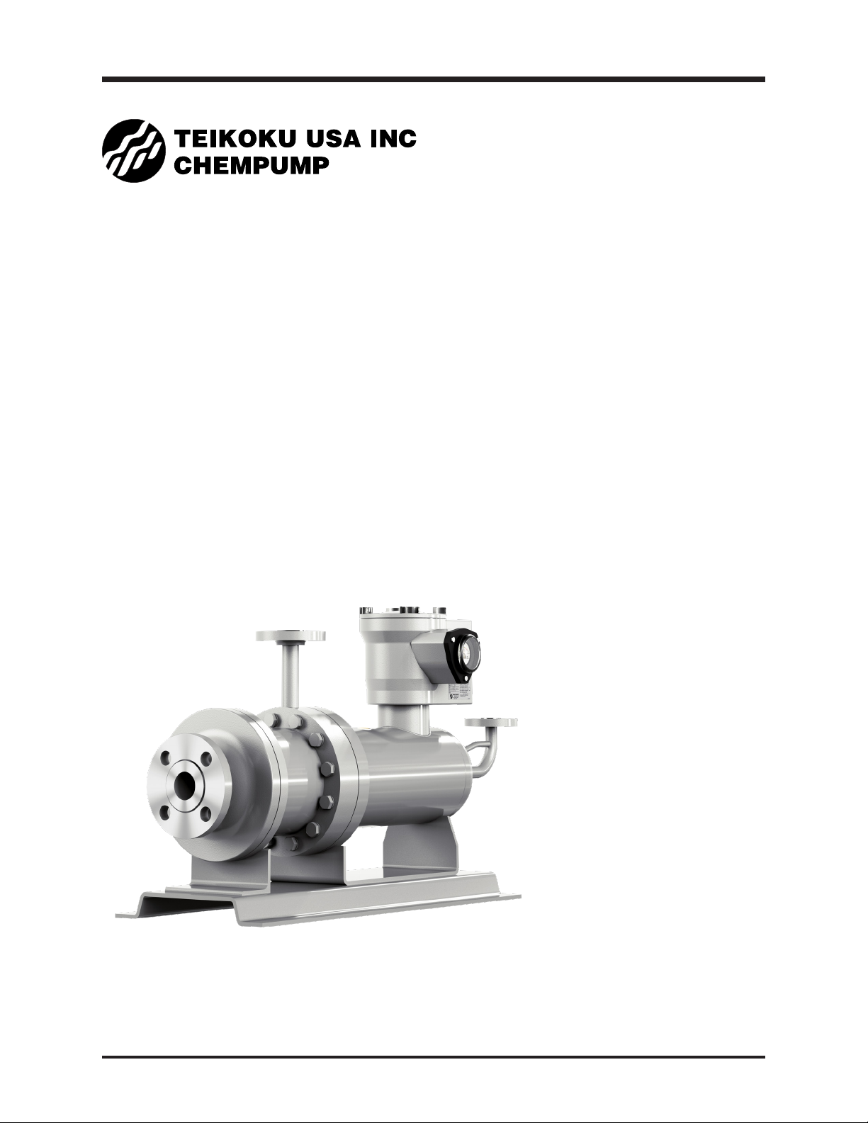
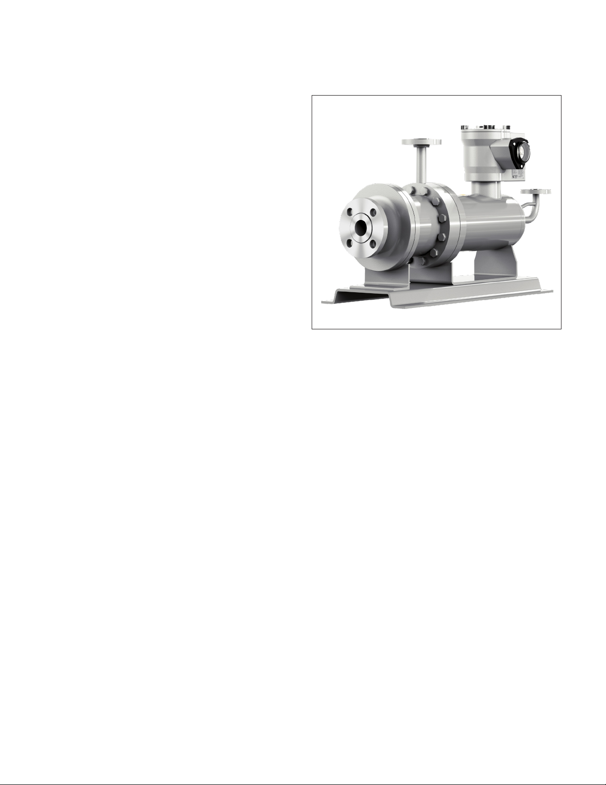
Figure 1-1. Type-R (Plan 13-SE) Reverse Circulation ALP
Multi-stage Pump ...................................................6
Figure 1-2. Flow Path ................................................................7
Figure 1-3. Typical NH3Transfer System Requirements................8
Figure 2-1. Teikoku TRG Bearing Wear Monitor .......................10
Figure 3-1. Teikoku Rotary Indicator TRC-1 ..............................13
Figure 4-1. First Bowl Bearing – Only Straight Grooves ............17
Figure 4-2. Motor Bearings – Spiral and Straight Grooves .......17
Figure 4-3. Bearing Wear Limits...............................................18
Figure 4-4. Measurement of “g” Gap......................................18
Figure 4-5. Type-R (Plan 13-SE) Model Number Indentification
Code Example .......................................................19
Tables
Table 2-1. Conditions indicated on the TRG Meter ..............10
Table 2-2. Inverter Parameter Settings.................................11
Table 4.1 Recommended Tools...........................................15
Table 4-2. Impeller Axial Gap ..............................................18
Table 4-3. Bearing Wear Limit .............................................19
Table 4-4. End Play .............................................................19
Table 4-5. Tightening Torques .............................................19
Table 4-6. Torque Values for Motor Terminal Connections
– Terminal Box and Connection Stud Size............19
Table 4-7. Pump Ring Clearance (Standard Horizontal
Pump) ................................................................19