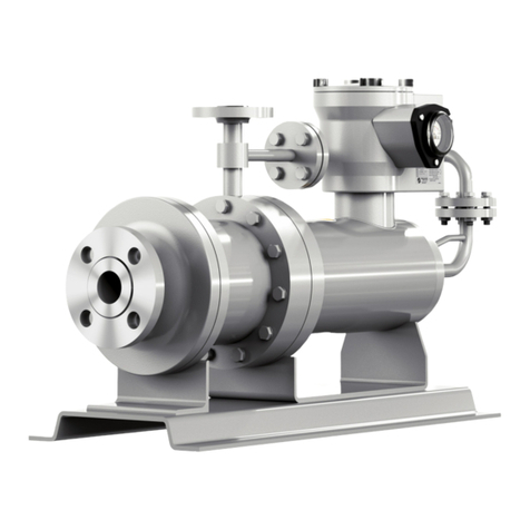
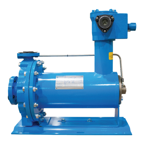
Teikoku API-685 User manual

INSTRUCTION MANUAL
for Installation, Operation, and Maintenance
HE-10677-P June 2020
TEIKOKU
REVERSE CIRCULATION PUMP
TYPE-R (API-685 Plan 13-SE)
For Refrigeration Applications Only

Thank you for purchasing the Teikoku Type-R (Plan 13-SE) refrigeration canned motor pump.
Please carefully read this instruction manual and all Safety Warnings prior to use.
A Quick Start Guide is included in the Appendix of this manual.
Introduction
Safety Terms
Please pay close attention to these terms. When you see them
in this manual, read the information thoroughly and follow the
instructions given.
Attention!
Indicates careful attention is required. The instruction in-
cludes protective information for the device and product.
Caution!
Ignoring this warning can cause personal injury and/or
damage to the device and product.
Hazard!
Ignoring this warning can cause serious injury or even
death. It can also be used to alert against unsafe practices.
NOTE: Information included in NOTES gives additional helpful
information and recommendations.
Applicable Standards and Regulations
The Teikoku Type-R (Plan 13-SE) pump conforms to the follow-
ing standards:
1. Japanese Industrial Standard (JIS)
2. Japan Electrical Manufacturers’ Standard (JEM)
3. American Society of Mechanical Engineers (ASME) B-16.5
4. Canadian Standards Association (CSA): UL 778 CSA
22.2 No 108
5. International Institute of Ammonia Refrigeration (IIAR):
ANSI/IIAR 2-2014
Product Warranty Period
This product is warranted for two years from date of delivery.
Please refer to Teikoku USA’s Terms and Conditions of Sale for
additional warranty coverage and restrictions.
Rights
All rights on products manufactured by Teikoku, corresponding
software, and this instruction manual are registered to Teikoku
Electric Mfg Co., Ltd.
It is not permitted to reproduce or transmit any portion of this
instruction manual unless prior written consent has been ob-
tained from Teikoku USA Inc., Teikoku Electric Mfg Co., Ltd. or
its subsidiaries.
Teikoku Rotary GuardianTM and TRGTM are trademarks of
Teikoku Electric Mfg. Co., Ltd.

Teikoku USA | Chempump Instruction Manual HE-10677-P (1018)1
Attention!
Do not run dry!
If the pump is allowed to run dry, the bearings, sleeves,
and other components could be damaged and serious
overheating of the motor windings can occur.
Attention!
Avoid rapid temperature changes!
Large changes in temperature must be avoided. Rapid
changes can cause leaks to occur in gaskets. Published
procedures for proper heating and cooling must be fol-
lowed. If published procedures are not available, check
with Teikoku before operating the equipment.
Caution!
Hot – Do not touch!
Motor and pump can be hot, even when pumping
cold liquids.
Caution!
If motor trips, do not restart before determining
the cause!
Restarting the motor before ascertaining the cause may
result in excessive heat, causing pump or motor failure.
Hazard!
Do not remove internal bolts in terminal box.
If it is necessary to remove the terminal box for any reason,
first loosen the bolts by 2 or 3 turns to check if any internal
pressure or liquid is present. You must take measures if the
possibility exists that the gas or liquid is toxic or hazardous
to personnel or the environment.
Hazard!
Do not remove any bolts on pump, motor, or
drain plugs!
The internal pressure can be higher than the atmosphere.
Ensure that the pump and motor are properly de-pressur-
ized and decontaminated prior to performing any work
Proper protective measures must be taken if the possibility
exists that the gas or liquid is toxic or hazardous to person-
nel or the environment.
Hazard!
Always assume that there is liquid left in the pump!
There is always the possibility that residual liquid could
remain in the pump and motor in spite of thorough de-
contamination. Pay particular attention to the clearance
between the shaft and the impeller, bearings, sleeves,
bearing housings and gaskets. You must take adequate
precautions to protect personnel and the environment if
the liquid could be considered hazardous.
Safety Warnings
Important:
Before operating the canned motor pump, read these Safety Warnings
and this entire Instruction Manual to avoid improper operation.
It is essential for your safety and to avoid disaster.

Teikoku USA | Chempump Instruction Manual HE-10677-P (1018)2
Contents
Introduction 2
Overview 2
1. General Information 3
2. Installation 5
3. Operation 8
4. Maintenance 11
Appendix 16
A. Quick Start Guide ......................................................17
B. Reverse Circulation (4N-7653) .....................................18
C. Troubleshooting .........................................................19
D. Sectional View (6A-8901) ..........................................20
E. TRC-1 Information Sheet .............................................21
F. Decontamination Form ...............................................22
Figures
Figure 1-1. Reverse Circulation Type-R (Plan 13-SE) ...................3
Figure 2-1. Teikoku Type-R (Plan 13-SE) TRG ..............................7
Figure 2-2. Teikoku Type-R (Plan 13-SE) 460 Volt, 3-Phase..........7
Figure 3-1. Teikoku TRC Rotation Indicator ................................9
Figure 4-3. Bearing Wear Limits...............................................13
Figure 4-4. “g” Gap................................................................13
Figure 4-1. Front Bearing – Only Spiral Grooves ......................13
Figure 4-2. Rear Bearing – Spiral and Straight Grooves ............13
Figure 4-5. Type-R (Plan 13-SE) Model Number Indentification
Code Example .......................................................14
Tables
Table 2-1. Conditions indicated on the TRG Meter.....................6
Table 4-1. Bearing Wear Limit..................................................14
Table 4-2. Adjusting Value of Gap “g” ....................................14
Table 4-3. End Play..................................................................14
Table 4-4. Tightening Torques..................................................14
Table 4-5. Torque Values for Motor Terminal Connections –
Terminal Box and Connection Stud Size ...................14
Table 4-6. Motor Frame and Terminal Box Size.........................14
Table 4-7. Pump Ring Clearance (Standard Horizontal Pump) ...15
Overview
Teikoku Type-R (Plan 13-SE) sealless canned motor pumps are
designed for the industrial refrigeration market and offer an
advanced low probability, true secondary containment, envi-
ronmentally friendly alternative to sealed pumps and single
containment sealless pumps.
Care should be exercised upon installation, start up, removal and
maintenance of the pumps. Recommended safety equipment
should be used at all times.
This manual, containing basic instructions for installation, op-
eration and maintenance of the Teikoku Type-R (Plan 13-SE), is
designed to assist you in obtaining this service. It is important
that the persons responsible for the installation, operation, and
maintenance of the pump read and understand this manual
thoroughly.
The Teikoku Type-R (Plan 13-SE) pump is supplied with the
Teikoku Rotary Guardian (TRGTM), the radial monitoring system
of the rotating assembly of a Teikoku canned motor pump. The
TRG monitors bearing wear and gives a direct readout as to bear-
ing condition. The TRG is mounted on the electrical junction box
as standard.

Teikoku USA | Chempump Instruction Manual HE-10677-P (1018)3
1.General Information
1.1 General Design and Operation
The Teikoku Type-R (Plan 13-SE) is a combined centrifugal pump
and squirrel cage induction electric motor built together into a
single hermetically-sealed unit. The pump impeller is of the closed
type, and is mounted on one end of the rotor shaft which extends
from the motor section into the pump casing. The rotor is sub-
merged in the liquid being pumped and is, therefore, “canned”
to isolate the motor rotor from contact with the liquid. The stator
winding is also canned to isolate it from the liquid being pumped.
Liquid film journal bearings are submerged in system liquid and
are therefore lubricated by the process liquid.
The Teikoku Type-R (Plan 13-SE) has only one moving compo-
nent, a combined rotor-impeller assembly that is driven by the
induced magnetic field of an induction motor. A portion of the
pumped liquid is allowed to circulate through the rotor cavity to
cool the motor and lubricate the bearings. The stator windings
are protected from contact with the circulating liquid by a corro-
sion resistant, non-magnetic, alloy liner, which completely seals or
cans the stator winding.
Flow paths of the Teikoku Type-R (Plan 13-SE) reverse circulation
pumps are shown in Figure 1-1. The circulating liquid is channeled
into the motor section by holes drilled in the front bearing hous-
ing. A portion of the circulating liquid lubricates the front liquid
film journal bearing and returns to the rear of the impeller. The
remainder of the circulating liquid passes over the rotor, cools
the motor, lubricates the rear liquid film journal bearing and then
exits the rear bearing housing returning to the vapor space of the
suction tank via the reverse circulation line. The Teikoku Type-R
(Plan 13-SE) reverse circulation design avoids the heated circulat-
ing liquid returning directly to the pump suction.
The Teikoku Type-R (Plan 13-SE) offers advanced low probability
true secondary containment as a standard design feature. In the
event of a failure of the primary containment can, the stator as-
sembly in conjunction with the leak proof terminal plate assembly
provides the secondary containment. This design prevents any re-
lease of the process liquid out to the atmosphere.
A standard feature of the Teikoku Type-R (Plan 13-SE) is the pat-
ented Teikoku Rotary Guardian (TRG™). The TRG is an electrical
meter that continuously monitors the condition of the bearings.
For more information on the TRG see Section 2.3.3.
The Teikoku Type-R (Plan 13-SE) sealless pump is a precision built
unit that with proper operation and maintenance will provide
years of trouble-free, leakproof service. The entire unit is mount-
ed on a fabricated steel base cradle. Operation is unaffected by
the mounting or operating position, eliminating the need for any
costly alignment procedures.
Figure 1-1. Reverse Circulation Type-R (Plan 13-SE)

Teikoku USA | Chempump Instruction Manual HE-10677-P (1018)4
1.2 Stator Assembly
The stator assembly consists of a set of three-phase windings.
Stator laminations are of low-silicon grade steel. Laminations
and windings are mounted inside the cylindrical stator band. End
bells, welded to the stator band, close off the ends of the stator
assembly. The stator liner is, in effect, a cylindrical can placed in
the stator bore and welded to the rear end bell and front end bell
to hermetically seal off the windings from contact with the liquid
being pumped.
Terminal leads from the windings are brought into an electrical
terminal box. Motor lead wires are isolated from the users’ con-
duit line by a leakproof terminal plate assembly mounted inside
the terminal box. The design of the stator assembly in conjunction
with the leakproof terminal plate assembly provides an advanced
low probabilty true positive secondary containment.
1.3 Rotor Assembly
The rotor assembly is a squirrel cage induction rotor constructed
and machined for use in the Teikoku Type-R (Plan 13-SE). It con-
sists of a machined corrosion-resistant shaft, laminated core with
cast aluminum bars and end rings, corrosion-resistant end covers,
and a corrosion-resistant can.
The rotor end covers are welded to the shaft and also to the
rotor can which surrounds the outside of the rotor, thus her-
metically sealing off the rotor core from contact with the liquid
being pumped.
The impeller is keyed to the shaft and held in place with a bolt and
lockwasher. The shaft is fitted with replaceable shaft sleeves and
thrust collars. These parts are pinned or keyed to prevent rotation.
Axial movement is restricted by the thrust collars contacting the
face of the front and rear bearings.
1.4 Liquid Film Journal Bearings
The liquid film journal bearings for the Teikoku Type-R (Plan
13-SE) are carbon graphite as standard and are machined with
special helix grooves through the bore to assure adequate liquid
circulation at the journal area. Each liquid film journal bearing is
manufactured to close tolerances for a high degree of concentric-
ity and is held in a bearing housing by a retaining screw. Liquid
film journal bearings are easily replaced by removing the retaining
screw and sliding the bearing from its housing.
1.5 Thrust Collars and Shaft Sleeves
All Teikoku Type-R (Plan 13-SE) models are equipped with thrust
collars, providing a replaceable surface against which axial loads
can be carried during process upset conditions. The shaft is also
fitted with replaceable shaft sleeves. Both the thrust collars and
shaft sleeves are constructed of 316SS with a Stellite wear surface
for long life. These parts are pinned or keyed to prevent rotation.
1.6 Cooling Flow
Flow paths of the Teikoku Type-R (Plan 13-SE) reverse circulation
pumps are shown in Figure 1-1. The circulating liquid is chan-
neled into the motor section by holes drilled in the front bearing
housing. A portion of the circulating liquid lubricates the front
liquid film journal bearing and returns to the rear of the impeller.
The remainder of the circulating liquid passes over the rotor cools
the motor, lubricates the rear liquid film journal bearing and then
exits the rear bearing housing returning to the vapor space of the
suction tank via the reverse circulation line. The Teikoku Type-R
(Plan 13-SE) reverse circulation design avoids the heated circulat-
ing liquid returning directly to the pump suction.
1.7 Automatic Thrust Balance
Based on hydraulic principles, Teikoku Type-R (Plan 13-SE) au-
tomatic thrust balance is accomplished by the pressure of the
pumped liquid itself, operating in a balance chamber at the front
and rear of the impeller.
When a change in load shifts the position of the impeller away
from the balance condition, there is an equalizing change of
hydraulic pressure in the balance chamber, which immediately re-
turns the impeller-rotor assembly to the balanced position.

Teikoku USA | Chempump Instruction Manual HE-10677-P (1018)5
2.Installation
2.1 Receipt Inspection
1. Visually inspect the shipping container for evidence of dam-
age during shipment.
2. Check unit to see that suction, discharge, and any other con-
nections are covered.
3. Inspect the suction, discharge and any other connections gas-
ket seating surface to be certain that they are clean of foreign
matter and free from nicks, gouges, and scratches.
4. Check all nameplate data against shipping papers.
5. Verify receipt of the reverse circulation line restriction orifice.
2.1.1 Storage Note
In situations where a Teikoku Type-R (Plan 13-SE) is to be stored
for a period of time prior to installation and where the climate
experiences wide temperature changes and high humidity,
the terminal box, suction and discharge flange, and any other
openings must be sealed to prevent moisture from entering the
internals of the pump. Teikoku's long term storage procedures are
available upon request.
2.2 Structural
The pump design and construction eliminates the necessity of
aligning the pump and motor. The pump should be supported
from the mountings provided. It should be mounted in such a way
as to have its weight properly supported. Suction and discharge
piping must be properly supported and aligned so that no strain
is placed on the pump casing.
1. Remove burrs and sharp edges from flanges when making
up joints.
2. When connecting flanged joints, be sure inside diameters
match within 1/16" so as not to impose a strain on the
pump casing.
3. Use pipe hangers or supports at intervals as necessary.
2.2.1 Pump Location
Locate the pump as close as possible to the liquid supply with a
positive suction head. Location of the pump and arrangement
of the system should be such that sufficient NPSH (Net Positive
Suction Head) is provided over vapor pressure of the liquid at the
pump inlet. NPSH requirements at the design point are stated on
the pump order data sheet.
NOTE: Experience has proven that most pump troubles result
from poor suction conditions including insufficient NPSH. The
suction line must have as few pressure drops as possible and avail-
able NPSH MUST be greater than required NPSH.
Depending on job conditions, available NPSH can sometimes be
increased to meet the NPSH required by the pump for satisfac-
tory operation. NPSH can be tailored by changes in the piping, in
liquid supply level, and by several other methods. Refer to Appx.
C. Troubleshooting.
2.2.2 Mounting and Alignment
Base plate assemblies are offered on all models. Simply set the
pump on a foundation strong enough to support its weight. There
is no need to bolt down or grout a Teikoku Type-R (Plan 13-SE).
Be sure that the suction and discharge piping is properly aligned so
that no strain is placed on the pump casing by out-of-line piping.
2.2.3 Piping Data
Observe the standards of the Hydraulic Institute and International
Institute of Ammonia Refrigeration when sizing and making up
suction and discharge piping. Follow these procedures:
1. Remove burrs and sharp edges when making up joints.
2. When using flanged joints, be sure inside diameters match
properly. When gasketing flanged joints, do not cut flow hole
smaller than flange opening.
3. Use pipe hangers or supports at necessary intervals.
4. Provide for pipe expansion when required by liquid
temperature.
5. When welding joints, avoid possibility of welding shot entering
the suction or discharge line, and thereby entering the pump.
Caution!
Do not weld pipe when it is connected to pump.
6. Do not spring piping when making up any connections.
7. Make suction piping as straight as possible, avoiding unneces-
sary elbows. Where necessary, use 45-degree or long-sweep
90-degree fittings.
8. Make suction piping short, direct, and never smaller in diam-
eter than suction opening of pump. Suction piping should
be equal to or larger than pump suction port, depending on
pipe length.
9. Ensure that all joints in suction piping are airtight.
10. When installing valves and other fittings, position them to
avoid formation of air pockets.
11. Permanently mounted suction filters are not recommended.
It is extremely important to design and size the suction system to
minimize pressure losses and to be sure that the pump will not be
starved for liquid during operation. NPSH problems are a result of
improper suction systems.
The suction pipe should be one or two sizes larger than pump
suction port, depending on piping length. Use the largest pipe
size practical on suction piping and keep piping short and free
from elbows, tees or other sources of pressure drop.
If elbows, tees or valves must be used, locate them from 5 to 10
pipe diameters upstream from suction. When reducing to pump
suction port diameter, use eccentric reducers with flat side on top
to avoid air pockets.

Teikoku USA | Chempump Instruction Manual HE-10677-P (1018)6
On most Type R (Plane 13-SE) pumps there is a restriction orifice
that must be installed on the reverse circulation flange of the rear
bearing housing.
The design and installation of the reverse circulation line must be
in accordance with reverse piping layout drawing shown it Appx.
B. Reverse Circulation (4N-7653).
When it is necessary to connect two or more pumps to the same
suction and discharge lines, provide gate valves so that any
pump can be isolated from the line. Install gate valves with stems
horizontal to avoid air pockets. Globe valves should be avoided,
particularly where NPSH is critical.
A vent line back to the suction vessel is required in the discharge
pipe. The connection for the vent line in the discharge pipe must
be between the pump discharge flange and the first block valve
and/or check valve. The vent line can also be used as the mini-
mum flow line.
If discharge pipe length is normal, pipe diameter can be the same
size as the pump discharge port diameter. If discharge piping is
of considerable length, use one or two size larger diameter pipe.
If the pump is to discharge into a closed system, an elevated tank
or if there are multiple pumps connected together, place a check
valve in the discharge line close to the pump.
NOTE: Install properly sized pressure gauges in suction and dis-
charge lines between the pump and the first block and/or check
valve so that operation of the pump and system can be easily
observed. Should cavitation, vapor lock, or unstable operation oc-
cur, widely fluctuating discharge pressures will be observed. Such
gauges provide a positive means of determining actual system
conditions and can be used to great advantage in evaluating sys-
tem problems.
2.3 Electrical
2.3.1 General
Except where indicated, all Teikoku Type-R (Plan 13-SE) are started
with full line voltage. Refer to Section 3.2.3 for checking direction
of rotation. Also see Figure 2-2 for proper wiring connections.
2.3.2 Starting Equipment
Motor starters (normally not supplied with Teikoku Type-R (Plan
13-SE)) should be sized to handle the load required. The full load
amps and start KVA data is listed on the nameplate.
The thermal overload protective devices in the starters should
be sized for the amperage shown on the Teikoku Type-R (Plan
13-SE) nameplate. Do not size thermal overload protective de-
vices in excess of 10% of full load amp rating. In order to provide
complete protection for Teikoku Type-R (Plan 13-SE) motors under
all conditions, it is recommended that quick-trip (Class 10) type
thermal overload protective devices be used in the starters where
available. Standard thermal overload protective devices provide
adequate protection for Teikoku Type-R (Plan 13-SE) motors un-
der starting or normal running conditions, but require a greater
length of time than quick-trip-type thermal overload protective
devices to cut out if the motor is subject to locked rotor or over-
load conditions.
2.3.3 TRG Bearing Wear Monitor
The TRG is an electrical meter that continuously monitors the
condition of the bearings. The TRG is mounted on the electrical
junction box as standard.
The TRG meter operates on the principle of induced voltage.
There are two TRG coils located inside the stator 180° apart. A
magnetic field is created in the stator by current flowing through
the stator windings. When the rotor is perfectly centered in the
stator, the two magnetic fields are essentially balanced. When
bearing wear occurs and the gap between the rotor and stator
decreases, an imbalance in the magnetic fields causes a differen-
tial induced voltage in the TRG coils. This differential voltage is
indicated on the TRG voltmeter.
The initial indication of the TRG meter is not constant because it
is influenced by the operating load. Initial indication of up to 0.4
should be allowed.
Keeping records of the TRG meter reading in conjunction with
motor amp readings will provide a good indication of when the
pump will require maintenance.
Table 2-1. Conditions indicated on the TRG Meter
The TRG meter has a colored scale which is divided into three zones: Green (0 to 0.5), Yellow (0.5 to 0.75), Red (0.75 to 1)
AT TRIAL OPERATION DURING OPERATION
Indication Condition Solution Indication Diagnosis User Actions
Full scale or 1-Volt reverse rotation change power cable
connection Green Good No action
Yellow to Red phase failure check connection of
cables
Yellow or voltage increase of
> 0.3 V from initial indication
Bearings worn to
caution level
Plan routine
maintenance
Green normal connection is correct Red or voltage increased of
> 0.5 V from initial indication
Immediate
maintenance required
Shutdown immediately
and replace worn parts
Hazard! Do not operate if TRG meter condition is RED.

Teikoku USA | Chempump Instruction Manual HE-10677-P (1018)7
Figure 2-1. Teikoku Type-R (Plan 13-SE) TRG
Figure 2-2. Teikoku Type-R (Plan 13-SE) 460 Volt, 3-Phase
R TS
U WV
MAGNETIC CONTACTOR
THERMAL OVERLOAD
PROTECTIVE DEVICE
TRG
MAGNETIC CONTACTOR
TEIKOKU SUPPLY
G1 G2
OFF
ON
X
NOTE: Teikoku Type R motors manufactured for the
industrial refrigeration market do not include
Thermal Cut-Outs (TCOs). For electrical data refer to
the pump-specic Motor/Pump Data Sheet.
FOR TRG WIRES ONLY
THERMAL OVERLOAD
PROTECTIVE DEVICE

Teikoku USA | Chempump Instruction Manual HE-10677-P (1018)8
3.Operation
3.1 Procedure Before Initial Start
Attention!
Before starting the pump for the first time, make sure suc-
tion and discharge piping are free of tools, nuts, bolts, or
other foreign matter. Save time and money by checking
before start-up.
3.2 Preparation and Trial Operation
The following procedures are recommended for protection of
canned motor pumps in industrial refrigeration services.
Teikoku USA recommends monitoring the differential pressure
and the power monitor for total protection of the pumps. Teikoku
recommends using both as differential pressure works best for
cavitation protection and the power monitor works best for
no flow, loss of flow and excessive flow. If only one method is
going to be applied then differential pressure would be the pre-
ferred method.
The preferred method for differential pressure monitoring is to
install pressure transducers in the suction line between the pump
and the block valve and in the discharge line between the pump
and the first valve (either check or block). The signals from the
pressure transducers are then sent to the control system and the
pressure and time delay limits can be set within the control system
program. Calibration of the transducers should always be checked
as part of the installation process and startup of the system.
Recommended set points are:
• Differential Pressure (DP): 15 to 20 PSI below normal op-
erating differential pressure
• Time Delay (TD): 20 seconds or less
When using an automatic control system, the following param-
eters are recommended:
A. Single pump:
• 20 Second Delay: Low differential pressure trip
• 60 Second Delay: Pump Restart
Repeat above timing sequence for a maximum of 3 starts. If
low differential continues after 3 starts a manual reset of the
process controller is required.
B. Dual pumps:
• 20 Second Delay: “A” Pump low differential pressure trip
• 60 Second Delay: “B” Pump start
• 20 Second Delay: “B” Pump low differential pressure trip
• 60 Second Delay: “A” Pump start
Repeat above timing sequence for a maximum of 3 starts per
pump (6 starts combined total). If low differential continues
after 3 starts per pump (6 starts combined total) a manual
reset of the process controller is required.
Commercially available differential pressure switches are provided
with little to no adjustment. These switches will work but with no
adjustment in the time frame or differential pressure set points
they typically will not meet Teikoku’s pressure and time delay
recommendations.
The preferred method to monitor the input power to the pump
would be to use a power monitor like the Load Controls PMP-25.
The power monitor prevents failures due to loss of prime, no flow
and excessive flow. The performance curve of the pump is used
to set the low power and high power warnings and trip set point.
Actual operating data can be used to make the final adjustments
to the initial set points.
3.2.1 Setting of Thermal Overload Protective Device
Set the thermal overload protective device at the rated current
indicated on the nameplate. It is effective as a protecting device
for canned motors to set the thermal overload protective device
at as low current as possible. When operating current is far lower
than rated current, set the thermal overload protective device on
the operating current not the rated current. Generally, it is rec-
ommended to set the thermal overload protective device at the
following values:
• Variation of voltage and load is small: operating current
times 1.1
• Variation of voltage and load is big: operating current
times 1.25
Attention!
Do not set the thermal overload protective device at more
than the full load amps (FLA) listed on the name tag.
3.2.2 Priming and Venting
Complete priming should be carried out in the following order:
1. Open suction valve 100%
2. Open discharge valve 100%
3. Open reverse circulation line valve 100%
4. Open discharge pipe vent valve 100%
5. Open minimum flow valve (if required)
6. Wait until frost or condensation forms over the entire
pump and motor
Caution!
All valves in the reverse circulation line must remain fully
open while the pump is in operation. Verify that the cor-
rect restriction orifice is properly installed in the reverse
circulation line.

Teikoku USA | Chempump Instruction Manual HE-10677-P (1018)9
3.2.3 Rotation Check
Centrifugal pump impellers must rotate in the proper direction to
deliver rated head and capacity. The impeller must rotate in the
same direction as the arrow cast on the pump casing.
Caution!
Pump and motor must be fully primed, vented, and liquid
full prior to checking direction of rotation.
3.2.3.a Rotation Check using Type-M TRG Meter AM-45
The Type-M TRG Meter AM-45 is designed to provide a verifica-
tion of direction of rotation. If the TRG Meter immediately pegs
full scale the direction of rotation is not correct.
1. Verify suction valve is 100% open.
2. Set discharge valve 10% to 20% open.
3. Check that valves in reverse circulation piping are open. Verify
that the correct restriction orifice is installed in the reverse
circulation line.
4. Switch on the pump for 3 to 5 seconds.
5. Check indication of TRG meter. If TRG meter is pegged full
scale red, the pump is rotating in the reverse direction. See
Section 2.3.3 and Table 2-1.
6. If direction of rotation is not correct, swap any two of the
electrical supply leads and repeat rotation check.
7. Once direction of rotation has been verified, stop the pump
and leave it for several minutes.
8. Once you have determined correct rotation, tag correctly
connected main power leads, in accordance with motor
lead markings.
3.2.3.b Rotation Check using Hand-held TRC-1 Indicator
The Type-L TRG Meter A45 C does not provide direction of
rotation. The Teikoku TRC-1 hand-held direction of rotation in-
dicator is available from Teikoku USA. This portable device can
be used to confirm the rotation of any motor. See Appx. F.
Decontamination Form
1. Verify suction valve is 100% open.
2. Set discharge valve 10% to 20% open.
3. Check that valves in reverse circulation piping are open. Verify
that the correct restriction orifice is installed in the reverse
circulation line.
4. Switch on the pump for 3 to 5 seconds.
5. Check indication of TRC-1 hand-held rotation indicator. See
Figure 3-1.
6. If direction of rotation is not correct, swap any two of the
electrical supply leads and repeat rotation check.
7. Once direction of rotation has been verified, stop the pump
and leave it for several minutes.
8. Once you have determined correct rotation, tag correctly
connected main power leads, in accordance with motor
lead markings.
3.2.3.c Rotation Check using Pressure & Amps
1. Open suction valve 100%.
2. Set discharge valve 10% to 20% open.
3. Check that valves in reverse circulation piping are open. Verify
that the correct restriction orifice is installed in the reverse
circulation line.
4. Switch on the pump for 3 to 5 seconds.
5. Note the motor amps and the discharge pressure at a pressure
gauge, which should be installed between the pump casing
and discharge valve.
6. Reverse any two of the three power leads and read the amps
and the pressure gauge again. The higher amps and pressure
is the correct direction of rotation.
7. Once direction of rotation has been verified, stop the pump
and leave it for several minutes.
8. Once you have determined correct rotation, tag correctly
connected main power leads, in accordance with motor
lead markings.
Attention!
It is recommended that the unit be run as little as possible
with a closed discharge valve in order to prevent excessive
overheating of the liquid circulating within the unit.
Figure 3-1. Teikoku TRC Rotation Indicator

Teikoku USA | Chempump Instruction Manual HE-10677-P (1018)10
3.3 Starting Procedure
Caution!
Do not start or operate pump unless fully primed and
liquid full.
Caution!
Do not continuously cavitate the pump.
Attention!
The pump should not be allowed to run for more than one
minute with the discharge valve fully closed.
Attention!
Wait a minimum of five minutes between starts.
After priming, venting, and checking the direction of rotation, put
the pump in operation as follows:
1. Set the valve in the suction line to 100% open.
2. Set the valve in the discharge line to 20% open.
3. Set the valve in the reverse circulation line valve to 100% open.
4. Set the valve in the discharge vent line to 100% open.
5. Set the valve in the by-pass line at required percent. To accu-
rately set the valve position in the by-pass line for the correct
minimum flow amount, the valve in the discharge line must
be fully closed.
6. Start the pump. Pump should operate with very low noise and
vibrations. Excessive or abnormal noise or vibrations should
be corrected immediately.
7. When the pump is running at full speed, slowly open the
valve in the discharge line to the desired setting.
8. Once pump is operational, check the reading of the TRG me-
ter. Record initial reading for comparison to future readings.
Check indication of TRG meter. See Table 2-1.
9. If the suction and discharge lines are completely filled with
system liquid and adequate suction head is available, the
pump can be started without closing the discharge valve.
During any start up sequence, caution must be exercised not
to exceed full load ampere rating indicated on the nameplate.
10. If the unit has not been run for a period of two weeks or
more, the following inspections should precede its operation:
A. Check terminal box for moisture.
B. Upon starting, check for excessive noise, vibration, erratic
speeds or excessive amp draw.
Caution!
If the pump appears to be air bound as a result of the
unit not being properly primed, do not continue opera-
tion. Locate and correct the conditions that prevent proper
priming before attempting to start the unit.
3.4 Operation Details
TRG meter should be checked periodically during operation. If
the initial reading (TRG) was not recorded, then the color coding
system shown in Section 2.3.3 may be used to determine bearing
changing intervals.
Hazard!
Do not operate if TRG meter condition is RED.
Discharge pressure should be checked frequently during op-
eration. Pressure should be stable in a non-variable closed loop
although the discharge pressure gauge needle may show small
fluctuations.
Check motor amps at normal operations. Verify motor amps
are within the expected range. Pump should never be operating
above the rated full load amps listed on the name tag.
In some cases, the liquid supply may contain an excessive amount
of air or gas, which will tend to separate from the liquid and re-
main in the passages of the pump. This results in the pump losing
its prime and becoming air bound with a marked reduction in
capacity. The discharge pressure gauge will show large fluctua-
tions if this occurs.
If any abnormal noise or vibration is observed, stop the pump and
check for possible causes, see Appx. C. Troubleshooting
3.5 Shutdown Procedure
Shutdown as follows:
1. Close the valve in the discharge line.
Attention!
The pump should not be allowed to run for more than
one minute with the discharge valve fully closed.
2. Stop the pump (de-energize the motor).
3. Close reverse circulation, by-pass and suction valves if pump is
to be removed from service.
Attention!
If the pump is to be shut down for a long period of
time or if there is danger of freezing, after stopping
the pump, shut all valves, and drain the entire pump
and connected piping.

Teikoku USA | Chempump Instruction Manual HE-10677-P (1018)11
4.Maintenance
4.1 Recommended Tools for Disassembly,
Reassembly, and Inspection
Size Description
Metric socket wrenches For pump casing, rear bearing housing
bolts, rear shaft sleeve retaining bolt, and
impeller retaining bolt.
Metric hex wrenches For bearing retaining screws.
For front bearing housing retaining bolts.
.200" or greater
travel dial indicator
To measure endplay.
Dial calipers To measure bearing wear.
Feeler gauges To measure “g” gap.
Torque wrench To measure bolt tightness.
Channel-lock pliers To bend up tabs on lock washers.
4.2 Disassembly
Caution!
Observe and adhere to the end user specific lock out tag
out procedures.
1. Fully close valves in discharge, suction, reverse circulation and
utility piping.
2. Disconnect the power cables from the connection box prior
to disassembly.
Hazard!
Safety hazard to personnel will exist if power cables
are not disconnected.
3. Drain pump per end user specific procedures.
4. Since piping loads may exist, insert bracing under piping.
5. Remove discharge, suction and reverse circulation flange bolting.
Hazard!
Always assume that there is liquid left in the pump.
6. Remove anchor bolting in order to slide pump out of piping.
7. Remove casing bolts and slide casing off. Be careful not to
allow the casing to bind to or drop onto the impeller and
inducer. Be careful not to spill any remaining liquid that may
have been trapped in casing. Remove casing gasket.
8. Measure and record the end play and the “g” gap before
further disassembly. See Figure 4-4.
9. To remove impeller, extend tabs of lock washer and remove
impeller bolt, Slide impeller and, if supplied, inducer off rotor
shaft. Be careful of small parts that can be lost.
10. Remover impeller key.
11. Remove socket head cap screws and remove front bearing
housing from stator assembly.
Hazard!
Exercise care while removing this housing because of
liquids which may be contained in the stator assembly.
12. Remove impeller adjusting washer(s). Record quantity and
thickness. The adjusting washer(s) may come off the shaft
with the front bearing housing.
13. Remove rear bearing housing bolts and remove rear
bearing housing from stator assembly. Remove rear bearing
housing gasket.
Hazard!
Exercise care while removing this housing because of
liquids which may be contained in the stator assembly.
14. Remove rotor assembly. Place on a clean cloth to avoid dam-
age. During the removal of the rotor, take care in handling to
prevent damage to the rotor or stator because the rotor will
drop once the armature clears the stator assembly and the
rotor shaft may hit the stator liner if not properly supported.
15. Remove front shaft sleeve and front thrust collar. Remove
anti-rotation pin/key.
Caution!
Do not forcibly remove shaft sleeve. If shaft sleeve does
not slide off easily it may be required to machine or cut
the shaft sleeve off the rotor shaft.
16. To remove rear shaft sleeve and thrust collar, bend tabs up on
lock washer and unscrew bolt. This bolt has left hand threads.
17. Remove rear shaft sleeve and rear thrust collar. Remove anti-
rotation pin/key.
18. To remove bearing, remove set screw, slide out bearing, and
remove flat washer.
19. Remove bearing adjusting washer(s) from rear bearing hous-
ing. Note quantity and measure thickness.
4.3 Inspection
4.3.1 Bearings
Check the following points:
1. Thrust face for scratches and chips. Refer to Figure 4-3 (L),
for excess wear on thrust surface. (Check this dimension after
bearing has been removed.)
2. Wear inside of bearing bore. Refer to Figure 4-3 (A-B).

Teikoku USA | Chempump Instruction Manual HE-10677-P (1018)12
4.3.2 Shaft Sleeves and Thrust Collars
The rotor assembly shaft sleeves and thrust surfaces should also
be visually inspected at the bearing contact area for general ap-
pearance and uniform wear.
Excessive undercutting, pitting, or scoring is cause for replacement.
Check the following points:
1. Corrosion
2. Contact marks and wear.
4.3.3 Rotor Assembly Inspection
The complete rotor assembly should be visually inspected for
cracks, breaks, pitting, or corrosion which might destroy the ef-
fectiveness of the hermetically sealed rotor end covers and sleeve.
Check rotor assembly shafts for straightness.
4.3.4 Stator Assembly Inspection
The complete stator assembly should be visually inspected for
cracks, breaks, pitting, or corrosion of the stator liner which
may destroy the effectiveness of the barrier. Inspect the inside
of the electrical junction box for corrosion and moisture. Teikoku
recommends performing a megger and resistance check on the
motor winding.
4.3.5 General Inspection
1. Inspect the threads on both ends of the rotor shaft to en-
sure they are not damaged. Teikoku Type-R (Plan 13-SE) have
right-hand threads, except the rear rotor bolt which has left-
hand threads.
2. Be sure that all mating faces are free of nicks and burrs so that
they will have a smooth face ensuring a good seal. Clean off
any trace of old gasket material.
3. Make sure all parts are clean. Inaccessible area may be cleaned
with a small brush or pointed tool.
4. The impeller, casing, and front bearing housing should be in-
spected for wear. If excessive grooving or scoring of the rings
areas, hubs, and bores is evident, these components must be
repaired or replaced.
5. On the rear bearing housing, inspect the ports for reverse cir-
culation line to ensure that the ports are clear and free of
obstructions.
4.4 Reassembly
1. Clean and dry all parts. Reassemble in the reverse manner of
disassembly.
2. Install adjusting washer(s) into rear bearing housing. Quantity
and thickness of adjusting washers is as required for proper
rotor end play.
Attention!
The front bearing has only spiral grooves, the rear
bearing has spiral and straight grooves. Figure 4-1 and
Figure 4-2.
3. Insert bearing with flat washer into front and rear bearing
housings. Position flat washer side of bearing in line with set
screw hole. While holding bearing down, tighten set screw.
Caution!
Do not over-tighten set screw as damage to bearing
may occur.
4. Install anti-rotation pin/key. Slide on rear thrust collar, verify-
ing that the thrust collar is installed correctly. The coated side
of the thrust collar should be positioned facing outboard with
the chamfer side facing inboard. Slide on the rear shaft sleeve,
ensuring that the shaft sleeve is tight against the thrust collar
and is engaged in the anti-rotational key or pin. Install the
flat washer, lock washer, and lock bolt, ensuring that the lock
washer tab is engaged in the slot in the shaft sleeve. Torque
lock bolt per Table 4-4. This bolt has left hand threads. Bend
up tabs on lock washer.
5. Install anti-rotation pin/key. Slide on front thrust collar, veri-
fying that the thrust collar is installed correctly. The coated
side of the thrust collar should be positioned facing outboard
with the chamfer side facing inboard. Slide on the front shaft
sleeve ensuring that the shaft sleeve is tight against the thrust
collar and is engaged in the anti-rotational key or pin. Slide
assembled rotor into stator with rear end of rotor extending
out of the stator.
6. Install the rear stator gasket. Slide the rear bearing housing
onto the rotor and slide the rear bearing housing and rotor
into the stator. Take care to tighten bolting evenly using a star
or cross pattern. Torque bolts per Table 4-4.
7. Slide front bearing housing onto rotor and into stator. Take
care to tighten bolting evenly. Ensure that the shaft sleeve
is tight against the thrust collar and is engaged in the anti-
rotational key or pin. Verify that the rotating assembly rotates
freely by hand with no binding or rubs.
8. Install adjusting washers onto rotor shaft. Quantity and thick-
ness is as required for proper “g”gap.
9. Install impeller key.
10. Slide impeller and inducer, if required, onto rotor shaft, install
the flat washer, lock washer and lock bolt ensuring that the
lock washer tab is engaged in the impeller key slot. Check
rotor assembly end play. End play should be within the range
indicated in Table 4-3. If the rotor assembly does not fall
within this range, remove rear bearing housing, remove rear
bearing and increase or decrease the adjusting washer quan-
titiy and thickness as required.
11. Measure the “g”gap by pulling impeller forward shown in
Figure 4-4. The “g”gap should be within indicated ranges
shown in Table 4-3. If gap is not within specified range, use
adjusting washers behind impeller to make adjustments.
12. Make sure impeller bolt is tight (see Table 4-4 for correct
torque values) and lock washer locking tabs are bent over.
13. Assembled pump should rotate freely by hand with no metal
to metal contact.

Teikoku USA | Chempump Instruction Manual HE-10677-P (1018)13
14. Install pump casing gasket. Slide pump back into casing and
tighten all bolts. Add new Teflon tape to plugs where needed.
Torque bolts per Table 4-4.
4.5 Service Policy
Any Teikoku USA product, damaged or inoperative for any rea-
son, can be repaired at the Teikoku service centers at minimal cost
and returned to the customer as quickly as possible. Refer to the
Pump Repair Receipt Policy in the Appendix.
Caution!
Before returning units to the factory for examination
or repair, clean and decontaminate the pump and/
or parts thoroughly to prevent corrosive attack dur-
ing shipment or injury to personnel handling returned
equipment. tag pump with information regarding the
fluid it was handling and operating conditions at the
time of failure.
Proper service will be facilitated with the proper submittal of a
Teikoku USA Decontamination Form. The Decontamination Form
and the Pump Repair Receipt Policy are available from the fac-
tory, from the Teikoku USA field representatives, and from the
Appendix of this instruction manual.
4.6 Spare Parts
Teikoku USA recommends to have on hand at least one com-
plete repair kit for each pump model. The repair kit includes the
bearings, sleeves, thrust collars, gaskets and lock washers. When
ordering spare parts, provide the serial number and model num-
ber; then give the part name which is noted on the sectional
drawing, Appx. D. Sectional View (6A-8901). When ordering
an impeller, include the diameter, which can be noted from the
pump order acknowledgment or from the pump nameplate.
Figure 4-3. Bearing Wear Limits
SHAFT SLEEVE
BEARING
THRUST COLLAR
SHAFT
KEY OR PIN
L
ØB
ØA
Figure 4-4. “g” Gap
FRONT
BEARING
HOUSING
ADJUSTING
WASHER
IMPELLER
g± 0.004"(0.1 mm)
Pull Impeller
forward all the way
Figure 4-1. Front Bearing – Only Spiral Grooves Figure 4-2. Rear Bearing – Spiral and Straight Grooves

Teikoku USA | Chempump Instruction Manual HE-10677-P (1018)14
Figure 4-5. Type-R (Plan 13-SE) Model Number Indentification
Code Example
R42-316F4AM-0506T1-E
MOTOR FRAME IMPELLER SIZE
Table 4-1. Bearing Wear Limit
Motor
Frame Number*
øA – øB L
Inch mm Inch mm
119 0.012 0.3 1.746 44.2
215, 216, 217
0.016 0.4
1.937 49.2
316, 317 2.331 59.2
416, 417 2.724 69.2
426, 516, 518 0.020 0.5 3.079 78.2
526, 529 4.449 113
NOTE: For F, H, N, C, and U Insulations (Standard Carbon Bearings)
* See Figure 4-5
Table 4-2. Adjusting Value of Gap “g”
Motor
Frame Number*
Impeller
Size
“g” gap (rotor pulled)
Inch mm
119 R
.154 to .161 3.9 to 4.1215, 216, 217 S
316, 317 TS (S)
T.161 to .169 4.1 to 4.3
416, 417 T.173 to .181 4.4 to 4.6
426, 516, 518 U.193 to .201 4.9 to 5.1
526, 529
U
V.232 to .240 5.9 to 6.1
W.248 to .256 6.3 to 6.5
* See Figure 4-5
Table 4-3. End Play
Motor Frame Number* End-Play
Inch mm
119 .039 to .063 1.0 to 1.6
215, 216, 217 .043 to .067 1.1 to 1.7
316, 317
416, 417 .055 to .079 1.4 to 2.0
426, 516, 518 .067 to .091 1.7 to 2.3
526, 529 .071 to .094 1.8 to 2.4
* See Figure 4-5
Table 4-4. Tightening Torques
Bolt Size Torque
(ft.lb.) Bolt Size Torque
(ft.lb.)
Rotor (304SS, 304LSS, 316SS, 316LSS)
Note: Rear rotor bolts have left-hand threads
M10 13 M18 73
M12 22 M20 109
M14 34 M22 145
M16 55 M24 181
Front Bearing Housing (304SS, 304LSS, 316SS, 316LSS)
M6 3.0 M12 22
M8 6.0 M14 34
M10 13 M16 55
Set Screw (316SS, 316LSS)
M6 1.3 M8 4.4
Pump Casing for Flat Gasket (304SS)
M6 3.0 M12 22
M8 6.0 M14 34
M10 13 M16 55
Pump Casing for Spiral Wound Gasket (SCM435)
M10 42 M14 116
M12 73 M16 181
Table 4-5. Torque Values for Motor Terminal Connections –
Terminal Box and Connection Stud Size
Terminal Box
Size*
Connection Stud Size** Torque Values
U, V, W X, Y, Z ft.lb Nm
Small (S) M6 —2.9 4
Medium (M) M8 —7.4 10
M10 —11 15
Large (L) M12 M12 21 29
* Refer to Table 4.6
** The number after the “M” represents the nominal threads OD (mm)
Table 4-6. Motor Frame and Terminal Box Size
Motor Frame Number* Terminal Box Size
118, 119
S
215, 216, 217
315, 316, 317, 325, 326
416, 425, 426
417
M515, 516, 517, 525, 526
625, 626
518, 615, 616, 617
L715, 716, 717, 718
725, 726, 727
* See Figure 4-5

Teikoku USA | Chempump Instruction Manual HE-10677-P (1018)15
Table 4-7. Pump Ring Clearance (Standard Horizontal Pump)
IMPELLER
CASING
FRONT BEARING
HOUSING ADAPTOR
ØX3 ØC2ØC3 ØX2 ØX1 ØC1
Casing Size C1 – X1 X2 – C2 C3 – X3––
Inch mm Inch mm Inch mm
0204 R
0.030 - 0.034 0.78 - 0.88 0.030 - 0.042 0.78 - 1.08 0.028 - 0.032 0.70 - 0.800204 S
0204 T
0405 R
0.030 - 0.034 0.78 - 0.88 0.030 - 0.042 0.78 - 1.08 0.028 - 0.032 0.70 - 0.80
0405 S
0405 T
0405 U 0.034 - 0.040 0.88 - 1.02 0.034 - 0.048 0.88 - 1.22
0408 S 0.032 - 0.038 0.84 - 0.96 0.032 - 0.046 0.84 - 1.16 0.028 - 0.032 0.70 - 0.80
0408 T
0506 R 0.030 - 0.034 0.78 - 0.88 0.030 - 0.042 0.78 - 1.08
0.028 - 0.032 0.70 - 0.80
0506 S 0.032 - 0.038 0.84 - 0.96 0.032 - 0.046 0.84 - 1.16
0506 T
0506 U 0.034 - 0.040 0.88 - 1.02 0.034 - 0.048 0.88 - 1.22
0508 S 0.032 - 0.038 0.84 - 0.96 0.032 - 0.046 0.84 - 1.16 0.028 - 0.032 0.70 - 0.80
0508 T 0.034 - 0.040 0.88 - 1.02 0.034 - 0.048 0.88 - 1.22 0.030 - 0.034 0.76 - 0.86
0510 T 0.032 - 0.038 0.84 - 0.96 0.032 - 0.046 0.84 - 1.16 0.030 - 0.034 0.76 - 0.86
0608 R 0.030 - 0.034 0.78 - 0.88 0.030 - 0.042 0.78 - 1.08
0.030 - 0.034 0.76 - 0.86
0608 S 0.032 - 0.038 0.84 - 0.96 0.032 - 0.046 0.84 - 1.16
0608 T 0.034 - 0.040 0.88 - 1.02 0.034 - 0.048 0.88 - 1.22
0608 U
0810 S 0.032 - 0.038 0.84 - 0.96 0.032 - 0.046 0.84 - 1.16
0.030 - 0.034 0.76 - 0.860810 T 0.034 - 0.040 0.88 - 1.02 0.034 - 0.048 0.88 - 1.22
0810 U
1012 T 0.034 - 0.040 0.88 - 1.02 0.034 - 0.048 0.88 - 1.22 0.032 - 0.036 0.80 - 0.921012 U
1012 V 0.036 - 0.044 0.94 - 1.10 0.036 - 0.052 0.94 - 1.30
1015 T 0.034 - 0.040 0.88 - 1.02 0.034 - 0.048 0.88 - 1.22 0.032 - 0.036 0.80 - 0.921015 U
1015 V 0.036 - 0.044 0.94 - 1.10 0.036 - 0.052 0.94 - 1.30
1215 U 0.034 - 0.040 0.88 - 1.02 0.034 - 0.048 0.88 - 1.22 0.032 - 0.036 0.40 - 0.46
1215 V 0.036 - 0.044 0.94 - 1.10 0.036 - 0.052 0.94 - 1.30
1520 W 0.036 - 0.044 0.94 - 1.10 0.036 - 0.052 0.94 - 1.30 0.034 - 0.040 0.86 - 1.00
NOTE: All clearances are values in diameter.

Teikoku USA | Chempump Instruction Manual HE-10677-P (1018)17
A. Quick Start Guide
Teikoku Type-R (Plan 13-SE) Refrigeration Pump
Prior to Priming the Pump
Attention!
Do not operate the pump if the TRG bearing wear monitor
reading is in the red. Doing so will void the warranty.
1. Verify that the vessel contains enough liquid as to not cause
cavitation or dry running
2. Verify the restriction orifice in the reverse circulation line is
installed between the flange at the rear of the motor and the
reverse circulation piping
3. Verify the reverse circulation piping is per the Teikoku recom-
mendations as shown in Appendix B.
4. Allow compressor to pull down system temperature to normal
operating temperature
Priming and Venting
1. Inspect installation
2. Open suction valve 100%
3. Open discharge valve 100%
4. Open reverse circulation valve 100%
5. Set discharge line vent valve to 100% open
6. * Open minimum flow valve 100% (If required)
7. Let pump fill with liquid until a frost layer develops on the
motor body
Rotation Check
with Type-M TRG Meter AM-45
1. Pump must be primed
2. Set suction valve to 100% open
3. Set discharge valve to 20% open
4. Set reverse circulation valve to 100% open
5. * Set minimum flow valve to required % open (if required)
6. Set discharge line vent valve to 100% open
7. Start pump for 3 to 5 seconds and observe TRG
8. If TRG is in the GREEN the rotation is correct
9. If TRG is pegged RED the rotation is reverse, swap two leads
and repeat rotation check
Rotation Check
with TRC-1 Hand-Held Rotation Checker
Use TRC-1 on Type-L TRG Meter A-45 C
1. Pump must be primed
2. Set suction valve to 100% open
3. Set discharge valve to 20% open
4. Set reverse circulation valve to 100% open
5. Set discharge line vent valve to 100% open
6. * Set minimum flow valve to required % open (if required)
7. Place TRC-1 on motor as per instructions in Appx. F.
Decontamination Form.
8. Start pump for 3 to 5 seconds and observe TRC-1
9. The illuminated arrow on the TRC-1 indicates the direction
of rotation
10. If the TRC-1 indicates the incorrect direction of rotation, swap
two leads and repeat rotation check
Standard Start up
1. Pump must be primed and rotation checked
2. Open suction valve 100%
3. Set discharge valve to 20% open
4. Set reverse circulation valve to 100% open
5. Set discharge line vent valve to 100% open
6. * Set minimum flow valve to required % open (if required)
7. Start pump
8. Gradually open discharge valve until specified capacity
is reached
Check Points
• TRG meter indicates low GREEN – check regularly
• Report when TRG meter goes into the yellow zone
• Verify motor amps are correct
• Verify differential pressure is correct
• Verify pump is operating without excessive or abnormal
noise or vibrations

Teikoku USA | Chempump Instruction Manual HE-10677-P (1018)18
Teikoku Type-R (Plan 13-SE) Refrigeration Pump
These instructions describe the recommended method for installation of the reverse circulation piping on
Teikoku Type-R (Plan 13-SE) pumps, which are specifically designed to handle highly volatile fluids. These
instructions also include recommendations for the suction pipe and the bypass pipe.
1. Reverse Circulation Piping
The purpose of these recommendations
is to vent any vapors that form inside the
reverse circulation pipe. Trapped vapors
in the reverse circulation line will cause
the flow through the line to stop. In the
event that the flow stops, the pump
will be damaged from liquid vaporiza-
tion and/or overheating. Following these
recommendations will allow both the
vapor and liquid to flow freely back to the
suction tank.
a. This line must be connected to the
vapor zone in the suction tank.
b. Never install a check valve on this line.
c. This line must be continuously rising
to the suction tank.
d. This line must never be down-slope
at any point, as this will create
vapor traps.
e. The Teikoku supplied reverse circula-
tion line orifice must be installed in
this line. Controlling the required re-
verse circulation flow rate using a flow
meter and a control valve is an option.
f. Install a block valve in this line. This
block valve must be 100% open at
all times.
g. To prevent vapor traps, use of a full
port ball type valve is recommended.
h. The orifice plate must be installed in
vertical line.
i. This line must be individual for each
pump. Never combine these lines.
j. Never connect this line to the suction,
discharge or minimum flow lines.
k. The total head of this line (HR) must
never exceed the value specified on
the data sheet of the pump.
2. Suction Pipe
a. Suction pipe shall be constantly falling
until it reaches the pump suction.
b. If any reducer is installed in the
suction line, the reducer must be ec-
centric and must be installed with the
flat side on top.
3. Bypass Pipe for Venting and
Minimum Flow
a. This line must be continuously rising
back up to the suction tank.
b. If incorporated, the orifice plate shall
be installed in vertical line.
c. Never combine these lines.
d. A block valve shall be installed in the
bypass line.
B. Reverse Circulation (4N-7653)
Figure B-1. Reverse Circulation Piping
LOWEST LIQUID LEVEL
HIGHEST LIQUID LEVEL
REVERSE PIPE
BYPASS PIPE
SUCTION
DISCHARGE
QS
QD
QR
QM
HRS
QS
QD
QM
QR
Table of contents
Other Teikoku Water Pump manuals
Popular Water Pump manuals by other brands
GORMAN-RUPP
GORMAN-RUPP PA4A60-4024T-ESP Installation, operation and maintenance manual
Homa
Homa TP 28 Original instruction manual

Productos McLand
Productos McLand GARLAND GEISER 401 Q instruction manual
HP
HP 20598 Operating instructions and parts manual
maxwatt
maxwatt MXWP20 Operator's manual
Binks
Binks E4-60 Service manual

