Teikoku CHEMPUMP NC Series User manual

INSTRUCTION MANUAL
for Installation, Operation, and Maintenance
June 2020
CHEMPUMPTM NC-SERIES
The Standard in Sealless Technology

Thank you for purchasing a ChempumpTM NC-Series pump.
Please carefully read this instruction manual and all Safety Warnings prior to use.
Introduction
Safety Terms
Please pay close attention to these terms. When you see them
in this manual, read the information thoroughly and follow the
instructions given.
Attention!
Indicates careful attention is required. The instruc-
tion includes protective information for the device and
product.
Caution!
Ignoring this warning can cause personal injury and/or
damage to the device and product.
Hazard!
Ignoring this warning can cause serious injury or even
death. It can also be used to alert against unsafe practices.
NOTE: Information included in NOTES gives additional helpful
information and recommendations.
Applicable Standards and Regulations
The NC-Series pump conforms to the following standards:
1. American Society of Mechanical Engineers (ASME) B-16.5
2. Canadian Standards Association (CSA): UL 778 CSA 22.2
No 108
Product Warranty Period
This product is warranted for two years from date of delivery.
Please refer to Teikoku USA’s Terms and Conditions of Sale for
additional warranty coverage and restrictions.
Rights
All rights on products manufactured by Teikoku, corresponding
software, and this instruction manual are registered to Teikoku
Electric Mfg Co., Ltd.
It is not permitted to reproduce or transmit any portion of this
instruction manual unless prior written consent has been ob-
tained from Teikoku USA Inc., Teikoku Electric Mfg Co., Ltd. or
its subsidiaries.
ChempumpTM is a trademarks of Teikoku Electric Mfg. Co., Ltd.
Teikoku Rotary GuardianTM and TRGTM are trademarks of Teikoku
Electric Mfg. Co., Ltd.

Teikoku USA | Chempump Instruction Manual NC-Series 02203
Attention!
Do not run dry!
If the pump is allowed to run dry, the bearings, sleeves,
and other components could be damaged and serious
overheating of the motor windings can occur.
Attention!
Avoid rapid temperature changes!
Large changes in temperature must be avoided. Rapid
changes can cause leaks to occur in gaskets. Published
procedures for proper heating and cooling must be fol-
lowed. If published procedures are not available, check
with Teikoku before operating the equipment.
Caution!
Hot – Do not touch!
Motor and pump can be hot, even when pumping cold
liquids.
Caution!
If motor trips, do not restart before determining the
cause!
Restarting the motor before ascertaining the cause may
result in excessive heat, causing pump or motor failure.
Hazard!
Do not remove internal bolts in terminal box.
If it is necessary to remove the terminal box for any reason,
first loosen the bolts by 2 or 3 turns to check if any internal
pressure or liquid is present. You must take measures if the
possibility exists that the gas or liquid is toxic or hazardous
to personnel or the environment.
Hazard!
Do not remove any bolts on pump, motor, or drain
plugs!
The internal pressure can be higher than the atmosphere.
Ensure that the pump and motor are properly de-pressur-
ized and decontaminated prior to performing any work.
Proper protective measures must be taken if the possibility
exists that the gas or liquid is toxic or hazardous to person-
nel or the environment.
Hazard!
Always assume that there is liquid left in the pump!
There is always the possibility that residual liquid could
remain in the pump and motor in spite of thorough de-
contamination. Pay particular attention to the clearance
between the shaft and the impeller, bearings, sleeves,
bearing housings, internal bolting and gaskets. You must
take adequate precautions to protect personnel and the
environment if the liquid could be considered hazardous.
Safety Warnings
Important:
Before operating the canned motor pump, read these Safety Warnings
and this entire Instruction Manual to avoid improper operation.
It is essential for your safety and to avoid disaster.

Teikoku USA | Chempump Instruction Manual NC-Series 02204
Contents
Introduction 2
1. General Information 5
2. Installation 7
3. Operation 16
4. Maintenance 19
Appendix 23
Appx. A. TRC-1 Information Sheet .......................................24
Appx. B. Troubleshooting ....................................................25
Appx. C. NC-AA6 Curve ......................................................26
Appx. D. NC-AB Curve.........................................................27
Appx. E. NC-AA-8 Curve .....................................................28
Appx. F. NC-A50-8 Curve ...................................................29
Appx. G. NC-A60-8 Curve ...................................................30
Appx. H. NC-A05 Curve.......................................................31
Appx. I. NC-A50-10 Curve..................................................32
Appx. J. NC-A60-10 Curve..................................................33
Appx. K. Decontamination Certification
and Flushing Procedure .........................................34
Appx. L. Repair Receipt Policy..............................................37
Tables
Table 2-1. Conditions Indicated on the TRG Meter ...................9
Table 2-2. TCO Maximum Coil Currents...................................9
Table 2-3. NC-Series Electrical Data 60 hz (Oil Filled Stator) ....11
Table 2-4. NC-Series Electrical Data 60 hz (Dry Stator)............11
Table 2-5. Electrical Wiring Data 230 Volt, 3 Phase.................12
Table 2-6. Electrical Wiring Data 460 Volt, 3 Phase.................12
Table 2-7. Electrical Wiring Data 575 Volt, 3 Phase.................13
Table 2-8. Coolant Flow Rates ...............................................13
Table 2-9. Recirculation Flow Rates ........................................14
Table 4-1. Recommended Tools for
Disassembly & Reassembly.....................................19
Table 4-2. Recommended Tools for Inspection........................19
Table 4-3. NC-Series Bearing and Journal Dimensions ............20
Table 4-4. End Play ................................................................20
Table 4-5. Parts......................................................................22
Table 4-6. Coil Resistance Values ...........................................22
Table 4-7. L Motor Coil Resistance Values ..............................22
Figures
Figure 1-1. Reverse Circulation 13-SE ........................................5
Figure 1-2. Bearings ..................................................................6
Figure 1-3. Automatic Thrust Balance, Single Ring ....................6
Figure 2-1. Teikoku TRG Bearing Wear Detector ........................8
Figure 2-2. Wiring Diagram 230/460 Volt, 3 Phase ..................10
Figure 2-3. Wiring Diagram 575 Volt, 3 Phase .........................10
Figure 2-4. Backflush System...................................................14
Figure 2-5. Removable Water Jacket........................................15
Figure 2-6. Removable Heat Exchanger ...................................15
Figure 3-1. Teikoku Rotary Indicator TRC-1 ..............................17

Teikoku USA | Chempump Instruction Manual NC-Series 02205
1.1 General Design and Operation
The ChempumpTM NC-Series is a combined centrifugal pump and
squirrel cage induction electric motor built together into a single
hermetically sealed unit. The pump impeller is a closed type, and
is mounted on one end of the rotor shaft which extends from the
motor section into the pump casing. The rotor is submerged in the
fluid being pumped and is "canned" to isolate the motor parts
from contact with the fluid. The stator winding is also "canned"
to isolate it from the fluid being pumped. Bearings are submerged
in system fluid and are continually lubricated.
ChempumpTM pumps have only one moving part, a combined
rotor-impeller assembly which is driven by the magnetic field of
an induction motor. A portion of the pumped fluid is allowed to
recirculate through the rotor cavity to cool the motor and lubricate
the bearings. The stator windings are protected from contact with
the recirculating fluid by a corrosion resistant, non-magnetic,
alloy liner which completely seals or "cans" the stator winding.
The recirculating fluid passes through a self-cleaning cylindrical
filter (fitted in the discharge nozzle of the pump casing), through
the circulation tube, to the motor adapter, entering the motor
section at the front bearing. A portion of the pumpage flows
across the front bearing and returns to the rear of the impeller.
The remainder passes over the rotor, across the rear bearing, and
returns to suction through a hollow shaft. See Figure 1-1.
The ChempumpTM sealless pump is a precision built unit that, with
proper care, will give years of trouble-free, leakproof service. This
manual, containing basic instructions for installation, operation
and maintenance of Chempump pumps, is designed to assist you
in obtaining this service.
It is important that the persons responsible for the installation,
operation and maintenance of the pump, read and understand
the manual thoroughly. Trouble-free performance begins with
proper pump selection and application. If the selected pump
does not have the required performance characteristics, or if the
materials of construction are not properly specified for the fluid
being handled, unsatisfactory operation may result. No amount
of maintenance can compensate for this.
If you are in doubt on your NC-Series selection or application,
write or call your pump engineering representative or the factory
for assistance and advice. Additional copies of this manual are
available from Teikoku field representative or from the factory.
1.2 Stator Assembly
The stator assembly consists of a set of three (3)-phase windings
connected in a one (1) circuit wye arrangement. Stator lamina-
tions are of low-silicon grade steel. Laminations and windings are
mounted inside the cylindrical stator band. End bells, welded to
the stator band, close off the ends of the stator assembly. Back
up sleeves are provided to strengthen those areas of the stator
liner not supported by the stator laminations. The stator liner is
a cylindrical "can" placed in the stator bore and welded to the
rear end bell and front end bell shroud to hermetically seal off the
windings from contact with the liquid being pumped. Terminal
leads from the windings are connected to a pressure tight termi-
nal plate isolating the stator cavity from the customer’s electrical
connections in the Teikoku supplied connection box.
1.3 Rotor Assembly
The rotor assembly is a squirrel cage induction rotor constructed
and machined for use in the pump. It consists of a machined
corrosion resistant shaft, laminated core with copper bars, end
rings, corrosion resistant end covers, corrosion resistant can and
an auxiliary impeller. The shaft is provided with an impeller key
arrangement at one end to receive the impeller and is threaded
at the same end to receive the inducer which retains the impeller.
The rotor end covers are welded to the shaft and also to the rotor
can which surrounds the outside of the rotor, thus hermetically
sealing off the rotor core from contact with the liquid being
pumped. An auxiliary impeller is mounted to the rear end cover
1.General Information
Figure 1-1. Reverse Circulation Type-R (Plan 13-SE)

Teikoku USA | Chempump Instruction Manual NC-Series 02206
and is used for circulating the process fluid in the rotor cavity and
heat exchanger.
The shaft is fitted with replaceable shaft sleeves and thrust
bearing collar. These parts are keyed to prevent turning. Axial
movement is restricted by the impeller hub in the front and by a
retaining nut in the rear.
1.4 Bearings
The bearings for the NC-Series are metal sleeved carbon/graphite
and are machined with a special helix groove through the bore
to assure adequate fluid circulation at the journal area. Each
bearing is manufactured to close tolerances for a high degree of
concentricity and is held in a bearing housing by a retaining screw.
Bearings are easily replaced by removing the retaining screw and
sliding the bearing from its housing. See Figure 1-2.
1.5 Thrust Surfaces
The pump is equipped with thrust bearings against which axial
loads can be carried during upset conditions. The shaft is fitted
with a replaceable thrust bearing collar which is keyed to rotate
with the shaft. Axial movement is restricted by two (2) thrust
bearings located on either side of the thrust bearing collar. Each
thrust bearing has a set screw which prevents rotation. This thrust
bearing system prevent metal to metal in the event of abnormal
pump operation such as running dry or cavitation.
1.6 Internal Cooling Flow
Cooling for stator, rotor, and bearings, as well as bearing
lubrication, is provided by circulation of the pumped fluid. A
portion of the fluid circulates through the circulation tube to the
motor adapter, entering the motor section at the front bearing.
A portion of the fluid flows across the front bearing and returns
to the rear of the impeller. The remainder passes over the rotor,
across the rear bearing, and returns to suction through the hollow
shaft. See Figure 1-1.
1.7 Automatic Thrust Balance
Based on hydraulic principles, NC-Series automatic thrust balance
is accomplished by the pressure of the pumped fluid itself,
operating in a balance chamber on the front and rear of the
impeller. When a change in load tends to change the position
of the impeller away from the balance condition, there is an
equalizing change of hydraulic pressure in the balance chambers
which immediately returns the impeller - rotor assembly to the
balanced position. See Figure 1-3.
Figure 1-3. Automatic Thrust Balance, Single Ring
Figure 1-2. Bearings

Teikoku USA | Chempump Instruction Manual NC-Series 02207
2.Installation
2.1 Receipt Inspection
1. Avoid rough handling during loading, transportation and un-
loading.
2. Visually inspect the shipping container for evidence of dam-
age during shipment.
3. Check unit to see that suction, discharge, and any other con-
nections are covered.
4. Inspect the suction, discharge and any other connections gas-
ket seating surface to be certain that they are clean of foreign
matter and free from nicks, gouges, and scratches.
5. Check phase resistance and megger resistance to ground of
the motor windings. Refer to Table 4-6.
6. Check all nameplate data against shipping papers.
7. Caution should be observed during handling, so as not to
bend the circulation line.
2.1.1 Storage Note
In situations where a pump is to be stored for a period of time
prior to installation, and where the climate experiences wide
temperature changes and high humidity, the terminal box must
be sealed to prevent moisture from entering the motor winding
area.
2.2 Structural
The pump design and construction eliminates the need to align
the pump and motor. The pump should be supported using the
mountings provided and mounted so that its weight is properly
supported. Suction and discharge piping must be properly
supported and aligned so that no strain is placed on the pump
casing.
1. Remove burrs and sharp edges from flanges when making
up joints.
2. When connecting flanged joints, be sure inside diameters
match within 1/16" so as not to impose a strain on the pump
casing.
3. Use pipe hangers or supports at intervals as necessary.
2.2.1 Pump Location
Locate the pump as close as possible to the fluid supply with a
positive suction head. Installations with suction lift are possible
but not recommended.
Since standard pumps are not self-priming, provide for initial
priming and for maintaining a primed condition. Location of the
pump and arrangement of the system should be such that suf-
ficient NPSH (Net Positive Suction Head) is provided over vapor
pressure of the fluid at the pump inlet. NPSH requirements at the
design point are stated on the pump order copy. For additional
design points, refer to the corresponding performance curves
placed in the Appendix of this manual.
Note: Experience has proven that most pump troubles result from
poor suction conditions including insufficient NPSH. The suction
line must have as few pressure drops as possible and available
NPSH MUST be greater than required NPSH.
Depending on job conditions, available NPSH can sometimes be
increased to meet the NPSH required by the pump for satisfac-
tory operation. NPSH can be tailored by changes in the piping,
in liquid supply level, and by several other methods. Refer to
Appx. B. Troubleshooting.
2.2.2 Mounting and Alignment
Chempump combines a pump and motor in a single hermetically
sealed unit. No tedious coupling alignment is required because
the pump has no external coupling between pump and motor. All
models can be mounted in any position.
For mounting with suction and discharge on the side or in any
other position, modifications must be made to the standard
internal venting arrangement.
High temperature systems normally require expansion joints in the
piping to relieve the stresses in the pipe and the pump due to
expansion and contraction. The NC-Series, when mounted so that
the base can float with the pipe expansion (as opposed to rigidly
bolting the pump to a foundation) or using a spring mounted
foundation, eliminates the need for the expansion joints, which
can save considerable expense in the installation.
Bases are offered on all models. You merely have to set the pumps
on a foundation strong enough to support their weight. There is
no need to bolt down or grout in a ChempumpTM. All NC-Series
models are provided with a specially made base designed to
mount on a standard ANSI baseplate to facilitate inspection and
repair.
Be sure that suction and discharge piping is properly aligned so
that no strain is placed on the pump casing by out-of-line piping.
2.2.3 Piping Data
Attention!
It is recommended to install a temporary cone-style strain-
er near the suction port to trap scale and other foreign
particles. Suction strainer to be sized and designed per
Teikoku recommendations. The screen can be installed for
24 hours of operation, but must be monitored closely so
the pump does not become starved for liquid because of a
clogged screen. Remove screen after 24 hours of running.
Observe the standards of the Hydraulic Institute when sizing and
making up suction and discharge piping. Follow these procedures:
1. Remove burrs and sharp edges when making up joints.
2. When using flanged joints, be sure inside diameters match
properly. When gasketing flanged joints, do not cut flow hole
smaller than flange opening.
3. Use pipe hangers or supports at necessary intervals.

Teikoku USA | Chempump Instruction Manual NC-Series 02208
4. Provide for pipe expansion when required by liquid tempera-
ture.
5. When welding joints, avoid possibility of welding shot enter-
ing the suction or discharge line, and thereby entering the
pump.
Caution!
Do not weld pipe when it is connected to pump.
6. Do not spring piping when making up any connections.
7. Make suction piping as straight as possible, avoiding unneces-
sary elbows. Where necessary, use 45 degree or long-sweep
90 degree fittings.
8. Make suction piping short, direct, and never smaller in diam-
eter than suction opening of pump. Suction piping should
be equal to or larger than pump suction port, depending on
pipe length.
9. Ensure that all joints in suction piping are airtight.
10. When installing valves and other fittings, position them to
avoid formation of air pockets.
11. Permanently mounted suction filters are not recommended.
It is extremely important to size and layout the suction system to
minimize pressure losses and to be sure that the pump will not be
“starved” for fluid during operation. NPSH problems are a result
of improper suction systems.
If suction pipe length is short, pipe diameter can be the same size
as the pump suction port diameter. If suction piping is long, the
size should be one or two sizes larger than pump suction port,
depending on piping length.
Use the largest pipe size practical on suction piping and keep pip-
ing short and free from elbows, tees or other sources of pressure
drops. If elbows or tees must be used, locate them from 10 to 15
pipe diameters upstream from suction. When reducing to pump
suction port diameter, use eccentric reducers with eccentric side
down to avoid air pockets.
When operating under conditions where pump prime can be
lost during off cycles, a foot valve should be provided in the suc-
tion line to avoid the necessity of priming each time the pump is
started. This valve should be of the flapper type rather than the
multiple spring type and of ample size to avoid undue friction in
the suction line.
When foot valves are used, or when there are other possibilities of
fluid hammer, it is important to close the discharge valve before
shutting down the pump.
When necessary to connect two or more pumps to the same suc-
tion line, provide gate valves so that any pump can be isolated
from the line. Install gate valves with stems horizontal to avoid air
pockets. Globe valves should be avoided, particularly where NPSH
is critical. If discharge pipe length is normal, pipe diameter can be
the same size as the pump discharge port diameter. If discharge
piping is of considerable length, use larger diameter pipe (one or
two sizes larger).
If the pump is to discharge into a closed system or an elevated
tank, place a gate valve or check valve in the discharge line close
to the pump. The pump can then be opened for inspection with-
out fluid loss or damage to the immediate area.
NOTE: Install properly sized pressure gauges in suction and dis-
charge lines between the pump and the first block and/or check
valve so that operation of the pump and system can be easily
observed. Should cavitation, vapor lock, or unstable operation oc-
cur, widely fluctuating discharge pressures will be observed. Such
gauges provide a positive means of determining actual system
conditions and can be used to great advantage in evaluating sys-
tem problems.
2.3 Electrical and Instrumentation
2.3.1 TRG Bearing Wear Monitor
The TRG is an electrical meter that continuously monitors the con-
dition of the bearings. The TRG is mounted on the electrical junc-
tion box as standard.
The TRG meter operates on the principle of induced voltage.
There are two TRG coils located inside the stator 180° apart. A
magnetic field is created in the stator by current flowing through
the stator windings. In addition, a magnetic field is created by
induced currents in the rotor. When the rotor is perfectly centered
in the stator, the two magnetic fields are essentially balanced.
When bearing wear occurs and the gap between the rotor and
stator decreases, an imbalance in the magnetic fields causes a dif-
ferential induced voltage in the TRG coils. This differential voltage
is indicated on the TRG voltmeter.
The initial display of the TRG meter is adjusted in the Teikoku
factory, but each meter will show subtle differences. To check
bearing wear using the TRG meter, use the color change (Green,
Yellow, Red) as a reference. If the increase of TRG readings is 0.3
or more, stop the pump and check bearings.
The Teikoku Rotary Guardian (TRG) signal is affected by motor
load. Changes in operating frequency or hydraulic load may in-
crease or decrease signal.
Keeping records of the TRG meter reading in conjunction with
motor amp readings will provide a good indication of when the
pump will require maintenance.
Figure 2-1. Teikoku TRG Bearing Wear Monitor

Teikoku USA | Chempump Instruction Manual NC-Series 02209
2.3.2 Thermal Cutout
Unless otherwise specified, all Chempump pumps are fitted with
thermal cut-outs. The cut-out is a heat-sensitive bimetallic switch
mounted in intimate contact with the stator windings. It is to be
wired in series with the holding coil in the starter box by remov-
ing a jumper. Refer to Table 2-2 for TCO maximum holding coil
currents.
Thermal cut-outs in Class R insulated motors are set to open
at 415˚F. Depending on the application, specially set TCO's are
sometimes provided. The pump order data sheet indicates the
TCO setting. If the motor cuts out because of TCO action, there
will be a time delay before the motor can be restarted. The mo-
tor must be restarted manually. DO NOT RESTART UNTIL YOU
DETERMINE THE SOURCE OF THE OVER-HEATING.
Table 2-2. TCO Maximum Coil Currents
115 Volt 3.1 Amps
230 Volt 1.6 Amps
460 Volt 0.8 Amps
Caution!
The thermal cutout switch does not provide protection
against fast heat buildup resulting from locked rotor con-
ditions, single phasing, or heavy overloads. This protection
must be provided for by the current overload relay heaters
in the magnetic starter. The rating of the heaters should
be high enough to avoid nuisance cut outs under running
loads, but must not be oversized. Refer to Table 2-3 for
starting and running electrical characteristics. It is recom-
mended that “quick trip”, class 10 or less, type heaters
be used.
2.3.3 Starting Equipment
Motor starters (normally not supplied with Chempump pumps)
should be sized to handle the load required per the National Elec-
trical Code (NEC). Start KVA, Full Load KW, Full Load amps and
Full Load KVA data are listed in Table 2-3.
Thermal overload to protective devices in the starters should be
sized for the amperage shown on the Chempump nameplate.
DO NOT size heaters in excess of 10% of full load amp rating. In
order to provide complete protection for Chempump motors un-
der all conditions, it is recommended that “quick trip” (Class 10)
type Thermal overload to protective devices be used in the start-
ers where available. Standard type thermal overload to protective
devices can be used if these “quick trip” type thermal overload
to protective devices are not available. Standard thermal overload
to protective devices provide adequate protection for Chempump
motors under starting or normal running conditions, but require a
greater length of time than “quick trip” type thermal overload to
protective devices to cut out. This may not protect the meter if the
motor is subject to locked rotor or overload conditions. Also, see
Tables 2-3,2-4,2-5,or 2-6 for additional electrical wiring data for
the most common Chempump motor sizes to assist in the electri-
cal installation of the unit.
2.3.4 CASE I - 460 VOLT, 3-PHASE TEIKOKU. See Figure
2-2.
Typical 3-phase across-the-line magnetic starter with start-stop
push button station shown. Thermoswitch (thermal cut-out in-
side Teikoku motor) is wired in series with holding coil circuit by
removing jumper between over load cut-outs as shown.
Be sure to size heaters properly. Rating should be as close as pos-
sible to current draw noted on pump nameplate.
2.3.5 CASE II - All other voltages (not to exceed 600
volts), 3-PHASE TEIKOKU. See Figure 2-3.
Use transformer with primary and 115 volt secondary. Use prop-
erly rated holding coil (115 volt). Wire Thermoswitch as for 460
volt systems described in Case 1.
2.3.6 Variable Frequency Drive (VFD) Power Supply
NC-Series pumps can be operated with a VFD power supply. The
VFD should be a Pulse Width Modulated Drive selected for the
appropriate voltage class of the motor, i.e. 400V class for 460V
motors, and suitable to handle the full load current of the motor.
The VFD should always be sized based on full load nameplate
current and not the listed horse power (hp). Sizing based on hp
could lead to an undersized drive being selected. The drive should
be programmed to ensure a linear relationship between voltage
to frequency (V/F) and frequencies should be limited to the range
of 25-65 Hz. Operation at 65 Hz assumes the motor will not oper-
Table 2-1. Conditions Indicated on the TRG Meter
The TRG meter has a colored scale which is divided into three zones: Green (0 to 0.5), Yellow (0.5 to 0.75), Red (0.75 to 1)
AT TRIAL OPERATION DURING OPERATION
Indication Condition Solution Indication Diagnosis User Actions
Full scale incorrect wiring change power cable
connection Green Good No action
Yellow to Red phase failure check connection of
cables
Yellow or scale increase of
> 0.3 from initial indication
Bearings worn to
caution level
Plan routine
maintenance
Green normal connection is correct Red or scale increased of
> 0.5 from initial indication
Immediate
maintenance required
Shutdown immediately
and replace worn parts
Hazard! Do not operate if TRG meter condition is RED.

Teikoku USA | Chempump Instruction Manual NC-Series 022010
ate in an overload condition. For frequencies beyond these limits
please consult Applications and Engineering.
2.3.7 Oil Filled Stator
ChempumpTM pumps are designed to give long, trouble free ser-
vice without having their stator cavities oil filled. Solid filled or
non-oil-filled options are available for many applications. In order
to facilitate the dissipation of heat from the motor section, the
stator cavity on standard NC-Series pumps can be filled at the
factory with a heat conductive dielectric oil. This oil filling provides
better conductivity and allows the heat generated in the motor
to be conducted to the outside of the unit, thereby maintaining
a lower temperature in the motor section than would be possible
if the stator cavity were not oil filled. When storing or installing
oil filled stators, be sure that the motor lead or connection box
nipple is maintained in an upright vertical position.
2.3.8 Electrical Isolation
To eliminate electrolytic corrosion when handling solutions during
an electrolysis or plating operation, the NC-Series pump should
be electrically isolated. Insulated couplings or nonconductive plas-
Figure 2-2. Wiring Diagram 230/460 Volt, 3 Phase tic piping must be used in the primary suction and discharge lines.
The pump must be isolated electrically from the tank, and sepa-
rately grounded.
2.3.9 Water and Steam Jackets
When handling fluids at controlled temperatures, additional mo-
tor cooling or heating must be provided. For temperature control,
jackets are provided for water, steam, or other heat transfer me-
dia. In addition, the pump can be submerged into the pumped
fluid, thus providing an additional means of temperature control.
All NC-Series pumps can be provided with removable type wa-
ter jackets (See Figure 2-5). This type jacket is easily removable
from the stator band to allow for inspection and replacement.
Removable-type water jacket kits are available from the factory
for provision or already installed in the field when additional sta-
tor cooling is required. These jackets are suitable only for heating
mediums compatible with the gasket and jacket material, with
maximum inlet pressure of 50 psi and with maximum tempera-
ture of 150° F. They should not be used as steam jackets. Jackets
welded to the stator band are available for use as steam jackets
and for liquid mediums which exceed the temperatures and pres-
sures noted above. Normally welded type jackets are suitable for
steam pressures to 50 psi and liquid medium pressures to 100 psi.
However, welded type jackets specially fabricated are also avail-
able for higher pressures.
2.3.10 Heat Exchanger
Similar to the water jacket in every respect except for the provi-
sion of corrosion-resistant tubing, heat exchangers, whether re-
movable, or welded-on, are provided on Chempump applications
that require heating or cooling the fluid before it enters the rotor
chamber. Heat exchangers are especially recommended for liquids
with low specific heat characteristics.
All NC-Series pumps can be provided with removable wrap around
heat exchangers when specified. This type jacket is easily removed
from the stator band to allow for inspection and replacement.
These heat exchangers are suitable for maximum inlet pressure
of 50 psi and maximum temperature of 150° F. See Figure 2-6.
Welded on heat exchangers are available on all NC-Series pumps.
These heat exchangers are suitable for steam pressure of 50 psi
and liquid medium pressures to 100 psi, where maximum temper-
atures vary depending upon existing motor insulation and TCO
setting as indicated on the pump nameplate. Refer to Table 2-8
for coolant rates.
2.3.11 Jacketed Circulation Tube
The jacketed circulation tube acts as a heat exchanger in that it
permits a heat transfer medium to circulate around the tubing
and heat or cool the fluid before it enters the rotor chamber. The
jacketed circulation tube is suitable for maximum inlet pressures
of 50 psi liquid, or 15 psi steam. Higher pressures are available on
special models.
Figure 2-3. Wiring Diagram 575 Volt, 3 Phase

Teikoku USA | Chempump Instruction Manual NC-Series 022011
Table 2-3. NC-Series Electrical Data 60 hz (Oil Filled)
Motor Size Start KVA Full Load KW Full Load BHP
Full & No Load
Current at
230 Volts
Full & No Load
Current at
460 Volts
Full & No Load
Current at
575 Volts
Max Process
Fluid Temp (˚F)
at Full Load
N1 31.1 6.9 6.8 20.8 / 7.2 10.4 / 3.6 8.3 / 2.9 300
N2 47.2 13.4 13.5 39.2 / 9.8 19.6 / 4.9 15.7 / 3.9 300
N3 89.2 21.7 23.0 63.0 / 16.8 31.5 / 8.4 25.2 / 6.7 280
N4 119.5 30.9 32.3 88.0 / 24.0 44.0 / 12.0 35.2 / 9.6 260
N5 227.1 48.0 50.8 133.8 / 35.0 66.9 / 17.5 53.5 / 14.0 290
N6 283.3 85.9 87.4 259.6 / 36.8 129.8 / 18.4 103.8 / 14.7 265
N7 344.7 107.3 104.8 311.6 / 66.0 155.8 / 33.0 124.6 / 26.4 250
N8 729.0 150.2 154.8 416.0 / 111.8 208.0 / 55.9 166.4 / 44.8 245
NL1 15.8 3.3 3.4 11.0 / 6.0 5.5 / 3.0 4.4 / 2.4 300
NL2 23.5 6.3 6.4 21.0 / 7.6 10.5 / 3.8 8.4 / 3.0 300
NL3 37.4 10.2 11.5 33.6 / 19.8 16.8 / 9.9 13.4 / 7.9 280
NL4 69.0 13.0 14.1 43.0 / 16.4 21.5 / 8.2 17.2 / 6.6 260
NL5 72.8 23.9 25.4 75.2 / 22.2 37.6 / 11.1 30.1 / 8.9 290
Table 2-4. NC-Series Electrical Data 60 hz (Dry)
Motor Size Start KVA Full Load KW Full Load BHP
Full & No Load
Current at
230 Volts
Full & No Load
Current at
460 Volts
Full & No Load
Current at
575 Volts
Max Process
Fluid Temp (˚F)
at Full Load
N1 31.1 76.8 20.8 / 7.2 10.4 / 3.6 8.3 / 2.9 300
N2 47.2 9.3 9.5 27.6 / 9.8 13.8 / 4.9 11.0 / 3.9 290
N3 89.2 15.4 16.1 45.0 / 16.8 22.5 / 8.4 18.0 / 6.7 290
N4 119.5 20.2 20.8 57.4 / 24.0 28.7 / 12.0 23.0 / 9.6 275
N5 227.1 37 37 95.0 / 35.0 33.6 / 17.5 38.0 / 14.0 280
N6 283.3 62 56.5 173.0 / 36.8 86.5 / 18.4 69.2 / 14.7 260
N7 344.2 76 68.4 216.0 / 66.0 108.4 / 33.0 86.7 / 26.4 245
N8 729.0 96.5 88 266.0 / 111.8 133.0 / 55.9 106.4 / 44.8 250
NL1 15.8 3.5 3.4 11.0 / 6.0 5.5 / 3.0 4.4 / 2.4 300
NL2 23.5 4.7 4.7 15.2 / 7.6 7.6 / 3.8 6.1 / 3.0 300
NL3 37.4 7.9 8.1 24.2 / 19.8 12.1 / 9.9 9.7 / 7.9 280
NL4 69.0 9.5 10.4 28.0 / 16.4 14 / 8.2 11.2 / 6.6 260
NL5 72.8 17.5 18.5 48.8 / 22.2 24.4 / 11.1 19.5 / 8.9 290
NOTES:
1.) SELECT CLASS 10 HEATERS BASED ON START KVA WITH A 12 SECOND MAX TRIP TIME.
2.) ( ) INDICATES REDUCTION IN SWITCH SIZE WHEN DUAL-ELEMENT FUSES ARE USED FOR MOTOR BRANCH CIRCUITS.
3.) (EXCEPT WHERE NOTED), THE SWITCH SIZES ARE THE SAME FOR ALL TYPES OF FUSES.
4.) CURRENT RATINGS BASED ON THREE CONDUCTOR 75O C INSULATED COPPER WIRE AT 30O C AMBIENT.
5.) INDUCTION MOTOR, SYNCHRONOUS SPEED 3600 RPM.

Teikoku USA | Chempump Instruction Manual NC-Series 022012
Table 2-5. Electrical Wiring Data 230 Volt, 3 Phase, 60 Hz NC-Series
Motor
Size
Switch
Size
AMPs
Breaker
Size
AMPs
Starter
NEMA
Size
Conductor
Size
for Motor
Leads
Conduit Size
for Motor
Leads
Conduit Size
For Motor,
PB and TCO
Leads
Fuse Size
Code and
Current
Limiting
AMPs
Fuse Size
Dual Element
AMPs
Max Setting
Time Limit
Protection
AMPs
N1 60 40 210 3/4 150 35 23.9
N2 100 70 3 6 1 1 1/4 80 70 45.1
N3 150 125 3 4 1 1/4 1 1/4 125 110 72.5
N4 200 (150) 175 4 3 1 1/4 1 1/2 150 125 101.2
N5 400 300 52/0 22 1/2 300 250 153.9
N6 600 500 6350 2 1/2 3450 400 298.9
N7 800 (600) 600 6600 44 1/2 700 500 358.3
N8 1000 (750) 800 6700 4 1/2 4 1/2 800 600 478.4
NL.5 30 (15) 15 014 1/2 3/4 15 10 9.0
NL1 30 20 114 1/2 3/4 20 15 12.7
NL2 60 40 210 3/4 150 35 24.2
NL3 60 60 210 3/4 150 45 38.6
NL4 100 80 3 6 1 1 1/4 80 70 49.5
NL5 150 110 4 3 1 1/4 1 1/2 110 110 86.5
Table 2-6. Electrical Wiring Data 460 Volt, 3 Phase, 60 Hz NC-Series
Motor
Size
Switch
Size
AMPs
Breaker
Size
AMPs
Starter
NEMA
Size
Conductor
Size
for Motor
Leads
Conduit Size
for Motor
Leads
Conduit Size
For Motor,
PB and TCO
Leads
Fuse Size
Code and
Current
Limiting
AMPs
Fuse Size
Dual Element
AMPs
Max Setting
Time Limit
Protection
AMPs
N1 30 20 114 1/2 3/4 50 35 12.0
N2 60 35 210 3/4 150 35 22.5
N3 100 (60) 60 3 8 1 1 60 50 36.2
N4 100 80 3 8 1 1 80 70 50.6
N5 150 125 4 4 1 1/4 1 1/4 125 1120 76.9
N6 400 300 52/0 22 1/2 250 200 149.3
N7 400 300 53/0 2 1/2 2 1/2 350 300 179.2
N8 600 (400) 400 54/0 3 3 450 300 239.2
NL.5 15 600 14 3/4 3/4 6 3 4.5
NL1 15 10 014 3/4 3/4 10 66.3
NL2 30 20 114 3/4 3/4 25 15 12.1
NL3 60 (30) 30 214 3/4 3/4 35 20 19.3
NL4 60 40 210 1 1 50 35 24.7
NL5 100 50 3 8 1 1 60 60 43.2
NOTES:
1.) SELECT CLASS 10 HEATERS BASED ON START KVA WITH A 12 SECOND MAX TRIP TIME.
2.) ( ) INDICATES REDUCTION IN SWITCH SIZE WHEN DUAL-ELEMENT FUSES ARE USED FOR MOTOR BRANCH CIRCUITS.
3.) (EXCEPT WHERE NOTED), THE SWITCH SIZES ARE THE SAME FOR ALL TYPES OF FUSES.
4.) CURRENT RATINGS BASED ON THREE CONDUCTOR 75O C INSULATED COPPER WIRE AT 30O C AMBIENT.
5.) INDUCTION MOTOR, SYNCHRONOUS SPEED 3600 RPM.

Teikoku USA | Chempump Instruction Manual NC-Series 022013
NOTES:
1.) SELECT CLASS 10 HEATERS BASED ON START KVA WITH A 12 SECOND MAX TRIP TIME.
2.) ( ) INDICATES REDUCTION IN SWITCH SIZE WHEN DUAL-ELEMENT FUSES ARE USED FOR MOTOR BRANCH CIRCUITS.
3.) (EXCEPT WHERE NOTED), THE SWITCH SIZES ARE THE SAME FOR ALL TYPES OF FUSES.
4.) CURRENT RATINGS BASED ON THREE CONDUCTOR 75O C INSULATED COPPER WIRE AT 30O C AMBIENT.
5.) INDUCTION MOTOR, SYNCHRONOUS SPEED 3600 RPM.
Table 2-7. Electrical Wiring Data 575 Volt, 3 Phase, 60 Hz NC-Series
Motor
Size
Switch
Size
AMPs
Breaker
Size
AMPs
Starter
NEMA
Size
Conductor
Size
for Motor
Leads
Conduit Size
for Motor
Leads
Conduit Size
For Motor,
PB and TCO
Leads
Fuse Size
Code and
Current
Limiting
AMPs
Fuse Size
Dual Element
AMPs
Max Setting
Time Limit
Protection
AMPs
N1 30 15 114 1/2 3/4 20 15 9.6
N2 60 (30 30 212 3/4 3/4 40 25 18.0
N3 100 (60) 50 310 3/4 160 45 29.0
N4 100 (60) 70 3 8 1 1 60 50 40.5
N5 150 (100) 100 4 6 1 1 1/4 100 90 61.5
N6 200 200 5 1 1 1/2 2175 150 119.4
N7 400 250 52/0 22 1/2 300 200 143.3
N8 400 300 53/0 2 1/2 2 1/2 350 300 191.4
NL.5 15 600 14 1/2 3/4 6 3 3.6
NL1 15 6 0 14 1/2 3/4 6 6 5.1
NL2 30 15 114 1/2 3/4 20 15 9.7
NL3 30 25 214 1/2 3/4 25 15 15.5
NL4 60 (30) 30 212 3/4 3/4 40 25 19.8
NL5 60 45 3 8 1 1 45 45 34.6
Table 2-8. Coolant Flow Rates (Value based on 70˚ F (21˚ C)
Motor Size Coolant Flow Rate (GPM)
N1 3.0
N2 3.7
N3 4.5
N4 5.3
N5 7.2

Teikoku USA | Chempump Instruction Manual NC-Series 022014
2.4 Special Conditions & Features
2.4.1 Backflushing 32-S
For normal clear fluid applications, ChempumpTM NC-Series are
cooled and lubricated by fluid being pumped through the system.
For slurry and other “dirty” applications, backflushing is recom-
mended. Backflushing is noted on the order when recommended.
See Figure 2-4 for a typical back flush installation.
Pumps using backflush are normally supplied without circulat-
ing tubes. Clear fluid is brought to the fitting at the front of the
motor section by customer’s piping as shown in Figure 2-4. The
amount of clear base fluid introduced in this manner should ap-
proximate the standard flow rates listed in Table 2-9.
Table 2-9. Recirculation Flow Rate
MODEL
RECIRCULATION
FLOW RATE
(GPM)
RECIRCULATION
FLOW RATE
(M3/HR)
NC-AA-6 2.5 - 4.5 0.57 - 1.0
NC-AA-8 3 - 6 0.68 - 1.36
NC-AB-6 3.5 - 4.5 0.79 - 1.0
NC-A50-8 5 - 7 1.14 - 1.59
NC-A60-8 5 - 7 1.14 - 1.59
NC-A05-10 7 - 9 1.59 - 2.04
NC-50-10 7 - 9 1.59 - 2.04
NC-A60-10 8 - 10 1.82 - 2.27
Backflush pressure should be suction pressure plus 20-30% of
the pressure developed by the pump. Excessive backflush pressure
will destroy the thrust balanced operation built into the NC-Series
by causing excessive forward thrust.
Procedure:
1. Remove the circulation tube and plug off the port in the dis-
charge neck of the pump casing. (This is done at the factory if
specified in the order).
Figure 2-4. Back-Flush System
2. Supply clear liquid to the port in the adapter normally used for
the circulating tube size.
3. If the back flushing liquid is hot, auxiliary cooling methods,
such as water jacketing the stator must be employed. The
temperature of the backflush fluid should not be close to its
boiling point and should not exceed 300˚ F.
2.4.2 Reverse Circulation 13-SE
For normal clear fluid applications, ChempumpTM NC-Series are
cooled and lubricated by the fluid being pumped. However, when
the fluid being pumped is at or near its boiling point, the addi-
tional heat picked up from the motor combined with the recircu-
lation fluid returning to the low pressure at impeller suction may
cause vaporization inside the pump. In these cases the reverse
circulation method of lubricating the bearings and cooling the
motor should be used. Flow rates should duplicate those shown
in Table 2-9.
In reverse circulation the cooling and lubricating fluid is forced
from behind the impeller into the motor section. It passes through
the front bearing, over the rotor, and across the rear bearing. The
fluid then exits the rear of the pump and is piped back to the suc-
tion vessel (not the suction line).
By this method, the fluid in the motor section is maintained at a
pressure close to discharge pressure. Flow through stator-rotor
cavity must be controlled to allow for good balance of pressure
and temperature without excessive flow.
Procedure:
1. Connect tubing (minimum 1/2") to the port provided in the
outboard bearing housing.
2. Run the tubing from the connection port fitting in the rear
back to the suction receiver, preferably above the liquid level.
3. Use large size suction line and gate valve for low pressure
drop and thus improve Available NPSH.
2.4.3 Internal Circulation 1-S
Internal Circulation is available on all NC-Series pumps. A unit
modified for internal circulation requires the elimination of the
circulation tube, fittings and discharge filter. Internal flow paths
are provided to direct the fluid circulation through the motor and
bearings.
NOTE: Please contact the factory prior to any modification to in-
ternal circulation.

Teikoku USA | Chempump Instruction Manual NC-Series 022015
Figure 2-5. Removable Water Jacket
Figure 2-6. Removable Heat Exchanger

Teikoku USA | Chempump Instruction Manual NC-Series 022016
3.Operation
IMPORTANT! NRTL certified per UL 778 & CAN/CSA
C22.2 No. 108-14 for operation between 25 HZ to
65 HZ with Pulse Width Modulated (PWM) Variable
Frequency Drive (VFD) power.
3.1 Procedure Before Initial Start
Attention!
Before starting the pump for the first time, make sure suc-
tion and discharge piping are free of tools, nuts, bolts, or
other foreign matter. Save time and money by checking
before start-up.
Attention!
It is recommended to install a temporary cone-style strain-
er near the suction port to trap scale and other foreign
particles. Suction strainer to be sized and designed per
Teikoku recommendations. The screen can be installed for
24 hours of operation, but must be monitored closely so
the pump does not become starved for liquid because of a
clogged screen. Remove screen after 24 hours of running.
3.2 Preparation and Trial Operation
The following procedures are recommended for protection of
canned motor pumps in industrial services.
Teikoku USA recommends monitoring the differential pressure
and the power monitor for total protection of the pumps. Teikoku
recommends using both as differential pressure works best for
cavitation protection and the power monitor works best for no
flow, loss of flow and excessive flow. If only one method is going
to be applied then differential pressure would be the preferred
method.
The preferred method for differential pressure monitoring is to
install pressure transducers in the suction line between the pump
and the block valve and in the discharge line between the pump
and the first valve (either check or block). The signals from the
pressure transducers are then sent to the control system and the
pressure and time delay limits can be set within the control system
program. Calibration of the transducers should always be checked
as part of the installation process and startup of the system.
Recommended set points are:
• Differential Pressure (DP): 15 to 20 PSI below normal op-
erating differential pressure
• Time Delay (TD): 20 seconds or less
When using an automatic control system, the following param-
eters are recommended:
A. Single pump:
• 20 Second Delay: Low differential pressure trip
• 60 Second Delay: Pump Restart
Repeat above timing sequence for a maximum of 3 starts. If
low differential continues after 3 starts a manual reset of the
process controller is required.
B. Dual pumps:
• 20 Second Delay: “A” Pump low differential pressure trip
• 60 Second Delay: “B” Pump start
• 20 Second Delay: “B” Pump low differential pressure trip
• 60 Second Delay: “A” Pump start
Repeat above timing sequence for a maximum of 3 starts per
pump (6 starts combined total). If low differential continues
after 3 starts per pump (6 starts combined total) a manual
reset of the process controller is required.
Commercially available differential pressure switches are available
with little to no adjustment. These switches will work but with no
adjustment in the time frame or differential pressure set points
they typically will not meet Teikoku’s pressure and time delay rec-
ommendations.
The preferred method to monitor the input power to the pump
would be to use a power monitor like the Load Controls PMP-25.
The power monitor prevents failures due to loss of prime, no flow
and excessive flow. The performance curve of the pump is used
to set the low power and high power warnings and trip set point.
Actual operating data can be used to make the final adjustments
to the initial set points.
3.2.1 Setting of Thermal Overload Protective Device
Set the thermal overload protective device at the rated current
indicated on the nameplate. It is effective as a protecting device
for canned motors to set the thermal overload protective device
at as low current as possible. When operating current is far lower
than rated current, set the thermal overload protective device just
above the operating current not the rated current. Generally, it is
recommended to set the thermal overload protective device at the
following values:
• Variation of voltage and load is small: operating current
times 1.1
• Variation of voltage and load is big: operating current
times 1.25
Attention!
Do not set the thermal overload protective device at more
than the full load amps (FLA) listed on the name tag.
3.2.2 Priming and Venting
Complete priming should be carried out in the following order:
1. Open suction valve 100%
2. Open discharge valve 100%
3. If applicable: open reverse circulation line valve 100%
4. Open discharge pipe vent valve 100%
5. Open minimum flow valve (if required)

Teikoku USA | Chempump Instruction Manual NC-Series 022017
Figure 3-1. Teikoku Rotary Indicator TRC-1
Caution!
All valves in the reverse circulation line must remain fully
open while the pump is in operation. Verify that the cor-
rect restriction orifice is properly installed in the reverse
circulation line.
3.2.3 Rotation Check
Centrifugal pump impellers must rotate in the proper direction to
deliver rated head and capacity. The impeller must rotate in the
same direction as the arrow cast on the pump casing.
Caution!
Pump and motor must be fully primed, vented, and liquid
full prior to checking direction of rotation.
3.2.3.a Rotation Check using Type-M TRG Meter
AM-45
The Type-M TRG Meter AM-45 is designed to provide a verifica-
tion of direction of rotation. If the TRG Meter immediately pegs
full scale, the direction of rotation is not correct.
1. Verify suction valve is 100% open.
2. Set discharge valve 10% to 20% open.
3. Check that valves in reverse circulation piping are open. Verify
that the correct restriction orifice is installed in the reverse
circulation line.
4. Switch on the pump for 3 to 5 seconds.
If applicable: Check indication of TRG meter. If TRG meter is
pegged full scale red, the pump is rotating in the reverse direc-
tion. See Section 2.3.1 and Table 2-1.
5. If direction of rotation is not correct, swap any two of the
electrical supply leads and repeat rotation check.
6. Once direction of rotation has been verified, stop the pump
and leave it for several minutes.
7. Once you have determined correct rotation, tag correctly
connected main power leads, in accordance with motor lead
markings.
3.2.3.b Rotation Check using Type-L TRG Meter
A45 C
The Type-L TRG Meter A45 C does not provide direction of rota-
tion. The Teikoku TRC-1 hand-held direction of rotation indicator
is available from Teikoku USA. This portable device can be used to
confirm the rotation of any motor.
1. Verify suction valve is 100% open.
2. Set discharge valve 10% to 20% open.
3. If applicable: Check that valves in reverse circulation piping
are open. Verify that the correct restriction orifice is installed
in the reverse circulation line.
4. Switch on the pump for 3 to 5 seconds.
Check indication of TRC-1 hand-held rotation indicator. See Fig-
ure 3-1.
5. If direction of rotation is not correct, swap any two of the
electrical supply leads and repeat rotation check.
6. Once direction of rotation has been verified, stop the pump
and leave it for several minutes.
7. Once you have determined correct rotation, tag correctly
connected main power leads, in accordance with motor lead
markings.
3.2.3.c Rotation Check using Pressure & Amps
1. Open suction valve 100%.
2. Set discharge valve 10% to 20% open.
3. If applicable: Check that valves in reverse circulation piping
are open. Verify that the correct restriction orifice is installed
in the reverse circulation line.
4. Switch on the pump for 3 to 5 seconds.
5. Note the motor amps and the discharge pressure at a pressure
gauge, which should be installed between the pump casing
and discharge valve.
6. Reverse any two of the three power leads and read the amps
and the pressure gauge again. The higher amps and pressure
is the correct direction of rotation.
7. Once direction of rotation has been verified, stop the pump
and leave it for several minutes.
8. Once you have determined correct rotation, tag correctly
connected main power leads, in accordance with motor lead
markings.
Attention!
It is recommended that the unit be run as little as possible
with a closed discharge valve in order to prevent excessive
overheating of the liquid circulating within the unit.

Teikoku USA | Chempump Instruction Manual NC-Series 022018
3.3 Starting Procedure
After priming and checking the direction of rotation, put the
pump in operation as follows:
1. Set the valve in the suction line to 100% open.
2. Set the valve in the discharge line to 20% open.
3. Start the pump. Pump should operate with very low noise and
vibrations. Excessive or abnormal noise or vibrations should
be corrected immediately.
4. Open discharge valve to desired flow position.
5. Care should be taken in process design to assure there can be
no operation at shutoff or deadhead conditions (zero flow).
All canned motor pumps require a minimum flow that assures
adequate motor cooling circulation. Please consult the factory
for any application specific guidance on minimum flow that
may be required.
Once pump is operational, check the reading of the TRG meter.
Record initial reading for comparison to future readings. See Table
2-1.
6. During any startup sequence, caution must be exercised not
to exceed full load ampere rating indicated on the nameplate.
7. If the unit has not been run for a period of two weeks or
more, the following inspections should precede its operation:
A. Check terminal box for moisture.
B. Upon starting, check for excessive noise, vibration, erratic
speeds or excessive amp draw.
Caution!
The pump should not be allowed to run for more than one
minute with the discharge valve fully closed.
NOTES:
1. If the suction and discharge lines are completely filled with
system fluid and adequate suction head is available the pump can
bestartedwithout closingthedischarge valve.Duringany startup
sequence, caution must be exercised not to exceed full load am-
perage rating indicated on the nameplate.
2. If the unit has not been run for a period of two weeks or more,
the following inspections shall precede its operation:
a) Check secureness of base hold down bolts if supplied.
b) Check terminal box for moisture and tightness
of fittings.
c) Upon starting, check for excessive noise, vibration, or
erratic speeds.
Caution!
If the pump appears to be airbound as a result of the unit
not being properly primed, do not continue operation. Lo-
cate and correct the conditions that prevent proper prim-
ing before attempting to start the unit.
3.4 Operation Details
TRG Meter should be checked periodically during operation. If
the initial reading (TRG) was not recorded, then the color coding
system shown in Table 2-1 may be used to determine bearing
changing intervals.
Hazard!
Do not operate if TRG meter conditions is RED.
Discharge pressure should be checked frequently during opera-
tion. Pressure should be stable in a non-variable closed loop al-
though the discharge pressure gauge needle may show small
fluctuations. Check motor amps at normal operations. Verify mo-
tor amps are within the expected range. Pump should never be
operating above the rated full load amps listed on the nameplate.
In some cases, the liquid supply may contain an excessive amount
of air or gas, which will tend to separate from the liquid and re-
main in the passages of the pump. This results in the pump losing
its prime and becoming air bound with marked reduction in ca-
pacity. The discharge pressure gauge will show large fluctuations
if this occurs. Stop the pump and vent per Section 3.2.1.
If any abnormal noise or vibration is observed, stop the pump and
check for the possible causes, see Appx B. Troubleshooting.
3.5 Shutdown Procedure
Shutdown as follows:
1. Stop the pump (de-energize the motor).
2. If pump is to be removed from service, shut all valves.
Attention!
If the pump is to be shut down for a long period of time
or if there is danger of freezing, after stopping the pump,
shut all valves and drain the entire pump and connected
piping.

Teikoku USA | Chempump Instruction Manual NC-Series 022019
4.Maintenance
4.1 Recommended Tools for Disassembly,
Reassembly, and Inspection
Table 4-1. Recommended Tools Disassembly and Reassembly
Size Description
9/16" Open end wrench for circulation tube
fittings.
3/4: and 15/16" Open end, box end wrench for pump
casing and adapter bolt.
3/4" Open end, box end wrench for rear
bearing housing bolts and pump casing
drain bolts.
1 3/8" Spanner wrench with 1/8" pin for shaft
sleeve retainer.
3/4" Socket wrench for impeller nut (N1 and
N2 motors)
1 1/8" Socket wrench for impeller nut (N3 and
N4 motors)
1 5/16" Socket wrench for impeller nut (N5
motors)
1/2" and 9/16" Open end, box end wrench for base cradle
bolts.
1/8" Allen wrench for bearing retainer screws.
Wheel Puller To assist in the removal of the impeller
assembly.
Table 4-2 Recommended Tools for Inspection
Size Description
Dial Indicator Dial Indicator (.200 travel) for determining
end play
Verniers
Telescopic gauges 5/16"-3"
4.2 Disassembly
(Please refer to cross section drawing located in the appendix)
1. Close discharge valve, shutdown pump, and then close the
suction valve.
2. Disconnect the power cables from the connection box prior to
disassembly. Follow Lock Out Tag Out.
Caution!
SAFETY HAZARD TO PERSONNEL WILL EXIST IF THIS STEP
IS NOT FOLLOWED.
4. Drain pump and connecting piping.
NOTE: The NC-Series is designed to drain the majority of fluid in
the pump and motor, however a small amount of fluid will still
be present. Also, some fluid may remain in the heat exchanger
piping. Follow your plant safety regulations for flushing and
neutralizing the fluid in the pump prior to disconnecting pump
from the piping.
5. Begin disassembly, carefully examining each part for corrosion
or wear.
6. Remove heat exchanger cooling inlet and drain connections.
7. Remove circulating piping.
Caution!
Process fluid may be present when removing the piping.
9. Remove the four (4) bolts and nuts attaching the pump
assembly to the stand. Lift the pump off the stand utilizing
the four (4) eye bolts located on the pump casing. Support the
pump in the horizontal position.
10. Remove the screws holding the pump casing to the pump
casing adapter and remove the pump casing.
11. Remove the screws holding the rear cover plate to the stator
assembly and remove the coverplate
12. Insert two (2) ¼ - 20 puller screws into the rear bearing
housing and remove the rear bearing housing.
13. Remove the screw holding the rear bearing in the rear bearing
housing and remove the rear bearing
14. Remove the inducer by inserting a ¼” round bar into the hole
located on the body of the inducer. Use a strap wrench to
keep the impeller from rotating. Threads are right handed.
15. Remove the impeller and impeller key.
16. Remove the screws holding the balance plate assembly to the
pump casing adapter assembly and remove the balance plate
assembly. Note: The throttle bushing is located in the balance
plate assembly. To remove the throttle bushing compress and
remove the retaining ring.
17. Remove the screws holding the pump casing adapter to the
front end bell of the stator assembly and remove the pump
casing adapter.
18. Remove the screw holding the front bearing housing to the
front end bell and remove the front bearing housing.
19. Remove the screws holding the front bearing and the forward
thrust bearing and remove both items.
20. Remove the spacer sleeve, shaft sleeve and shaft key located
on the front end of the rotor assembly.
Note: Sleeves are centered with "o" rings which may present
some resistance.
21. Remove the thrust bearing housing from the front end bell by
pushing the rotor assembly forward until the thrust bearing
housing is accessible. Note: the thrust bearing collar can also
be removed at this time.
22. Remove the screw holding the rear thrust bearing to the
thrust bearing housing and remove the rear thrust bearing.
23. Withdraw the rotor assembly from front of motor section
taking care not to allow rotor to drop, allowing shaft to hit
stator liner.

Teikoku USA | Chempump Instruction Manual NC-Series 022020
24. Remove the rear shaft sleeve by removing the shaft sleeve
retainer in the rear with a spanner wrench (Do not use a pipe
wrench). Note: This is a left hand thread.
Pull the shaft sleeve off the shaft. Sleeves are centered with "o"
rings which may present some resistance. Remove the shaft key
and “o” rings from the shaft.
4.3 Periodic Inspection
The TRG meter should be checked periodically during operation.
If the initial reading (TRG) was not recorded, then the color coding
system discussed in Table 2-1 may be used to determine bearing
changing intervals.
4.3.1 Bearings
Since the bearings in this pump are lubricated by the process fluid,
it is essential that bearing inspection and replacement periods be
based on experience in each particular installation. Bearing life will
depend, to some extent, on variable factors including lubrication
quality, temperature, number of starts and stops, viscosity, and
suspension content of the fluid being pumped, as well as ambient
temperature and atmospheric conditions of the operational area.
Each time one of these factors is changed, compensation must be
applied in bearing inspection periods.
As noted above, the TRG meter should be checked periodically
during operation. If the initial reading (TRG) was not recorded,
then the color-coding system in Table 2-1 may be used to
determine bearing changing intervals. This inspection is necessary
to determine the rate of bearing wear, thereby enabling setup of
a proper inspection and replacement schedule. See Table 4-3 for
the maximum wear allowable.
If the inspection indicates that bearings are not wearing or are
wearing very slightly, the next inspection may be put off for an
additional 1,500 running hours, or three months of operation,
whichever occurs first. If inspection indicates only slight wear, the
interval may be lengthened.
If bearings must be changed at the initial inspection, they will
need to be changed again in the time period which necessitated
a change at the initial inspection, i.e., 1,500 running hours.
Frequency of periodic bearing inspection can best be determined
by experience, and from these inspections, the time for
replacement can best be indicated.
Bearings can be inspected and replaced without removing the
pump casing from the line. No main piping connections need to
be broken. Refer to Section 4.2 for Disassembly and Section 4.5
for Reassembly.
In the event the TRG bearing wear monitor indicates bearing wear
on the wear indicator:
1. Measure the inside diameters of the front and rear bearings
and compare to the diameter of the rotor shaft journal. If the
difference in diameters is greater than that indicated in Table
4-3, replace the bearings.
2. Inspect the thrust faces of the front and rear bearings. If any
scoring wear is visualized, measure the length of the bearings.
Replace the bearing if the measured length is less than that
indicated in Table 4-3.
3. Examine the bearings for any grooving or scoring, particularly
on the inside diameter and thrust faces. The existence of
grooving or scoring indicates the presence of solids or foreign
matter in the system which should be eliminated prior to
beginning operation again.
4.3.2 Automatic Thrust Balance and End Play
Inspection
The provision of automatic thrust balance design in the NC-Series,
with its close running seal faces and wearing rings to insure
proper balance chamber pressures, requires that a detailed visual
inspection be made of the impeller, adapter/bearing housing,
front and rear thrust washer and the pump casing, at the time
of bearing inspection. During disassembly for bearing inspection,
measure the unit end play and compare with the following value:
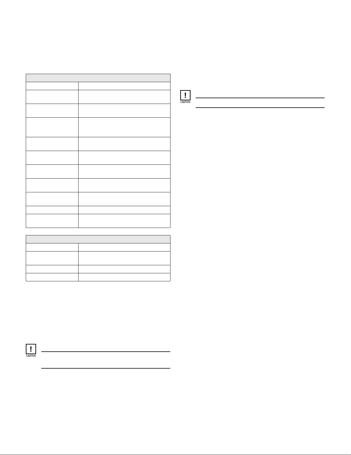
Table 4-4. End Play
Model Motor Size End Play (inches)
ALL ALL 0.072 to 0.096
(0.18 to 0.24 CM)
If the end play exceeds the maximum allowable movement, then
the bearings and/or thrust washers are worn and must be replaced.
(It should be noted that under proper operating conditions, wear
on these parts due to axial thrust forces will be negligible). It is
not necessary to check the end play with the pump casing
mounted on the pump.
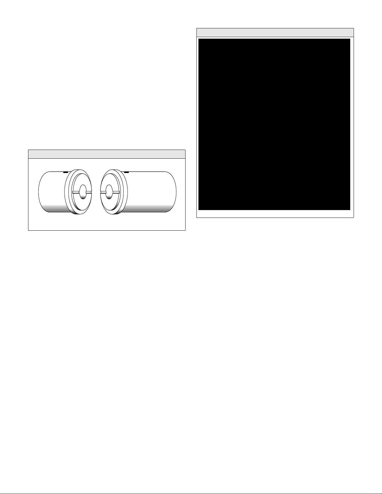
4.3.3 Rotor Assembly Inspection
The complete rotor assembly should be visually inspected for
cracks, breaks, pitting, or corrosion which might destroy the
effectiveness of the hermetically sealed rotor end covers and
sleeve.
Check the rotor assembly for straightness of the shaft. The shaft
should be running true and the sleeved rotor core within .003"
(.08 mm) of the shaft.
The rotor assembly shaft sleeves and thrust surfaces should also
be visually inspected at the bearing contact area for general
appearance and uniform wear. Excessive undercutting, pitting, or
scoring is cause for replacement.
4.3.4 Stator Assembly Inspection
The complete stator assembly should be visually inspected for
cracks, breaks, pitting, or corrosion in the stator liner which might
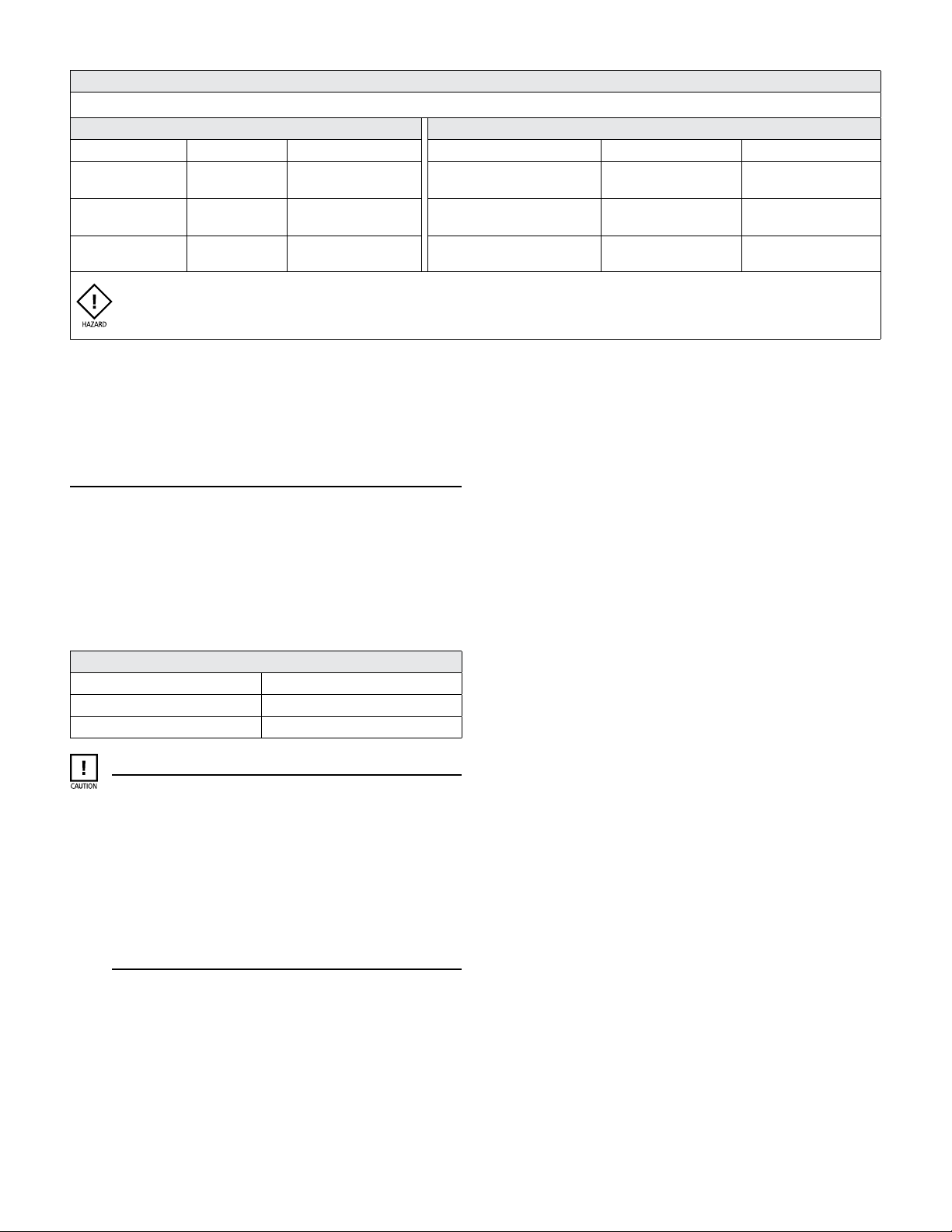
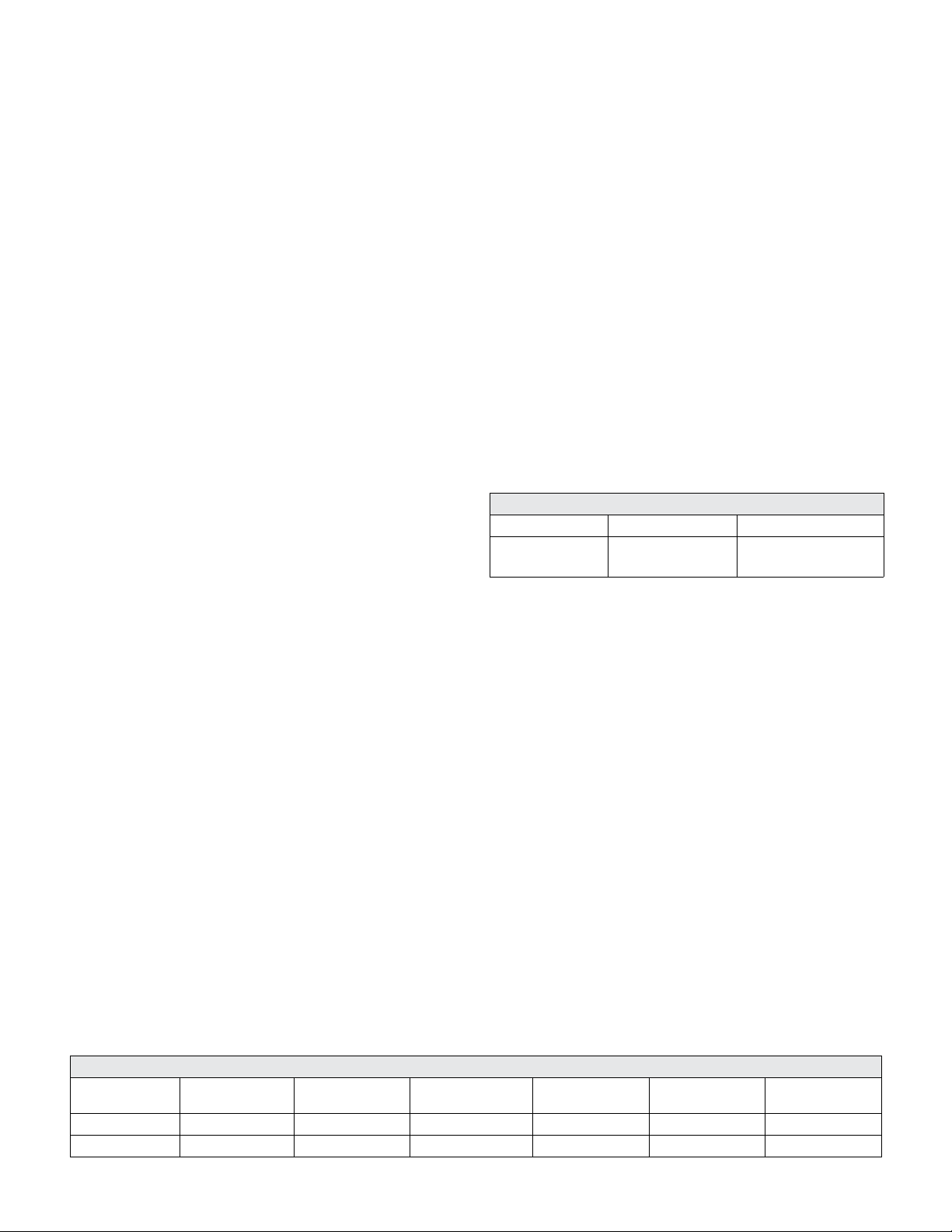
Table 4-3. NCT- Series Bearing and Journal Dimensions
Model Unit Shaft Sleeve
Bearing
Inside DIA
Diametrical
Clearance Max Allowable Length
ALL INCHES 1.6220 - 1.6213 1.626 - 1.627 0.004 - 0.0057 .014 3.0
ALL CM 6.38 6.4 0.02 0.005 11.8
This manual suits for next models
8
Table of contents
Other Teikoku Water Pump manuals
Popular Water Pump manuals by other brands

BRINKMANN PUMPS
BRINKMANN PUMPS SFT Series operating instructions

Pentair Jung Pumpen
Pentair Jung Pumpen Compli 1010/4 BWE instruction manual

Aquatop
Aquatop Breza owner's manual

Elpumps
Elpumps CT 2274 operating instructions

Pentair
Pentair STA-RITE DPC owner's manual

XP Aqua
XP Aqua Duetto ATO DATO-200P manual