Teikoku USA | Chempump Instruction Manual HE-12270 (1219)7
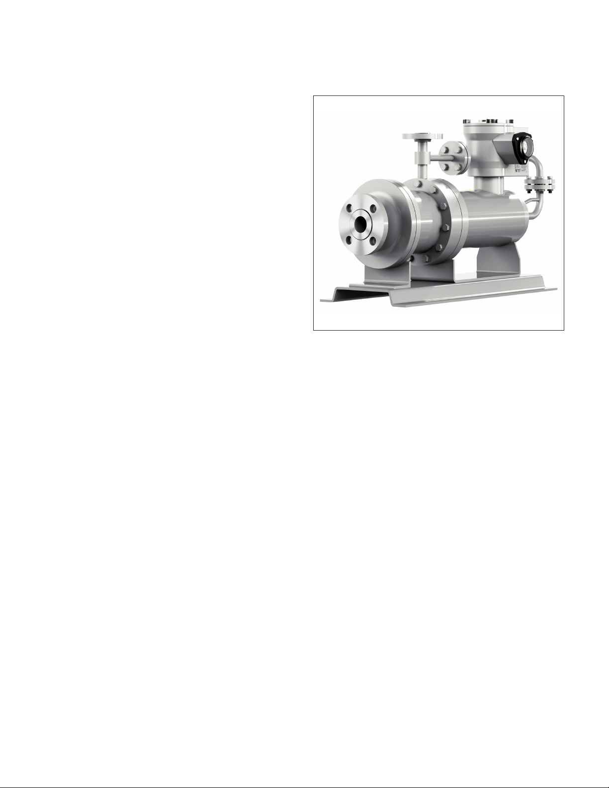
The Type-F (Plan 1-SD) pressurized circulation ALP multi-stage
pump is a precision built unit that with proper operation and
maintenance will provide years of trouble-free, leakproof ser-
vice. The entire unit is mounted on a fabricated steel base cradle.
Operation is unaffected by the mounting or operating position,
eliminating the need for any costly alignment procedures.
1.2 Stator Assembly
The stator assembly consists of a set of three-phase windings
designed for use with Pulse Width Modulated (PWM) Variable
Frequency Drive (VFD) power for 50 HZ to 120 HZ operation. Sta-
tor laminations are of low-silicon grade steel. Laminations and
windings are mounted inside the cylindrical stator band. End
bells, welded to the stator band, close off the ends of the stator
assembly. The stator liner is, in effect, a cylindrical can placed in
the stator bore and welded to the rear end bell and front end bell
to hermetically seal off the windings from contact with the liquid
being pumped.
Terminal leads from the windings are brought into an electrical
terminal box. Motor lead wires are isolated from the users’ con-
duit line by a leakproof terminal plate assembly mounted inside
the terminal box. The design of the stator assembly in conjunction
with the leakproof terminal plate assembly provides an advanced
low probabilty true positive secondary containment.
1.3 Rotor Assembly
The rotor assembly is a squirrel cage induction rotor constructed
and machined for use in the Type-F (Plan 1-SD) pressurized
circulation ALP multi-stage pump. It consists of a machined
corrosion-resistant shaft, laminated core with cast aluminum bars
and end rings, corrosion-resistant end covers, and a corrosion-
resistant can.
The rotor end covers are welded to the shaft and also to the
rotor can which surrounds the outside of the rotor, thus
hermetically sealing off the rotor core from contact with the liquid
being pumped.
The impellers are keyed to the shaft and held in place with a lock
bolt and lock washer. The shaft is fitted with replaceable shaft
sleeves and thrust collars. These parts are pinned or keyed to pre-
vent rotation. Axial movement is restricted by the thrust collars
contacting the face of the front and rear motor bearings.
1.4 Liquid Film Journal Bearings
The liquid film journal bearings for the Type-F (Plan 1-SD) pres-
surized circulation ALP multi-stage pump are carbon graphite as
standard and are machined with special helix grooves through
the bore to assure adequate liquid circulation at the journal area.
Each liquid film journal bearing is manufactured to close toler-
ances for a high degree of concentricity and is held in a bearing
housing by a retaining screw. Liquid film journal bearings are eas-
ily replaced by removing the retaining screw and sliding the bear-
ing from its housing.
1.5 Thrust Collars and Shaft Sleeves
All Type-F (Plan 1-SD) pressurized circulation ALP multi-stage
pump models are equipped with thrust collars, providing a re-
placeable surface against which axial loads can be carried during
process upset conditions. The shaft is also fitted with replaceable
shaft sleeves. Both the thrust collars and shaft sleeves are con-
structed of 316SS with a Stellite wear surface for long life. These
parts are pinned or keyed to prevent rotation.
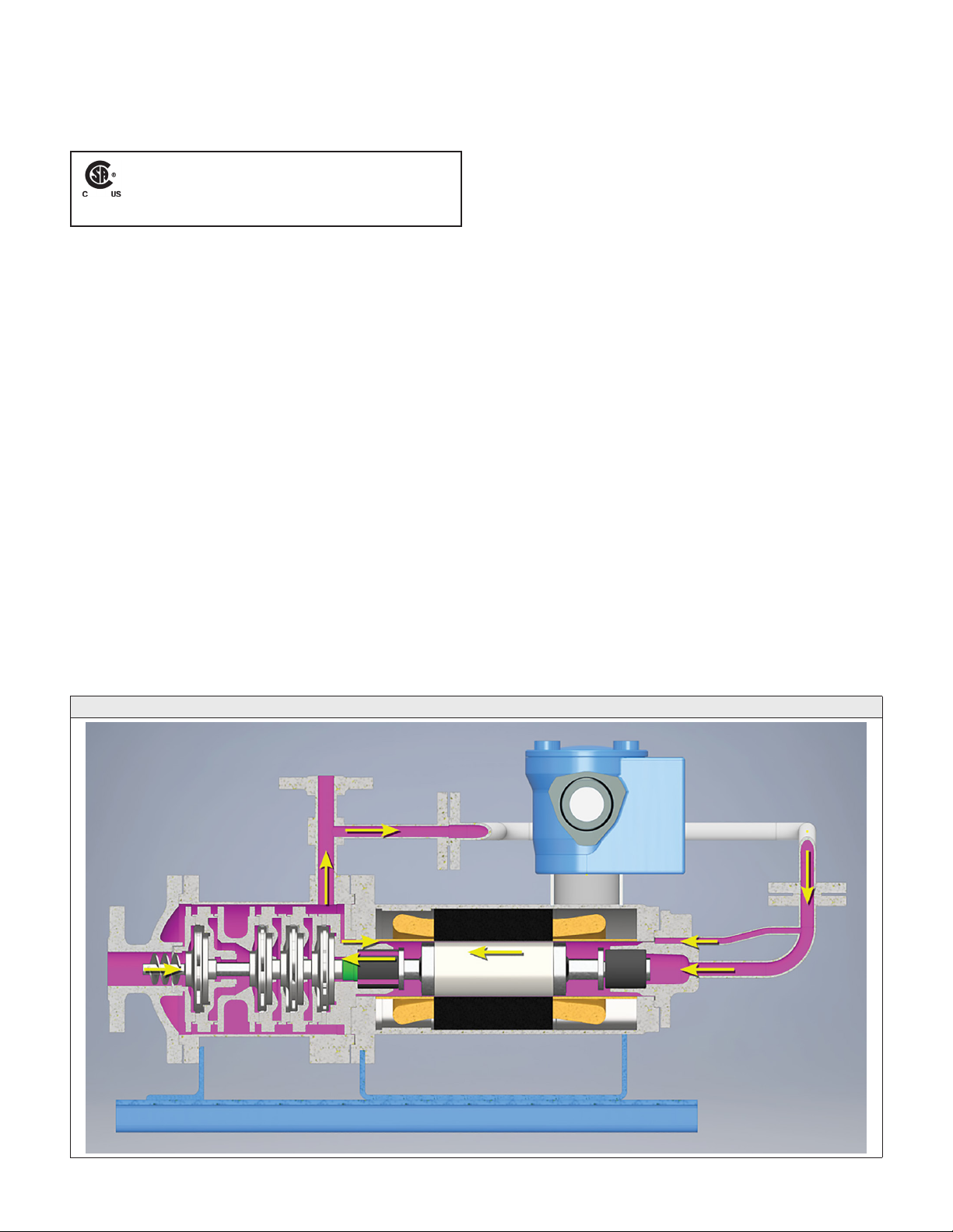
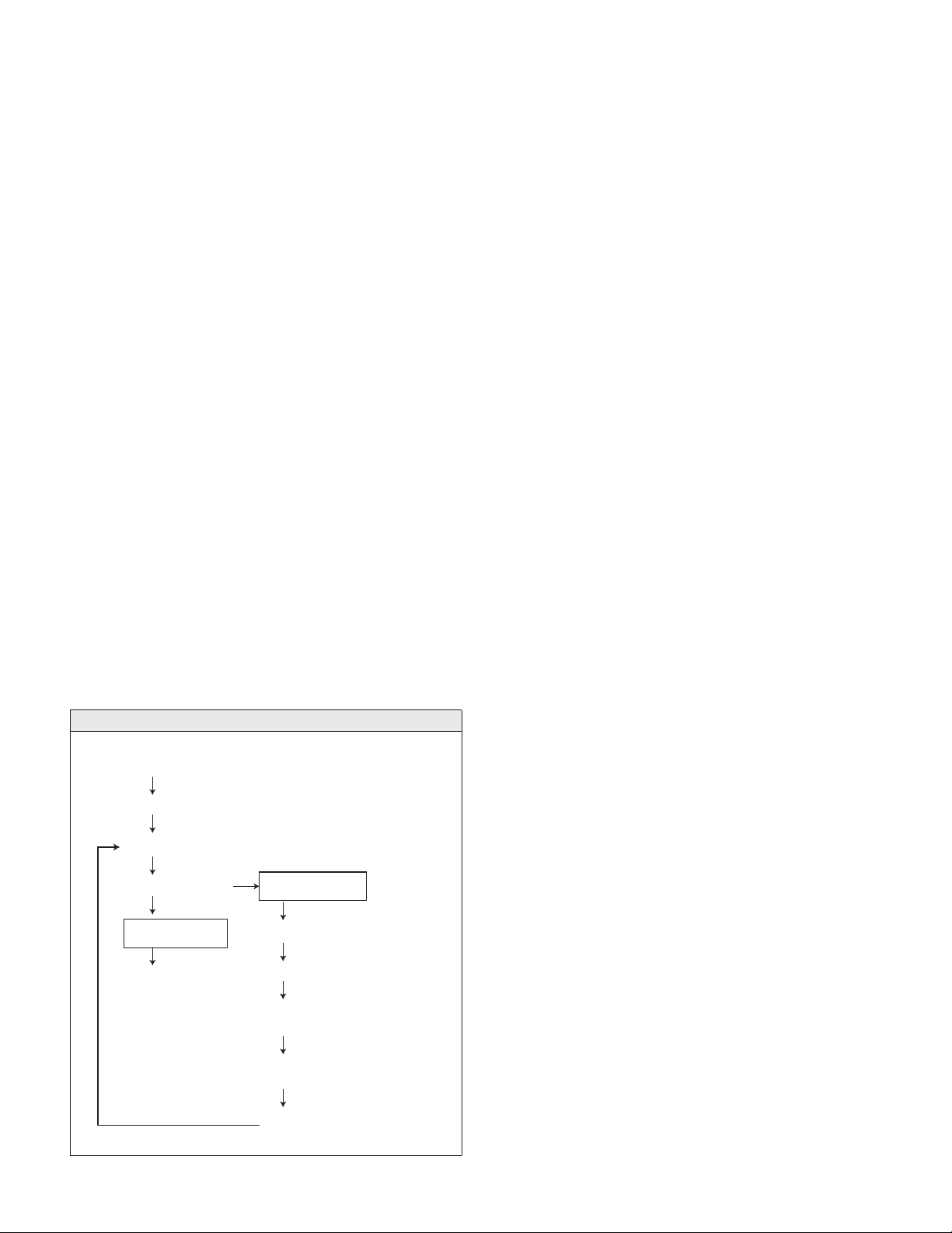
1.6 Internal Cooling Flow
Flow paths of the Type-F (Plan 1-SD) pressurized circulation ALP
multi-stage pumps are shown in Figure 1-1 and Figure 1-2. The
circulating liquid is channeled into the motor section by the cir-
culation pipe connected to the discharge flange. The circulating
liquid lubricates the rear liquid film journal bearing, passes over
the rotor core cooling the motor, lubricates the front liquid film
journal bearing and then returns to the main flow at the inlet of
the final stage impeller. The flow rate is controlled by a restriction
orifice mounted in the circulation pipe.
1.7 Automatic Thrust Balance
Based on hydraulic principles, Type-F (Plan 1-SD) pressurized circu-
lation ALP multi-stage pump automatic thrust balance is accom-
plished by the pressure of the pumped liquid itself, operating in a
balance chamber at the front and rear of the impeller.
When a change in load shifts the position of the impeller away
from the balance condition, there is an equalizing change of hy-
draulic pressure in the balance chamber, which immediately re-
turns the impeller-rotor assembly to the balanced position.
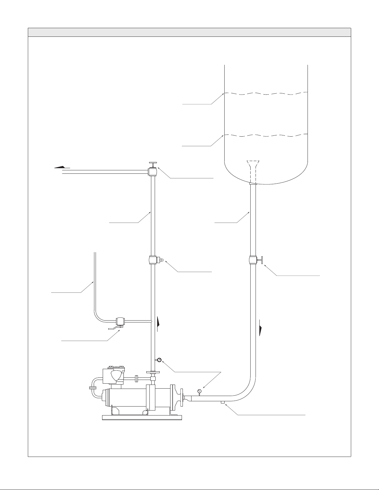
1.8 ALP Pump NH3Transfer System Requirements
Figure 1-3 shows a typical anhydrous ammonia transfer system
setup to support a Type-F (Plan 1-SD) pressurized circulation ALP
multi-stage pump for installation, commissioning and operation.
Figure 1-2. Flow Path
Casing Cover inlet
First Stage Impeller
Final Stage Impeller
Pipe Casing Outlet Circulation Flow
Circulation Pipe
Rear Bearing Housing
Gap between Rear Bearing
and Rear Shaft Sleeve
Gap between Stator Can
and Rotor Can
Gap between Front Bearing
and Front Shaft Sleeve
Main Flow
To the Process Line