TEK 2225 User manual

TEK
SERVICE
070-6299-00
MANUAL
Product
Group
46
OSCILLOSCOPE
SERVICE
THE FOLLOWING SERVICING INSTRUCTIONS ARE
FOR USE BY QUALIFIED PERSONNEL ONLY. TO
AVOID PERSONAL INJURY, DO NOT PERFORM ANY
SERVICING OTHER THAN THAT CONTAINED IN
OPERATING INSTRUCTIONS UNLESS YOU ARE
QUALIFIED TO DO SO. REFER TO OPERATORS
SAFETY SUMMARY AND SERVICE SAFETY SUM-
MARY PRIOR TO PERFORMING ANY SERVICE.
Please Check for
CHANGE
INFORMATION
at
the Rear of This Manual
First
Printing
OCT
1987
Revised
APR
1990
Scans
by
ARTEK
MEDL4
==-
Copyright
O
1987 Tektronix, Inc. All rights reserved. Contents of this
publication may not be reproduced in any form without the written
permission of Tektronix, Inc.
Products of Tektronix, Inc. and its subsidiaries are covered by W.S. and
foreign patents issued and pending.
TEKTRONIX, TEK, SCOPE-MOBILE, and are registered trade-
marks of Tektronix, Inc.
Printed in U.S.A. Specification and price change privileges are
reserved.
INSTRUMENT SERIAL NUMBERS
Each instrument has a serial number on a panel insert, tag, or
stamped on the chassis. The first number or letter designates the
country of manufacture. The last five digits of the serial number are
assigned sequentially and are unique to each instrument. Those manu-
factured in the United States have six unique digits. The country of
manufacture is identified as follows:
BOO0000 Tektronix, Inc., Beaverton, Oregon, U.S.A.
HKOOOOl Hong Kong
100000 Tektronix Guernsey, Ltd., Channel Islands
200000 Tektronix United Kingdom, Ltd., London
300000 SonyITektronix, Japan
700000 Tektronix Holland, NV, Heerenveen,
The Netherlands
Scam
by
ARTEK
MEDIA
3

2225
Service
TABLE
OF
CONTENTS
Page
LIST OF ILLUSTRATIONS
...................
iv
LIST OF TABLES
...........................
v
OPERATORS SAFETY SUMMARY
............
vi
SERVICING SAFETY SUMMARY
.............
vii
Section
1
SPECIFICATION
INTRODUCTION
..............
1-1
ACCESSORIES
..............
1-1
FOR MORE INFORMATION
.....
1-1
RECOMMENDED RECALIBRATION
.................
SCHEDULE 1-1
PERFORMANCE CONDITIONS
..
1-1
Section
2
OPERATING INSTRUCTIONS
PREPARATION FOR USE
........
2-1
SAFETY
....................
2-1
LINE VOLTAGE SELECTION
....
2-1
LINE FUSE
.................
2-2
POWER CORD
..............
2-2
INSTRUMENT COOLING
.......
2-2
INITIAL START-UP
...........
2-2
REPACKAGING
..............
2-3
CONTROLS. CONNECTORS.
AND INDICATORS
..............
2-4
POWER AlVD DISPLAY
........
2-4
VERTICAL
..................
2-4
HORIZONTAL
...............
2-5
Page
TRIGGER
..................
2-6
REAR PANEL
...............
2-7
OPERATING CONSIDERATIONS
. .
2-8
GRATICULE
................
2-8
GROUNDING
...............
2-8
SIGNAL CONNECTIONS
......
2-8
INPUT-COLIPLING
CAPACITOR PRECHARGING
...
2-9
OPERATOR'S CHECKS AND
ADJUSTMENTS
..............
2-10
INITIAL SETUP
.............
2-10
TRACE ROTATION
ADJUSTMENT
.............
2-10
PROBE COMPENSATION
.....
2-10
Section
3
THEORY OF OPERA'I'ION
SECTION ORGANIZATION
.....
3-1
INTEGRATED ClRClJlT
DESCRIPTIONS
.............
3-1
GENERAL DESCRIPTION
........
3-1
DETAILED CIRCUIT
DESCRIPTION
................
3-3
VERTICAL
.................
3-3
TRIGGER
..................
3-7
SWEEP AND SWEEP
GENERATOR LOGIC
........
3-10
HORIZONTAL
..............
3-12
FRONT PANEL
.............
3-14
Z-AXIS AMPLIFIER
.........
3-14
POWER SUPPLY
...........
3-16
Scam
by
ARTEK
MEDIA
=>
2225
Service
TABLE OF CONTENTS
(cont)
Page Page
Section
4
PERFORMANCE CHECK PROCEDLIRE Section
5
ADJUSTMENT PROCEDLIRE
INTRODUCTION
................
4-1
PERFORMANCE CHECK
..................
INTERVAL 4-1
STRUCTURE
................
4-1
TEST EQUIPMENT
REQUIRED
..................
4-1
LIMITS AND TOLERANCES
.....
4-1
PREPARATION FOR
CHECKS
...................
4-1
INDEX TO PERFORMANCE
CHECK STEPS
..............
4-3
VERTICAL
....................
4-4
INITIAL CONTROL
SETTINGS
..................
4-4
PROCEDURE STEPS
..........
4-4
HORIZONTAL
.................
4-8
INITIAL CONTROL
SETTINGS
..................
4-8
PROCEDURE STEPS
..........
4-8
TRIGGER
....................
4-12
INITIAL CONTROL
SETTINGS
.................
4-1 2
PROCEDURE STEPS
.........
4-1 2
EXTERNAL Z-AXIS AND
PROBE ADJUST
..............
4-1 5
INITIAL CONTROL
SETTINGS
.................
4-1
5
.........
PROCEDURE STEPS 4-1 5
INTRODUCTION
...............
5-1
..................
PURPOSE 5-1
...............
STRUCTURE 5-1
TEST EQUIPMENT
REQUIRED
.................
5-1
LIMITS AND TOLERANCES
....
5-1
ADJUSTMENTS AFFECTED
BY
REPAIRS
..................
5-1
PREPARATION FOR
ADJUSTMENT
..............
5-1
INDEX TO ADJUSTMENT
PROCEDURE STEPS
.........
5-3
POWER SLIPPLY AND
................
CRT DISPLAY 5-4
INITIAL CONTROL
SETTINGS
.................
5-4
PROCEDURE STEPS
.........
5-4
VERTICAL
...................
5-6
INITIAL CONTROL
SETTINGS
.................
5-6
PROCEDURE STEPS
.........
5-6
HORIZONTAL
................
5-13
INITIAL CONTROL
SETTINGS
................
5-13
........
PROCEDURE STEPS 5-13
TRIGGER
...................
5-18
INITIAL CONTROL
SETTINGS
................
5-18
PROCEDURE STEPS
........
5-18
EXTERNAL Z-AXIS AND
.............
PROBE ADJUST 5-22
INITIAL CONTROL
................
SETTINGS 5-22
........
PROCEDURE STEPS 5-22
Scam
by
ARTEK
MEDL4
*
2225
Service
TABLE OF CONTENTS
(cont)
Page
Section
6
MAINTENANCE
STATIC-SENSITIVE
COMPONENTS
.
.
..
.
..
.
...
..
.
..
6-1
PREVENTIVE MAINTENANCE
....
.
6-2
INTRODUCTION
..
.
..
.
.
.
..
.
.
.
.
6-2
GENERAL CARE
..
..
..
.
.
.
.
.
.
.
6-2
INSPECTION AND
CLEANING
.
.
..
..
.
..
.
.
.
.
....
.
6-2
Page
OBTAINING REPLACEMENT
PARTS
.
.
.
..
.
..
.
..
.
.
..
..
..
6-1
0
MAINTENANCE AlDS
.
......
6-1
1
INTERCONNECTIONS
..
..
.
..
6-1
1
TRANSISTORS AND
INTEGRATED CIRCUITS
.
.
.
..
6-1 1
SOLDERING TECHNIQLIES
...
6-12
REMOVAL AND REPLACE-
MENT INSTRUCTIONS
...
.
.
..
6-1
3
LUBRICATION
.
..
.
.
...
.
..
.
.
.
.
6-4
SEMICoNDUCToR
CHECKS
...
.
6-4
Section
7
OPTIONS AND ACCESSORIES
PERIODIC READJUSTMENT
.
.
.
.
6-4
TROUBLESHOOTING
.
.
..
.
.
.
.
.
..
.
6-4
INTRODUCTION
..
.
.
.
.
.
...
..
.
.
6-4
TROLIBLESHOOTING AlDS
.
..
..
6-4
INTRODUCTION
.
.
..
.
.
..
.
..
.
.
7-1
STANDARD ACCESSORIES
.
.
.
7-1
OPTIONS
.
..
.
.
..
..
.
.
.
.....
.
7-1
RIBBON-CABLE
CONNECTORS
.
..
.
..
..
.
.
.
..
.
6-6
TROUBLESHOOTING
Section
8
REPLACEABLE ELECTRICAL PARTS
EQUIPMENT
.
..
.
.
..
.
.
.
.
.
.
..
.
.
6-6
TROLIBLESHOOTING
Section
9
DIAGRAMS
TECHN~QL~ES
,
.
.
.
..
.
..
,,
.
.
.
6-7
Section
10
REPLACEABLE MECHANICAL PARTS
CORRECTIVE MAINTENANCE
...
6-10
INTRODUCTION
.
.
..
.
..
...
.
.
.
6-1
0
APPENDIX
MAINTENANCE
PRECAUTIONS
.
.
.
..
.
..
.
.
..
.
6-10
CHANGE INFORMATION
iii
Scam
by
ARTEK
MEDIA
=>

2225
Service
Figure
LIST
OF
ILLUSTRATIONS
Page
The 2225 Oscilloscope
..............................................................
viii
........................................
1-1 Max Input Voltage Vs Frequency Derating Curve 1-7
......................................................
1-2 Instrument dimensional drawing 1-8
...............................
2-1 Voltage Selector switch. fuse. and power-cord receptacle 2-1
....................................................
2-2 Power-cord and line-voltage data 2-2
2-3 Rear Panel
.......................................................................
2-7
.....................................................
2-4 Graticule measurement markings 2-8
2-5 Probe compensation
..............................................................
2-11
......................................................
2-6 Probe compensation locations 2-11
......................................
3-1 Block diagram of the Channel 1 Attenuator circuit 3-3
.........................................
3-2 Block diagram of the Channel Switching circuit 3-5
................................
3-3 Block diagram of the Sweep Generator and Logic circuit 3-10
.......................................
3-4 Block diagram of the Horizontal Amplifier circuit 3-13
3-5 Simplified diagram of the DC Restorer circuitry
........................................
3-15
5-1 Attenuator trimmer adjustments
......................................................
5-9
6-1 Multi-connector operation
...........................................................
6-6
Scam
by
ARTEK
MEDIA
*


2225
Service
OPERATORS SAFETY SUMMARY
The safety information in this summary is for operafing personnel. Warnings and cautions will also
be
found
throughout the manual where they apply.
Terms in this Manual Grounding the Product
CAUTION statements identify conditions or practices This product is grounded through the groundingcon-
that could result in damage to the equipment or ductor of the power cord. TOavoid electrical shock,
other property. plug the power cord into a properly wired recepta-
cle before making any connections to the product
WARNING statements identify conditions or practices input or output terminals. A protective ground con-
that could result in personal injury or loss of life. nection, by way of the grounding conductor in the
power cord, is essential for safe operation.
Terms as Marked on Equipment Danger Arising From Loss of Ground
CAUTION indicates a personal injury hazard not im-
Upon
loss
of
the
protective-ground connection,
all
mediately accessible as one reads the markings, or
accessible
conductive
parts,
including
knobs
and
a
hazard
property, including
the
itself' controls that may appear to be insulating, can ,-en-
DANGER indicates
a
personal injury hazard immedi- der an electric shock.
ately accessible as one reads the marking.
Use the Proper Power Cord
Symbols in this Manual
Use only the power cord and connector specified for
your product.
This symbol indicates where applicable
cautionary or other information is to Use only a power cord that is in good condition.
be found. For maximum input voltage
see Table
1-1
.
For detailed information on power cords and con-
nectors, see Figure
2-2.
Symbols as Marked on Equipment Use the Proper Fuse
1
DANGER-High voltage.
@
Protective ground (earth) terminal.
A
ATTENTION-Refer to manual.
Power Source
To avoid fire hazard, use only a fuse of the correct
type, voltage rating and current rating as specified in
the parts list for your product.
Do Not Operate in an Explosive
To avoid explosion, do not operate this instrument in
an explosive atmosphere unless it has been specifi-
cally certified for such operation.
This product is intended to operate from a power
source that does not apply more than
250
V
rms
DO Not Remove Covers or Panels
between the supply conductors or between either
supply conductor and ground. A protective ground To avoid personal injury, do not remove the product
connection, by way of the grounding conductor in covers or panels. Do not operate the product with-
the power cord, is essential for safe operation. out the covers and panels properly installed.
Scans
by
ARTEK
MEDU
=>

2225
Service
SERVICING SAFETY SUMMARY
FOR QUALIFIED SERVICE PERSONNEL ONLY
Refer also to the preceding Operators Safety Summary
Do Not Service Alone
Disconnect power before removing protective
panels, soldering, or replacing components.
Do not perform internal service or adjustment of this
product unless another person capable of rendering
first aid and resuscitation is present.
Power Source
Use Care When Servicing With Power On
This product is intended to operate from a power
source that does not apply more than
250
volts rms
Dangerous voltages exist at several points in this between the supply conductors or between either
product. To avoid personal injury, do not touch ex- supply conductor and ground.
A
protective ground
posed connections or components while power is connection by way of the grounding connetor in the
on. power cord is essential for safe operation.
Scam
by
ARTEK
MEN
=>

Section
1-2225
Service
SPECIFICATION
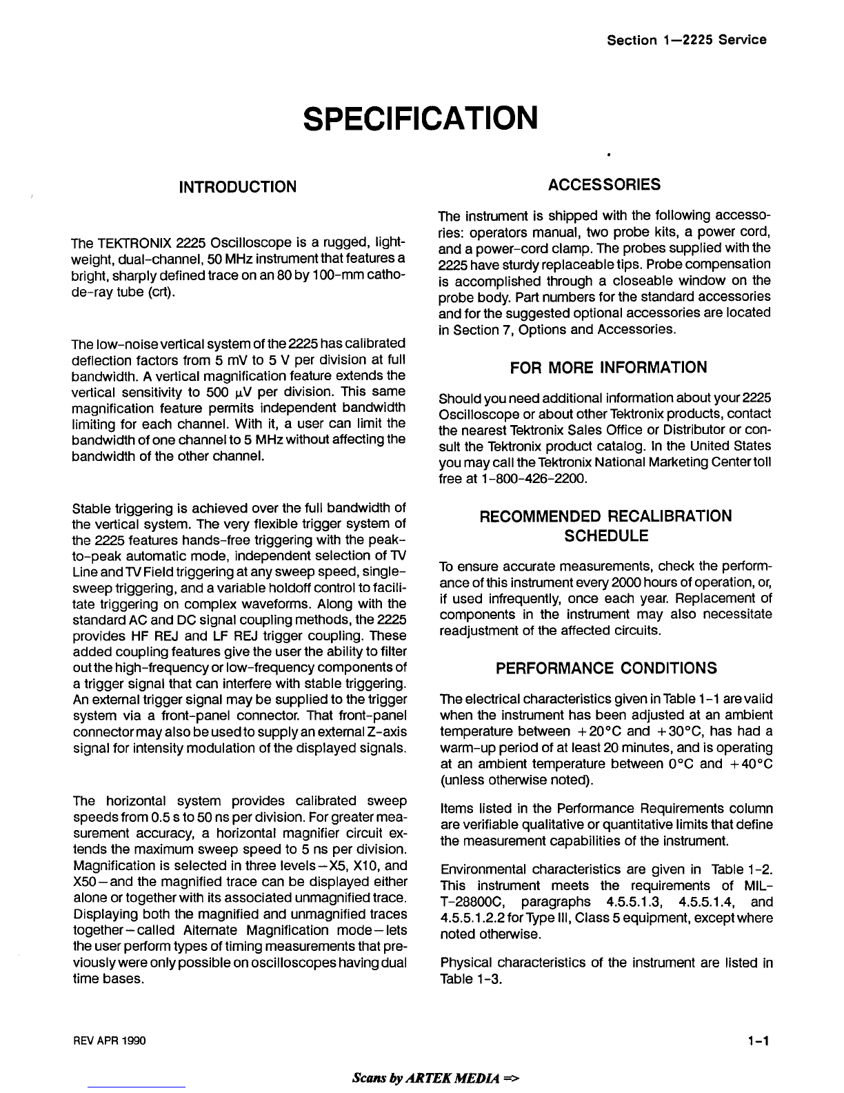
INTRODUCTION ACCESSORIES
The instrument is shipped with the following accesso-
ries: operators manual, two probe kits, a power cord,
The
TEKTRoNIX
2225
oscillosco~e
is
a
light- and a power-cord clamp.The probessuppliedwiththe
weight,dual-channel, 50MHz instrumentthat featuresa 2225
have
sturdy
replaceable
tips.
Probe
compensation
bright*
defined
trace
On
an
80
100-mm
is
accomplishedthrough a closeable window on the
de-ray tube (crt). probebody. Part numbersfor the standard accessories
andfor the suggestedoptionalaccessoriesare located
inSection
7,
Options and Accessories.
The low-noisevertical systemofthe2225hascalibrated
deflectionfactors from
5
mV to 5 V per division at full
bandwidth.A vertical ma~nificationfeature extendsthe
FOR MORE INFORMATION
vertical sensitivity to 506 FV per division. This same
Should
you
need
additional
infonation
about
your
2225
magnification
feature
permits independent
bandwidth
Oscilloscopeor about other TeMronixproducts,contact
limitingfor each channel. With it, a user can limit the
the
nearest
Tektronix
Sales
Office
or
Distributor
or
con-
bandwid'h ofone channel
'0
5 MHzwi'hout affectingthe
suit
the TeMronixproduct catalog.
in
fie
UnitedStates
bandwidth of the other channel. youmaycalltheTektronixNationalMarketingCentertoll
free at 1-800-426-2200.
Stabletriggering isachieved over thefull bandwidthof
the vertical system. The very flexibletrigger system of
the 2225 features hands-free triggering with the peak-
to-peak automatic mode, independentselectionof TV
LineandTVFieldtriggeringat anysweep speed,single-
sweeptriggering, and avariableholdoff controltofacili-
tate triggering on complex waveforms. Along with the
standardAC and DC signal couplingmethods,the2225
provides HF REJ and LF REJ trigger coupling. These
addedcouplingfeatures givethe userthe abilityto filter
outthehigh-frequency or low-frequency componentsof
a trigger signal that can interferewith stable triggering.
An externaltrigger signal may besuppliedto thetrigger
system via a front-panel connector. That front-panel
connectormayalsobeusedto supplyanexternalZ-axis
signalfor intensitymodulationof the displayedsignals.
RECOMMENDED RECALIBRATION
SCHEDULE
To ensure accurate measurements,check the perform-
anceofthis instrument every2000hoursof operation,or,
if used infrequently, once each year. Replacement of
components in the instrument may also necessitate
readjustmentof the affected circuits.
PERFORMANCE CONDITIONS
The electricalcharacteristicsgiveninTable 1-1 arevalid
when the instrument has been adjustedat an ambient
temperature between +20°C and +30°C, has had a
warm-up periodof at least20 minutes, and isoperating
at an ambient temperature between O°C and +40°C
(unless otherwise noted).
The
horizontal
'ystem provides
calibrated
sweep Items listed in the Performance Requirements column
'peeds
from
0'5
to
50
ns
per
division'
For
greatermea- a, verifiablequalitativeor quantitativelimitsthat define
surement accuracy, a horizontal magnifier circuit ex-
tends the maximum sweep speedto 5 ns per division. the measurement capabilitiesof the instrument.
Magnification is selectedinthree levels-X5, XlO, and Environmental characteristics are given in Table 1-2.
X50-and the magnifiedtrace can be displayed either This instrument meets the requirements of
MIL-
alone or togetherwithitsassociatedunmagnifiedtrace. ~-28800~,paragraphs 4.5.5.1.3, 4.5.5.1-4, and
Displayingboth the magnifiedand unmagnifiedtraces 4.5.5.1.2.2 forType Ill, Class5equipment, exceptwhere
together
-
called Alternate Magnification mode- lets notedotherwise.
theuserperformtypesoftimingmeasurementsthat pre-
viouslywereonlypossibleonoscilloscopeshavingdual Physical characteristics of the instrument are listed in
time bases. Table 1-3.
RN
APR
1990
Scam
by
ARTEK
MEDIA
==-
Specification-2225 Service
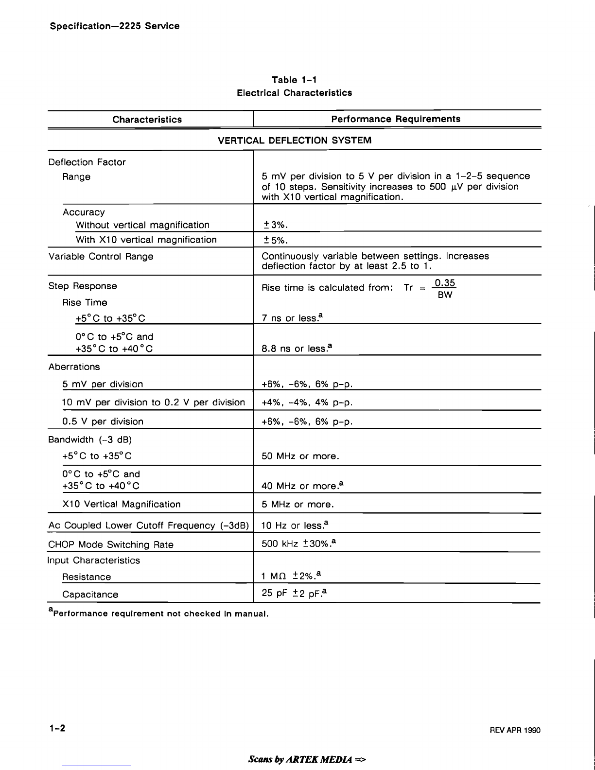
Table
1-1
Electrical Characteristics
VERTICAL DEFLECTION SYSTEM
Characteristics Performance Requirements
a
Performance requirement not checked in manual.
Deflection Factor
Range
Accuracy
Without vertical magnification
With XI0 vertical magnification
Variable Control Range
Step Response
Rise Time
+5" C to +35"C
0°C to +5"C and
+35OC to +40°C
Aberrations
5
mV per division
10 mV per division to 0.2 V per division
0.5 V per division
Bandwidth (-3 dB)
+5OC to +35OC
0°C to +5OC and
+35' C to +40°C
XI0 Vertical Magnification
Ac Coupled Lower Cutoff Frequency (-3dB)
CHOP Mode Switching Rate
Input Characteristics
Resistance
Capacitance
Scans
by
ARTEK
MEDLQ
=>
5 mV per division to 5 V per division in a 1-2-5 sequence
of 10 steps. Sensitivity increases to 500 pV per division
with XI0 vertical magnification.
2
3%.
2
5%.
Continuously variable between settings. Increases
deflection factor by at least 2.5 to 1.
Rise time is calculated from: Tr
=
-
0 35
BW
7
ns or lessa
8.8
ns or lessa
+6%, -6%, 6% p-p.
+4%, -4%, 4% p-p.
+6%, -6%,
6%
p-p.
50 MHz or more.
40 MHz or more.a
5 MHz or more.
10 Hz or lessa
500
kHz
?30%.a
1 Mi2 ?2%.a
25 pF +2 pFa
REV
APR
1990

Specification-2225 Service
Table
1-1
(cont)
Characteristics
With XI0 Vertical Magnification
I
At least 10 to 1 at 1 MHz.
Performance Requirements
Maximum Safe Input Voltage
(DC or AC Coupled)
Common-mode Rejection Ratio(CMRR)
Without Vertical Maanification
Trace Shift with VOLTSIDIV
Switch Rotation
400 V (dc
+
peak ac) or 800 V ac p-p at 10 kHz or lessa
(See Figure 1-1 for frequency derating curve.)
At least 10 to 1 at 10 MHz.
0.75 division or less; VOLTS/DIV Variable control
in the CAL detent?
Trace Shift as the VOLTSIDIV Variable
Control is rotated.
Trace Shift with CH 2 INVERT
Position Control Range
1 division or lessa
1.5 division or lessa
Trace Shift with XI0 Vertical Magnification
Channel Isolation
10.5 divisions above and below the center graticule
I
line at 25OC with the cabinet installed.
2.0 divisions or less?
Greater than 100:l at 10 MHz.
Trace Separation Range
I
At least
23
divisions.
TRIGGERING
Trigger Sensitivity
P-P AUTOITV LINE and
NORM Modes
5
MHz
I
50 MHz
I
TV FIELD
I
1
division of composite synca
I
I
Internal Signal
External Signal
External Input
I
0.3
div
40 mV
Lowest Usable Frequency in
P-P AUTO Mode
1.0 div
200 mV
A 1.0 division internal signal or 100 mV external signal
of 20 Hz or higher frequency will trigger.
Input Capacitance
1
25 PF 22.5
PFP
I
I
Input Resistance 1
Ma
Maximum Input Voltage
AC Coupled Lower Cutoff
Frequency (-3dB)
Scam
by
ARTEK
MEDL4
=>
I
400 V (dc
+
peak ac) or 800 V ac p-p at 10 kHz or lessa
(See Figure 1-1 for frequency derating curve.)
i
Internal Signal
External Signal 10 Hz or less?
20 Hz or less.a
a
Performance requlrement not checked
in
manual.

Specification-2225 Service
Table
1-1
(cont)
Characteristics
Trigger Level Range
NORM Mode
EXT Source
EXTI10 Source
Variable Holdoff Range
LF REJ Lower 3 dB point
HF REJ 3 dB point
Performance Requirements
Level may be set to any point of trace that can be
displayed.
At least 21.2 V, 2.4 V p-p.
At least 212 V, 24 V p-p.
Increases sweep holdoff time by at least a factor
of
8
at maximum holdoff?
30 kHz ?25%.a
30 kHz 225%.a
HORIZONTAL DEFLECTION SYSTEM
Sweep accuracy applies over the center eight divisions.
Exclude the first 25 ns of the sweep for magnified sweep
speeds and anything beyond the 100th magnified division.
Sweep Rates
Calibrated Range
Sweep
Accuracy
SECIDIV Variable Range
0.5 s per division to 0.05 ~s per division in a 1-2-5
sequence of 22 steps. The XI0 magnifier extends
maximum sweep speed to 5 ns per di~ision.~
Continuously variable and uncalibrated between calibrated
step settings of the SECIDIV switch. Decreases calibrated
sweep speeds by at least a factor of 2.5.
Unmagnified
X1
Magnified
X5 XI0 X50
Sweep Linearity
POSITION Control Range
Unmasnified
XI
Start of sweep to 10th division in XI, to 50th division
in X5, to 100th in X10, and to 500 division in X50 will
position past the center vertical graticule line.
Registration between Magnified and
Unmagnified traces
a
Performance requirement not checked in manual.
Magnified
X5 XI0 X50
0.2 division or less (measuredwhen switching from Magnifiedto
Unmagnified),alignedto center vertical graticule 1ine.a
Trace Shift between ALT and MAG
Modes
Scans
by
ARTEK
MEDIA
=>
Less than 1 divisiona
REV
APR
1990

Specification-2225 Service
Table 1-1 (cont)
Characteristics
X-Y OPERATION (XI MODE)
Performance Requirements
Sensitivity
Usable frequency range
Maximum Safe Input Voltage
Z-AXIS
5 V causes noticeable modulation. Positive-going
input decreases intensity.
DC
to 5
MHZP
400 V (dc
+
peak ac) or 800 V p-p ac at 10 kHz or less.a
(See Figure 1-1 for frequency derating curve.)
PROBE ADJUST SIGNAL OUTPUT
Deflection Factors
Accuracy
X- Axis
Y-Axis
Bandwidth (-3 dB)
X-Axis
Y-Axis
Phase difference between X-Axis and
Y-Axis Amplifiers
Same as vertical deflection system with variable controls
in the CAL detent.a
+
5%.
Same as vertical deflection systema
Dc to at least 2 MHz.
Same as vertical deflection systema
+3O from dc to 150 kHz with
DC
input coup1ing.a
POWER SUPPLY
Voltage into 1 MR Load
Repetition Rate
0.5 V +5%.
1 kHz -+5%.a
CATHODE-RAY TUBE
Line Voltage Ranges
115 V Setting
230 V Setting
Line Frequency
Maximum Power Consumption
Line Fuse
115 Setting
230 Setting
Nominal Accelerating Voltage
1
12,600
V
+60 V.a
a~erformancerequirement not checked
in
manual.
95 Vac to 128 Vaca
185 Vac to 250 Vacaa
48 Hz to 440
HZ.~
70 watts (80 VA)
.a
Display Area
Standard Phosphor
REV
APR
1990
UL 198.6 3AG
(1
I4 X 1 1/4 inch)
1.0 A, Slow.
0.5 A, Slow.
8
X
10 cma
GH (P31
)
.a
IEC127 (5
x
20 mm)
0.8 A, Slow.
0.4 A, Slow.

Specification-2225 Service
Table 1-2
Environmental Characteristics
a
Performance requirement not checked in
manual.
Characteristics
Temperature
Operating
Nonoperating
Altitude
Operating
Nonoperating
Relative Humidity
Operating (+30°C to +40°C)
Nonoperating (+30°C to +60°C)
Vibration
Operating
Shock
Operating and Nonoperating
Radiated and conducted
emission requirements
Scans
by
ARTEK
MEDLQ
=>
Performance Requirements
0°C to +40°C
(+32"F to +104"F)?
-55°C to t75"C
(-67"
F to +I67
"
F)
.a
To 4,570 meters (15,000 feet). Maximum operating
temperature decreased 1°C per 300 m (1000 feet)
above 1500 m (5,000 feet)
.a
To 15,250 meters (50,000 feet)
.a
5
cycles (120 hours) referenced to MIL-T-28800C para
4.5.5.1.2.2 for type Ill, Class 5 instruments. Operating and
nonoperating at 95% -5% to +0% relatiave humidity.
15 minutes along each of three major axes at a total
displacement of 0.015 inch p-p (2.4 g at 55 Hz) with
frequency varied from 10 Hz to 55
Hz
to 10 Hz in one
minute sweeps. Hold for 10 minutes at 55 Hz in each
of three major axes. All major resonances must be
above 55 Hz.a
30 g, half-sine, 11-ms duration, three shocks per axis
each direction, for a total of 18 shocks.=
Meets VDE 0871, Class
B
and FCC Docket 20870,
part 15, subpart
J
.a
REV
APR
1990

Specification-2225 Service
Table 1-3
Physical Characteristics
400
300
200
-
0
u
Y
4
w
100
a
+
0
0
-
m
50
I-
-I
0
>
20
10 10 kHz 50 kHz 100 kHz 500 kHz
I
MHz 50 MHz
6299-21
Characteristics
Weight
With Power Cord
Domestic Shipping Weight
Height
Width
With Handle
Without Handle
Depth
Without Front Cover
With Handle Extended
Figure 1-1. Max Input Voltage Vs Frequency Derating Curve.
Description
6.9 kg (15.2 Ibs) or less.
9.0 kg (19.8 Ibs) or less.
138 mm (5.42 in). (See Figure
1-2
for a dimensional
drawing).
385 rnm (15.2 in).
327 mm (12.9 in).
443 mm (17.3 in).
511 mm (20.1 in).
Scam
by
ARTEK
MEDIA
=>

Specification-2225 Service
Figure
1-2.
Instrument dimensional drawing.

Section 2-2225 Service
OPERATING INSTRUCTIONS
This section is divided into four subsections. The controls. Subsection three, Operating Consider-
first subsection, Preparation for Use, provides in- ations, provides the user with some of the more
structions for the user to follow before turning the general information on measurement techniques.
instrument on, especially for the first time. Sub- The last subsection, Operators Checks and
section two; Controls, Connectors, and Indicators; Adjustments, provides simple checks and adjust-
provides details on the operation of the front-panel ments to be made on a routine basis by the user.
PREPARATION
FOR
USE
SAFETY
This subsection tells how to prepare for and to pro-
ceed with the initial start-up of the TEKTRONIX 2225
Oscilloscope.
Refer to the Safety Summary at the front of this
manual for power source, grounding, and other
safety considerations pertaining to the use of the in-
strument. Before connecting the oscilloscope to a
power source, read both this subsection and the
Safety Summary.
This instrument may be damaged ifoperated
with the LlNE VOLTAGE SELECTOR switch
(on the rearpanel) set for the wrong applied
ac source voltage or if the wrong fuse is
installed.
LINE (MAINS) POWER-CORD
FUSE RECEPTACLE
REPLACING
FUSE
SELECTOR (MAINS) ATTACH POWER-
SWITCH CORD CLAMP
6299-23
LlNE VOLTAGE SELECTION
Figure 2-1. Voltage Selector switch, fuse, and
power-cord receptacle.
The oscilloscope operates from either a 115-V or a
230-V nominal ac power line with any frequency
from
48
Hz
to
440
Hz.
Before connecting the power
cord to a power source, verify that the LlNE
VOLTAGE SELECTOR switch, located on the rear
panel, is set correctly and that the proper line fuse is
installed. Referto Figure 2-1 and the instrument rear
panel.
To convert the 2225 for operation on another line
voltage range, set the LlNE VOLTAGE SELECTOR
switch to the required position and install the appro-
priate fuse (listed on the rear panel). The detach-
able power cord may need to be replaced to match
the particular power source. Power-cord option
numbers are given in Figure 2-1
;
fuse part numbers
are listed in Options and Accessories (Section
7).
Scans
by
ARTEK
MEDLQ
=>

Operating Instructions-2225 Service
LlNE FUSE
The instrument fuse holder is located on the rear
panel and contains the line (main) fuse. Use the
following procedure to verify that the proper fuse is
installed or to install a replacement fuse.
1.
Unplug the power cord from the power-input
source (if plugged in).
2. Press in the fuse-holder cap and release it with
a slight counterclockwise rotation.
3.
Pull the cap (with the attached fuse inside) out
of the fuse holder.
NOTE
The two types of fuses listed on the rear
panel are not directly interchangeable; they
require different types of fuse caps.
4.
Verify that the fuse is the same type listed on
the back of the instrument.
5.
Reinstall the fuse (or replacement fuse) in the
fuse-holder cap.
6.
Reinstall the fuse and cap in the fuse holder by
pressingin and giving a slight clockwise rotation
of the cap.
POWER CORD
A detachable three-wire power cord with a three-
contact plug is provided with each instrument for
connecting to both the power source and protective
ground. The protective-ground connector in the
plug connects (through the protective-ground con-
ductor) to the accessible metal parts of the instru-
ment. For electrical-shock protection, insert this
plug only into a power-source outlet that has a
properly grounded protective-ground contact.
Un~versal
%\
1
2r
1
240v
1
CEEIEC 83F'Lll,lV.Vll
1
;;
1
10-16A
8s 1363
240v'
"''
IEC 83
13A
Option
Number
Z
Reference
Standards
Line
Voltage
Plug
Configuration
North
ran
120v/
15A
North
Amerncan
240V/
15A
Abbreviations:
ANSl
-
American National Standards Institute
AS
-
Standards Association of Australia
BS
-
British Standards Institution
CEE
-
International Commiss~onon Rules for the
Approval of Electrical Equ~pment
IEC
-
International Electrotechnical Comm~ssion
NEMA
-
National Electrical Manufacturer's Association
(2931-21
)6083-35
Usage
Sw~tzerland
220V/
6A
Figure 2-2. Power-cord and line-voltage data.
120~
240V
INSTRUMENT COOLING
220V
To prevent instrument damage from overheated
components, adequate internal airflow must be
maintained at all times. Beforeturning on the power,
verify that the air-intake holes on the sides and rear
panel are free from any obstructions to airflow.
ANSI C73 11
5.15.~
IEC 83
ANSl C73 20
NEMA 6-15 P
IEC 83
INITIAL START-UP
Standard
A4
SEV
Up to now, you should have made the following
preparations:
A5
1.
Read the safety information.
After plugging the power cord into its receptacle,
2.
Verified that the LlNE VOLTAGE SELECTOR
secure it to the rear panel using the plastic clamp, switch is set for the source voltage to be used.
screw, and washer provided.
3.
Verified the fuse for correct type and rating.
Instruments are shipped with the power cord
ordered by the customer. Available power-cord
4.
Attached the power cord.
information
is
presented in Figure 2-2. Contact your
Tektronix representative or local Tektronix Field
5.
Ensured that there is adequate ventilation
Office for additional power-cord information. around the instrument.
Scans
by
ARTEK
MEDCQ
=>
Table of contents


