Saluki S2108 Series User manual

Optical Network Tester
User Manual

PREFACE
Thank you very much for buying and using S2108 series optical network tester. This manual mainly contains
the commonly used operating safety instructions, basic interface and operation introduction, as well as common
troubleshooting guidelines and other information. In order to facilitate your use, before operating this
instrument, please read the contents of this manual carefully and follow the instructions in the book correctly.
This manual is limited to use in conjunction with this instrument. No unit or individual may alter, copy or
disseminate the contents of this manual for commercial purposes without the authorization of the Company.
The contents of this manual are subject to change without prior notice. If you have any questions, please
call the supplier. We will do our best to provide you with the best service.

Ove
r
ew
vi
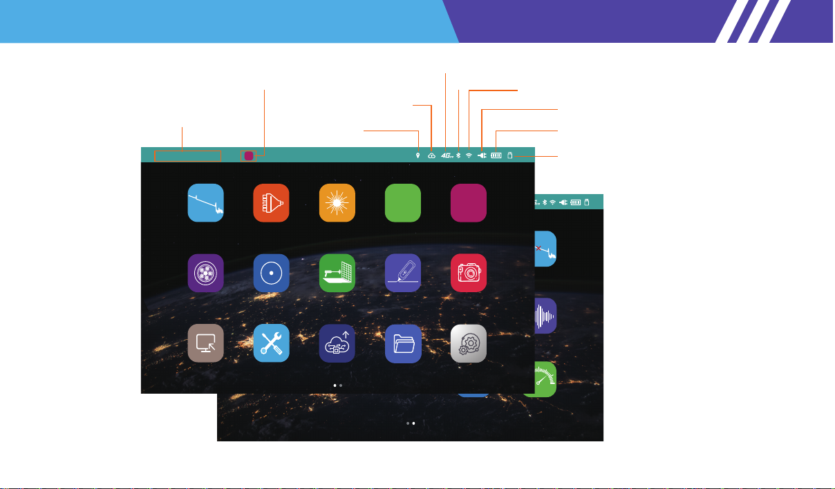
S2108 series optical network tester is the first smart and high precision optical test instrument with cloud wireless
transmission, intellignet cloud platform and other functions. S2108 series integrates 18 standard functional
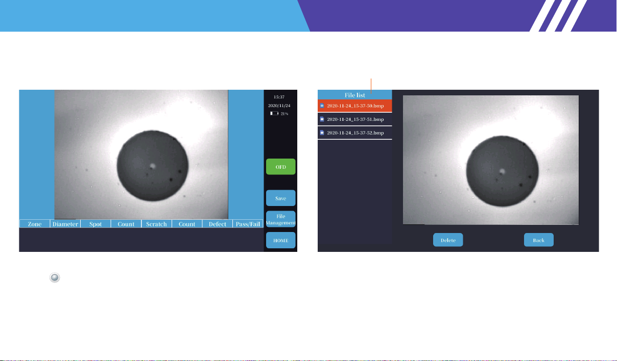
modules internally, including OTDR, Intellignet optical network map iONM, LS, VFL, OPM, Optical end face
detection, Multi-core measurement, Optical loss test, File management, Data wireless transmission, RJ45 cable
tracker, Laser ranging, Remote assistance, One-key repair, Camera, Bluetooth, WiFi, GPS&BDS (on
developing).
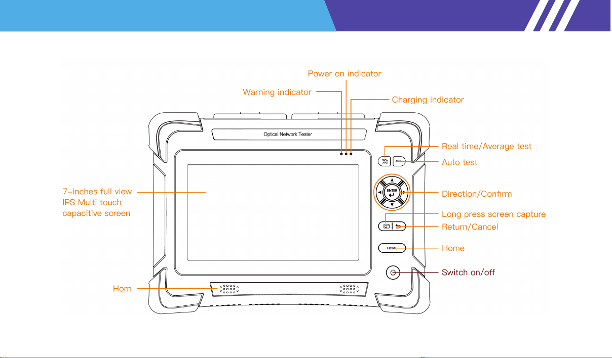
S2108 series has 0.8m event blind zone, maximum 45dB dynamic range, 1650nm online test (50dB isolation), 8G
storage which can store 200,000 curves. It adopts 7 inch capacitive touch screen, supports multi-point touch.
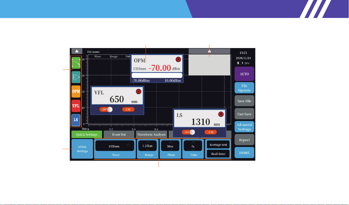
Compared to previous versions, it supports smart cloud platform, iONM, Multi-core measurement, Bluetooth.
WIFI, 4G LTE SIM and GPS (on developing), and test data can be uploaded to the cloud wirelessly. PDF reports
can be generated on the device and transmit them to the mobile terminal via WiFi & Bluetooth. S2108 series
supports multi-tasks simultaneous operation, and VFL, OPM, LS functions can run in the background.

OTDR Interface,function introduction

Mini USB connection:Connect the computer for data export, or connect the power bank to charge the device
USB connection:Accessing USB flash disk to export data, used as a power bank function to charge other devices
DC charging port:Charging voltage range 12V~19V
OTDR Interface,function introduction

Note: the main page is a sliding page, and the second page appears on the left
Fault-Location
2020/06/26
MonitorAbout
Fiber
Identification
SystemFile-BrowsCloud
Fast Repair
CameraRJ45 Tracker
Laster-rangingEndface
Inspector
Multi-Fiber
VFLOPM
VFL
Laser Source
OPM
dB/dBm/mW
iONMOTDR
2020/06/26 20:04:14
Remote-Help
Time and date
Background function open status display
USB connection
VFL
Battery power display
GPS positioning
Wifi
Charge indicator
Bluetooth
Fiber-iot
4G
OTDR Interface,function introduction

Multi task area
Curve full screen
Event map
OPM VFL LS
Multi task simultaneous operation
Optical fiber
characteristic setting
Pass/Fail Settings
Measure Settings
Analysis/Save Settings
Quick setting, no need to stop to modify conditions, convenient and fast
One button auto test
File operation
Preview / wireless upload to cloud
File save
Support Chinese and English input
One click save
Convenient and quick
Advanced setting
High end setting function
Generating reports
Generate PDF report on device side
Home
Return to the main interface
Curve thumbnail
OTDR Interface,function introduction

Graphic display type
More intuitive and accurate
Observe event information
List display
Type
Position length
loss
Reflect
Attenuation
Pass/Fail
Link-loss
Link ORL
Through multi wavelength and multi pulse width combination test technology,
the accurate analysis of various events is realized.
iONM
Interface,function introduction

Core matrix New project
Open project
Project property
Pictures of the scene
Core operation
Open file
Home
Measurement information
Waveform Preview End face detection
Multi core measurement
The purpose of multi-core measurement to help customers manage and maintain multi-core optical cable data,
Through the establishment of the project, to help customers more intuitive Manage and maintain fiber optic data.
From the core matrix, the state of all the cores can be seen intuitively, Including whether it has been tested,
does the test pass. Each fiber core contains OTDR data, optical fiber end face data, optical power data and test
field pictures

Save and view the optical fiber end face image
Optical fiber end face detection
The core diameter of single-mode fiber is about 9um, It's thinner than human hair, If the
end face is polluted, it will cause great connection loss, this leads to unstable communi-
cation state. It has great influence on the confidence of OTDR test results, therefore,
the end face of optical fiber is tested, and cleaning is very necessary

LS port location
On/Off
Mode switching
CW/270/330/1k/2kHz
Auto wave recognition
Power adjustable stable laser source Output CW/270Hz/330Hz/1kHz/2kHz mode
Support automatic wavelength recognition function, wavelength ID mode,
Combined with optical power meter module of series equipment for automatic wavelength identification
Increase power
Home
Reduce power
Laser Source
Background prompt of Laser Sourceon state

Measurement information
User calibration
Data acquisition
Automatic wavelength recognition
Support frequency identification function
Support pass / fail threshold setting
Support Tone Detect function,
namely frequency identification function
OPM port location OPM data acquisition interface
Optical power meter

Fault location and identification for short distance optical fiber
VFL port location
VFL
Background prompt of VFL state
VFL always bright
VFL 1Hz twinkle
VFL 2Hz twinkle
Home
Close VFL
Visual fault location

Laser ranging interface:
Please do not look directly at the laser emission port to avoid damage
Length measurement for optical cable laying and broadband installation
Single measurement
Continuous measurement
Home
Measurement information
Laster ranging

RJ45 digital radar tracking function can be used for digital line finding of network line,
telephone line and other cables
Digital/simulation switch
Whole
Line pair search
Close
Home
RJ45 tracker
Measurement information
RJ45 Digital tracking port
RJ45 tracker

Take pictures of the test site and link them to the OTDR test data
Photo display area
Photograph
Picture library
Home
Camera

Browse device files
Export files through USB flash disk
File add delete move rename
File upload to cloud platform
File type
File information
Create directory
Back to shortcut key Search
Open file
Cancel
Copy file
Cut file
Delete
Rename
Select all files
File upload to cloud
Bluetooth transmission
Home
File brows

System settings

Insert the U disk of storage upgrade software to upgrade the system
Connect WiFi remote upgrade
Software upgrade

Fiber-iot web: www.fiber-iot.com/tools/index.action
Scan QR code
Sign in Fiber-iot
Fiber-iot OTDR advanced simulation tools
You can log in directly fiber-iot web or Scan QR code,Imagine the advanced simula-
tion tool of OTDR,view OTDR data and generate reports
This manual suits for next models
14
Table of contents
Other Saluki Test Equipment manuals
Popular Test Equipment manuals by other brands

PCB Piezotronics
PCB Piezotronics VIBRATION DIVISION GK291D05 Installation and operating manual

American DJ
American DJ S-150/DMX User instructions

Svantek
Svantek SV258 PRO user manual

Keysight Technologies
Keysight Technologies 85052C User's and service guide

RS PRO
RS PRO SMD-100 instruction manual

DEWESOFT
DEWESOFT DS-CAL Software user manual