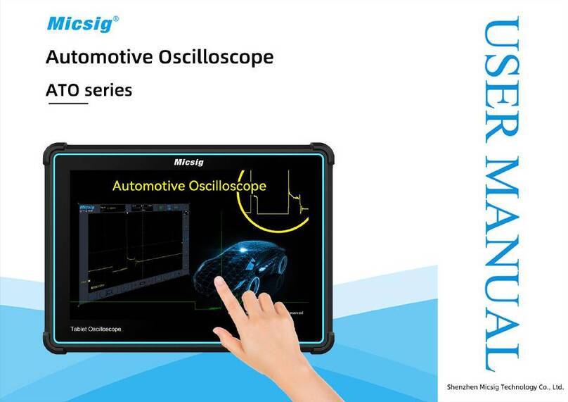
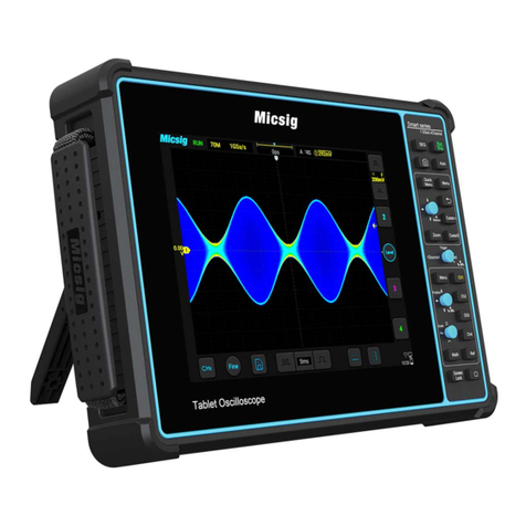
Micsig VATO Series User manual


Version Info
Version
Date
Remarks
V1.0
2024.01

Preface
Preface
Dear customers,
Congratulations! Thank you for buying Micsig instrument. Please read this manual carefully before use and
particularly pay attention to the “Safety Precautions”.
If you have read this manual, please keep it properly for future reference.
The information contained herein are furnished in an “as-is” state, and may be subject to change in future versions
without notice.
The standard applicable for this product: GB/T15289-2013.

Table of Contents
i
Table of Contents
TABLE OF CONTENTS......................................................................................................................................................... I
CHAPTER 1. SAFETY PRECAUTIONS................................................................................................................................... 1
1.1 SAFETY PRECAUTIONS.................................................................................................................................................... 1
1.2 SAFETY TERMS AND SYMBOLS........................................................................................................................................ 5
CHAPTER 2. QUICK START GUIDE OF OSCILLOSCOPE......................................................................................................... 8
2.1 INSPECT PACKAGE CONTENTS ........................................................................................................................................ 8
2.2 FRONT PANEL ................................................................................................................................................................ 9
2.3 REAR PANEL ................................................................................................................................................................ 10
2.4 POWER ON/OFF THE OSCILLOSCOPE............................................................................................................................... 11
2.5 CONNECT THE OSCILLOSCOPE ....................................................................................................................................... 11
2.6 UNDERSTAND THE OSCILLOSCOPE DISPLAY INTERFACE ................................................................................................. 17
2.7 INTRODUCTION BASIC OPERATIONS OF TOUCH SCREEN ................................................................................................. 23

ii
2.8 USE AUTO.................................................................................................................................................................... 25
2.9 LOAD FACTORY SETTINGS ............................................................................................................................................ 27
2.10 USE AUTO-CALIBRATION ............................................................................................................................................ 27
2.11 PASSIVE PROBE COMPENSATION ................................................................................................................................. 28
2.12 MODIFY THE LANGUAGE ............................................................................................................................................ 33
CHAPTER 3 AUTOMOTIVE TEST .......................................................................................................................................34
3.1 CHARGING/START CIRCUIT.................................................................................................................................................. 34
3.1.1
12V Charging.................................................................................................................................................... 36
3.1.2
24V Charging.................................................................................................................................................... 38
3.1.3
Alternator AC Ripple......................................................................................................................................... 39
3.1.4
Ford Focus Smart Generator............................................................................................................................... 40
3.1.5
12V Start ............................................................................................................................................................ 42
3.1.6
24V Start .......................................................................................................................................................... 45
3.1.7
Cranking Current .............................................................................................................................................. 46

Table of Contents
iii
3.2 SENSOR TESTS ................................................................................................................................................................ 48
3.2.1
ABS..................................................................................................................................................................... 49
3.2.2
Accelerator pedal ............................................................................................................................................... 51
3.2.3
Air Flow Meter.................................................................................................................................................... 53
3.2.4
Camshaft............................................................................................................................................................ 56
3.2.5
Coolant Temperature.......................................................................................................................................... 59
3.2.6
Crankshaft.......................................................................................................................................................... 61
3.2.7 Distributor............................................................................................................................................................. 63
3.2.8
Fuel pressure ...................................................................................................................................................... 65
3.2.9
Knock.................................................................................................................................................................. 67
3.2.10
Lambda ............................................................................................................................................................ 69
3.2.11
MAP ................................................................................................................................................................. 72
3.2.12
Road Speed....................................................................................................................................................... 75
3.2.13
Throttle Position............................................................................................................................................... 77
3.3 ACTUATORS.................................................................................................................................................................... 79
iv
3.3.1
Carbon canister solenoid valve ........................................................................................................................... 79
3.3.2
Disel Glow Plugs ................................................................................................................................................. 81
3.3.3
EGR Solenoid Valve............................................................................................................................................. 83
3.3.4
Fuel Pump .......................................................................................................................................................... 85
3.3.5
Idle speed control valve .................................................................................................................................... 87
3.3.6
Injector (gasoline engine) ................................................................................................................................. 89
3.3.7
Injector (Diesel) .................................................................................................................................................. 91
3.3.8
Pressure regulator............................................................................................................................................ 93
3.3.9
Quantity (Flow) control valve ............................................................................................................................. 95
3.3.10
Throttle Servo Motor........................................................................................................................................ 97
3.3.11
Variable speed cooling fan................................................................................................................................ 99
3.3.12
Variable valve timing...................................................................................................................................... 101
3.4 IGNITION TESTS............................................................................................................................................................. 103
3.4.1
Primary............................................................................................................................................................. 103
3.4.2
Secondary......................................................................................................................................................... 107

Table of Contents
v
3.4.3
Primary + Secondary......................................................................................................................................... 109
3.5 NETWORKS .................................................................................................................................................................. 112
3.5.1
CAN High & CAN Low ....................................................................................................................................... 112
3.5.2
LIN Bus ............................................................................................................................................................. 115
3.5.3
FlexRay Bus ...................................................................................................................................................... 117
3.5.4
K line ................................................................................................................................................................ 120
3.6 COMBINATION TESTS...................................................................................................................................................... 122
3.6.1
Crankshaft + Camshaft..................................................................................................................................... 122
3.6.2
Crankshaft + Primary ignition........................................................................................................................... 124
3.6.3
Primary ignition + Injector voltage ................................................................................................................... 126
3.6.4
Crankshaft + Camshaft + Injector + Secondary Ignition .................................................................................... 128
CHAPTER 4 HORIZONTAL SYSTEM..................................................................................................................................130
4.1 MOVE THE WAVEFORM HORIZONTALLY ...................................................................................................................... 132
4.2 ADJUST THE HORIZONTAL TIME BASE (TIME/DIV)....................................................................................................... 133

vi
4.3 PAN AND ZOOM SINGLE OR STOPPED ACQUISITIONS.................................................................................................... 136
4.4 ZOOM MODE........................................................................................................................................................... 137
CHAPTER 5 VERTICAL SYSTEM.......................................................................................................................................141
5.1 OPEN/CLOSE WAVEFORM (CHANNEL, MATH, REFERENCE WAVEFORMS)..................................................................... 143
5.2 ADJUST VERTICAL SENSITIVITY .................................................................................................................................. 148
5.3 ADJUST VERTICAL POSITION....................................................................................................................................... 149
5.4 OPEN CHANNEL MENU ............................................................................................................................................... 150
5.4.1 Set Channel Coupling........................................................................................................................................... 151
5.4.2 Set Bandwidth Limit ............................................................................................................................................ 153
5.4.3 Waveform Inversion ............................................................................................................................................ 154
5.4.4 Set Probe Type..................................................................................................................................................... 155
5.4.5 Set Probe Attenuation Coefficient........................................................................................................................ 156
5.4.6 Vertical expansion datum.................................................................................................................................... 158
5.4.7 Channel label....................................................................................................................................................... 158

Table of Contents
vii
CHAPTER 6 TRIGGER SYSTEM ........................................................................................................................................160
6.1 TRIGGER AND TRIGGER ADJUSTMENT ......................................................................................................................... 161
6.2 EDGE TRIGGER........................................................................................................................................................... 173
6.3 PULSE WIDTH TRIGGER .............................................................................................................................................. 177
6.4 SERIAL BUS TRIGGER ................................................................................................................................................. 184
CHAPTER 7 ANALYSIS SYSTEM .......................................................................................................................................185
7.1 AUTOMATIC MEASUREMENT....................................................................................................................................... 186
7.2CURSOR ...................................................................................................................................................................... 197
7.3 PHASE RULERS........................................................................................................................................................... 203
CHAPTER 8 STORAGE ....................................................................................................................................................204
8.1 SCREEN CAPTURE FUNCTION...................................................................................................................................... 205
8.2 WAVEFORM STORAGE ................................................................................................................................................ 205
8.3 OSCILLOSCOPE SETTING SAVE ..................................................................................................................................... 211
CHAPTER 9 MATH AND REFERENCE...............................................................................................................................213

viii
9.1 DUAL WAVEFORM CALCULATION ............................................................................................................................... 214
9.2 FFT MEASUREMENT .................................................................................................................................................. 219
9.3 REFERENCE WAVEFORM CALL.................................................................................................................................... 227
CHAPTER 10 DISPLAY SETTINGS.....................................................................................................................................232
10.1 COMMON SETTINGS .................................................................................................................................................. 233
10.2 GRATICULE SETTING ................................................................................................................................................ 234
CHAPTER 11 SAMPLING SYSTEM ...................................................................................................................................235
11.1 SAMPLING OVERVIEW............................................................................................................................................... 236
11.2 RUN/STOP KEY AND SINGLE SEQ KEY...................................................................................................................... 242
11.3 RECORD LENGTH AND SAMPLING RATE..................................................................................................................... 243
CHAPTER 12 SERIAL BUS TRIGGER AND DECODE ...........................................................................................................247
12.1 LIN BUS TRIGGER AND DECODE............................................................................................................................... 250
12.2 CAN BUS TRIGGER AND DECODE ............................................................................................................................. 257

Table of Contents
ix
CHAPTER 13 REFERENCE ...............................................................................................................................................264
13.1 MEASUREMENT CATEGORY....................................................................................................................................... 265
13.2 POLLUTION DEGREE ................................................................................................................................................. 267
CHAPTER 14 TROUBLESHOOTING..................................................................................................................................268
CHAPTER 15 SERVICES AND SUPPORT ...........................................................................................................................273
ANNEX..........................................................................................................................................................................275
ANNEX A:MAINTENANCE AND CARE OF OSCILLOSCOPE ................................................................................................... 275
ANNEX B: ACCESSORIES .................................................................................................................................................. 278


Chapter 1. Safety Precautions
1
Chapter 1. Safety Precautions
1.1 Safety Precautions
The following safety precautions must be understood to avoid personal injury and prevent damage to this product or
any products connected to it. To avoid possible safety hazards, it is essential to follow these precautions while using
this product.
⚫Only professionally trained personnel can operate the maintenance procedure.
⚫Avoid fire and personal injury.
⚫Use proper power cord. Use only the power cord specified for this product and certified for the country/region
of use.
⚫Connect and disconnect probes properly. Connect the instrument probe correctly, and its ground terminal is
ground phase. Do not connect or disconnect probes or test leads while they are connected to a voltage source.

2
Disconnect the probe input and the probe reference lead from the circuit under test before disconnecting the
probe from the measurement product.
⚫Ground the product. To avoid electric shock, the instrument grounding conductor must be connected to
earth ground.
⚫Observe all terminal ratings. To avoid fire or shock hazard, observe all rating and markings on the product.
Consult the product manual for further information of ratings before making connections to the product.
⚫User correct probes. To avoid excessive electric shock, use only correct rated probes for any measurement.
⚫Disconnect AC power. The adapter can be disconnected from AC power and the user must be able to access the
adapter at any time.
⚫Do not operate without covers. Do not operate the product with covers or panels removed.
⚫Do not operate with suspected failures. If you suspect that there is damage to this product, have it inspected
by service personnel designated by Micsig.

Chapter 1. Safety Precautions
3
⚫Use adapter correctly. Supply power or charge the equipment by power adapter designated by Micsig, and
charge the battery according to the recommended charging cycle.
⚫Avoid exposed circuitry. Do not touch exposed connections and components when power is present.
⚫Provide proper ventilation.
⚫Do not operate in wet/damp conditions.
⚫Do not operate in a flammable and explosive atmosphere.
⚫Keep product surfaces clean and dry.
⚫The disturbance test of all models complies with Class A standards, based on EN61326:1997+A1+A2+A3,
but do not meet Class B standards.
Measurement Category
The VATO series oscilloscope is intended to be used for measurements in Measurement Category I.

4
Measurement Category Definition
Measurement category I is for measurements performed on circuits not directly connected to the MAINS. Examples
are measurements on circuits not derived from MAINS, and specially protected (internal) MAINS derived circuits.
In the latter case, transient stresses are variable; for that reason, the user must understand the transient withstand
capability of the equipment.
Warning
IEC Measurement Category. Under IEC Category I mounting conditions, the input terminal can be connected to the
circuit terminal with a maximum line voltage of 300Vrms. To avoid the risk of electric shock, the input terminal
should not be connected to the circuit with a line voltage greater than 300Vrms. Instantaneous overvoltage is
present in circuits that are isolated from the mains supply. The VATO series digital oscilloscope is designed to
safely withstand sporadic transient overvoltage up to 1000Vpk. Do not use this equipment for any measurements in
circuits where the instantaneous overvoltage exceeds this value.

Chapter 1. Safety Precautions
5
1.2 Safety Terms and Symbols
Terms in the manual
These terms may appear in this manual:
Warning. Warning statements indicate conditions or practices that could result in injury or loss of life.
Caution. Caution statements indicate conditions or practices that could result in damage to this product or
other property.
Terms on the product
These terms may appear on the product:
Danger indicates an injury hazard immediately accessible as you read the marking.
Warning indicates an injury hazard not immediately accessible as you read the marking.
Caution indicates a hazard to this product or other properties.

6
Symbols on the product
The following symbols may appear on the product:
Hazardous Voltage Caution Refer to Manual Protective Ground Terminal
Chassis Ground Measurement Ground Terminal
Please read the following safety precautions to avoid personal injury and prevent damage to this product or
any products connected to it. To avoid possible hazards, this product can only be used within the specified
scope.
Warning
If the instrument input port is connected to a circuit with the peak voltage higher than 42V or the power exceeding
4800VA, to avoid electric shock or fire:

Chapter 1. Safety Precautions
7
⚫User only insulated voltage probes supplied with the instrument, or the equivalent product indicated in the
schedule.
⚫Before use, inspect voltage probes, test leads, and accessories for mechanical damage and replace when
damaged.
⚫Remove voltage probes and accessories not in use.
⚫Plug the battery charger into the AC outlet before connecting it to the instrument.
Table of contents
Other Micsig Test Equipment manuals

Micsig
Micsig SATO1000 Series User manual

Micsig
Micsig MS200 Series User manual

Micsig
Micsig MS300 Series User manual

Micsig
Micsig MDP Series User manual

Micsig
Micsig DP750 User manual

Micsig
Micsig RCP Series User manual

Micsig
Micsig Smart Series User manual

Micsig
Micsig tbook mini Series User manual

Micsig
Micsig DP5013 User manual

Micsig
Micsig ATO Series User manual