Teka StrongMaster 1-IFA User manual

Table of contents
1 General 3
2 Description of the system elements 4
2.1 Illustration of the system elements 4
2.2 Functionality of the system 4
2.3 Intended use 5
2.4. Residual risk 5
3 Safety instructions 6
3.1 Definition of the hazard symbols 6
3.2 General safety instructions 6
4 Storage, transport and installation of the device 7
5 Commissioning 8
5.1 Connecting an extraction element 8
5.2 Electrical connection 9
5.3 Precoating of the filter cartridges 9
6 Operating the system 10
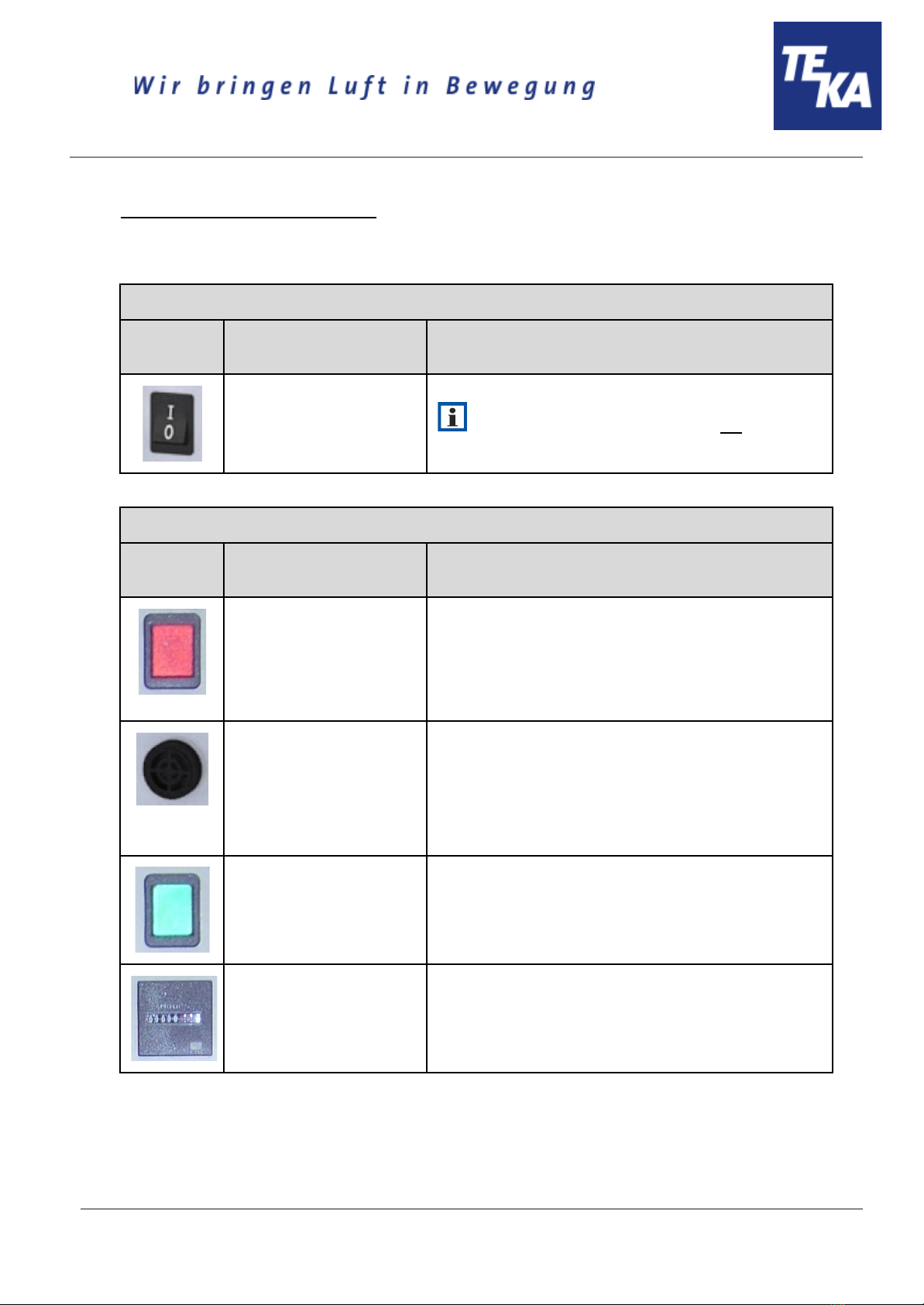
6.1 Explanation of the operating elements 10
7 Maintenance 11
7.1 Reset to maintenance state 12
7.2 Cleaning the filter cartridges 12
7.3 Replacing the filter cartridges 13
7.4 Emptying the dust collecting tank 17
7.5 Precoating of new filter cartridges 18
8 Dismantling / Disposal 19
9 Diagnostics and troubleshooting 19
10 List of spare parts 20
11 Technical data 21
12 EC declaration of conformity 22
13 Training protocol 23
14 Maintenance intervals 24
14.1 Usage-related maintenance 24
14.2 General maintenance 24
14.2.1 Visual inspection of the device 25
14.2.2 Functional test of the device 25
14.2.3 Electrical test of the electrical lines and earthing connections 26
BA_StrongMaster-1-und-2_IFA_20230808_EN
2
08.08.2023

1 General
Congratulations on purchasing the product from TEKA.
Our engineers ensure that our devices reflect the state of the art through continuous development.
Nevertheless, misuse or misconduct can endanger your safety. Please observe the following for a
successful use of the device:
Only authorised and instructed personnel can carry out transport, operation,
maintenance and repair of the device. The operator must ensure that the operating
personnel take note of these instructions.
Please read these instructions before operating the device, and observe the safety
precautions to avoid injury!
Store this manual in a safe place! These instructions are to be regarded as a component
of the product!
Adhere to all product notes!
Modifications or conversions that the operator carries out at the device without the
consent of the manufacturer, can lead to new safety hazards or to the loss of warranty
claims.
Observe the manufacturer’s instructions. Contact the manufacturer in case of any
uncertainty:
Tel: +49 2541-84841-0
E-mail: [email protected]
BA_StrongMaster-1-und-2_IFA_20230808_EN
3
08.08.2023

2 Description of the system elements
2.1 Illustration of the system elements
Installation example:
Z.Nr. 13464702
Pos.1
Pos.2
Pos.3
Pos.4
Pos.5
Pos.6
Operating elements
Dust collecting housing
Filter housing
Fan housing
Silencing housing
Service door for cleaning the filter
cartridges
Pos.7
Pos.8
Pos.9
Pos.10
Pos.11
Suction nozzle (StrongMaster 1: 1x,
StrongMaster 2: 2x)
Exhaust grille
Mains cable with plug
Swivel castor
Signal horn
2.2 Functionality of the system
The filter unit serves to suck off and filter polluted air (according to the intended use). The air is purified
on the surface of the filter cartridge in the filter section of the unit. The separated dust is collected in a
dust collecting tank. An automatic filter monitoring indicates when a cleaning or a replacement of the
filters is necessary. The purified air is led back into the working room via an exhaust air grille.
BA_StrongMaster-1-und-2_IFA_20230808_EN
4
08.08.2023

2.3 Intended use
The device is intended for commercial use. If the device is made publicly accessible, it must never be
operated unsupervised by authorized personnel, authorized by the operator.
The filter unit is intended for extraction and filtration of dusts and fumes that result from thermal joining
and cutting of metals. The filter unit is amongst others suitable for separating welding smokes of
unalloyed and alloyed steels as well as of high-alloy chromium-nickel steels and therefore meets the
highest welding fume separation category “W3” according to DIN EN ISO 21904-1 / -2.
WARNING
Improper use can damage parts and be a danger to life and limb!
The device must not be used for the extraction of oil-laden welding fume, explosive dust
and gases, hybrid mixtures, glowing or burning substances, gases, water, etc. The
device must not be operated in explosive zones.
Dangers arising from fire.
If the sucked medium is combustible fume or dust, the operator must determine
beforehand which fire protection measures are to be taken.
2.4. Residual risk
CAUTION
Danger due to possible hazardous materials in the exhaust air flow.
Because the unit does not monitor the quality of the air in the exhaust air flow, we
recommend that you always guide the exhaust air flow exiting our unit to areas (e.g. to the
outside into the open air) in which there is no danger to any living being. To do this, it is
necessary to fit a suitable exhaust air line at the filter unit.
BA_StrongMaster-1-und-2_IFA_20230808_EN
5
08.08.2023

3 Safety instructions
3.1 Definition of the hazard symbols
The device is constructed according to the state of the art and the recognised safety regulations.
Nevertheless, during use threats to life and limb of the user or other persons may arise. The impairment
of the machine or other property are also possible. In these instructions we warn by using corresponding
indications.
WARNING
WARNING
These instructions are made in case of risks that can lead to injury or death.
CAUTION
CAUTION
These instructions are made in case of risks that can lead to injury.
NOTICE
NOTICE
These instructions are made in case of risks that can lead to material damages.
Information notes are no hazard warnings; they call attention to useful information.
3.2 General safety instructions
WARNING
Dangers arising from improper use / unauthorised operations.
The operator must ensure that their authorised personnel are familiar with all the safety
indications in this manual in advance. The operator is responsible for ensuring that all work
is carried out by authorised and qualified personnel. We therefore recommend using the
training protocol on the last page for that purpose (see chapter “Training protocol”).
Laymen are allowed to operate the device after having received the necessary instructions.
But they are not allowed to carry out any installation, repair or maintenance work.
Dangers arising from fire.
In case of fire, if possible, switch the unit immediately off or disconnect it from the power
supply. Fire extinguishing measures which the operator is obliged to determine beforehand
must be initiated immediately.
BA_StrongMaster-1-und-2_IFA_20230808_EN
6
08.08.2023

WARNING
Dangers arising from electricity.
The operator must ensure that electrical plants and equipment are only built, modified and
maintained by a qualified electrician or under the direction and supervision of a qualified
electrician. Do not work on components if you are not sure that these are disconnected. If
necessary, disconnect the device from the electric power supply and secure it against
unauthorized restarting.
4 Storage, transport and installation of the device
WARNING
Risk of injury from tilting or unmounted components when stored or transported.
The device must be secured against tilting and slipping when it is stored or transported. Do
not stand under or next to the floating load. Lift trucks, forklift trucks and transport cranes
must have a sufficient minimum load bearing capacity. Pay attention to uneven grounds
during the transport. Avoid jerky pushing.
Dangers arising from titling or functional impairments at its destination.
The unit may only be set up on a suitable surface. The surface must be vibration-free and
horizontal. The operator must check the bearing capacity of the surface. As soon as the unit
has reached its intended destination, the brakes of the castors must be activated.
NOTICE
Damage or functional impairment of the unit due to climatic influences.
The unit must be stored in a dry place and protected against moisture during transport. As a
matter of principle, the filter unit is not designed to be installed outside.
BA_StrongMaster-1-und-2_IFA_20230808_EN
7
08.08.2023

5 Commissioning
WARNING
Dangers arising from a defective condition of the unit.
Make sure that the measures described in this chapter are completed before the
commissioning of the unit. All doors of the unit must be closed and all necessary connections
must be attached before turning the unit on. Do not operate the unit if any components are
defective, missing or damaged. Check the orderly condition of the unit before switching it on.
The unit must not be operated without a filter element.
NOTICE
Damaged supply lines.
Make sure that the supply lines are protected against damage by forklift trucks and similar
events. Protect all supply lines from heat, moisture, oil and sharp edges.
5.1 Connecting an extraction element
For extracting the contaminated air - according to the intended use - the provided extraction element
(e.g. suction arm, suction hose, ...) must be connected at the suction nozzle (see chapter 2.1).
The assembly of a suction arm is described in the separate operating manual.
When using a detection element with extraction hood, the extraction hood must track the welding seam,
possibly taking advantage of the thermally induced welding fume movements.
However, it is important to ensure that connections between the workpiece and the
extractor hood (and generally between the workpiece and filter device) are avoided, so that, if
necessary, the welding current cannot flow back through the protective conductor of the filter
device to the welding machine.
BA_StrongMaster-1-und-2_IFA_20230808_EN
8
08.08.2023

5.2 Electrical connection
NOTICE
Electric malfunction possible in cause of an incorrect power supply.
Pay attention to the admissible supply voltage. Please observe the specifications on the type
plate.
● Reconnect the mains cable (see chapter 2.1) to the power supply.
● Make sure that the fan impeller rotates in the required direction when switching it on for the first
time. If not, it results in a low extraction capacity. For visual inspection, there is a sticker
attached to the bottom of the dust collecting housing (see chapter 2.1). For the connection
points of 400V and 500V the rotating field might be incorrectly set and must be changed, if
necessary. Briefly switch the device on and off. The fan slowly starts running and the rotation
direction can be compared to the sticker.
When the fan rotates in the wrong direction, the extraction capacity is
reduced.
5.3 Precoating of the filter cartridges
For a longer service life of the filter cartridges we recommend to pretreat them with a filter aid. The
precoating can only be carried out during the commissioning at the operation site. When the operator
orders and installs new filter cartridges, we recommend to also precoat them before the commissioning.
Please read and refer to "Precoating new filter cartridges" in the chapter "Maintenance". There
you can also find a description of the operating method of the precoat.
BA_StrongMaster-1-und-2_IFA_20230808_EN
9
08.08.2023

6 Operating the system
6.1 Explanation of the operating elements
Operating elements for the device control
Representa
tion
Designation
Description / function
ON-OFF-switch
By means of this switch, the device is switched on and off.
When the device is switched off, it is not
disconnected from the power supply.
Operating elements for status and error messages
Representa
tion
Designation
Description / function
Signal lamp “red”
Flashing up means that the air-flow rate of the device is not
sufficient anymore. Filter elements must be cleaned or
replaced.
When using extraction elements with a suction hood, it is
possible that the throttle valve(s) in the suction hood are
closed. In this case open the throttle valves.
Signal horn
Honking signals that the air-flow rate of the device is not
sufficient anymore. Filter elements must be cleaned or
replaced.
When using extraction elements with a suction hood, it is
possible that the throttle valve(s) in the suction hood are
closed. In this case open the throttle valves.
Indicator lamp “green”
Flashing up means that the device is in operation.
Operating hour counter
The number of operation hours during which the device was in
operation is shown.
BA_StrongMaster-1-und-2_IFA_20230808_EN
10
08.08.2023

7 Maintenance
In accordance with national regulations, the operator is obliged to carry out repeat and functional tests.
Unless otherwise specified by national regulations, we recommend regular visual inspections and
functional tests of the device as described in the chapter “Maintenance intervals”.
You find the chapter “Maintenance intervals” at the end of the document. The general
maintenance (visual inspection, etc.) is also explained there.
In the chapter “Maintenance intervals” there is information on the maintenance intervals of the filter
elements. But these are only recommendations. Depending on the application (multi-shift operation,
dust generation, ...) it may be necessary for the operator to change the maintenance intervals.
In this chapter the maintenance work which is caused by wear caused during operation is described.
WARNING
Work on the open system entails the risk of electrical shock or accidental restart the
system. Both pose a danger to life and limb.
When cleaning and servicing equipment during the replacement of parts or when changing
to another function, set the device to maintenance condition first (see chapter “Reset to
maintenance state”).
A recommissioning of the device must only occur if it is ensured that the device is
functionally equivalent to the original state.
CAUTION
Hazards to the respiratory tracts are possible due to contact with contaminated filter
elements.
All maintenance work must only be carried out in well-ventilated rooms and while wearing an
appropriate respiratory mask! We recommend: respiratory protection half mask DIN EN
141/143 protection level P3. For all maintenance work ensure a cautious handling of filter
elements and components in order to avoid whirling up dust.
The operator is obliged to store and dispose of the collected dust in accordance with national or
regional regulations. For all maintenance or cleaning work please refer to the applying
environmental regulations. Pollutants and filter elements must be disposed of or stored according
to the regulations as well. If you have any doubts, we recommend contacting a disposal
contractor in your area.
BA_StrongMaster-1-und-2_IFA_20230808_EN
11
08.08.2023

7.1 Reset to maintenance state
● Switch off the unit. Unplug the mains plug. Secure the unit against unauthorized restarting
during maintenance.
● After completion of all maintenance work the unit can be reconnected to the power supply.
7.2 Cleaning the filter cartridges
The filter cartridges are reusable filters and can be cleaned. The cleaning of the filter cartridges is
carried out manually.
The degree of pollution of the filter cartridges is electronically monitored. When the maximal admissible
differential pressure value is reached, the device triggers “filter alarm” (see chapter “description of the
control elements”). Now a cleaning is necessary. If despite of the cleaning of the filter cartridge the
alarm value is not undercut anymore, the filter cartridge must be replaced. (see chapter: “Replacing the
filter cartridges”).
● Close all front service doors in case they are open. When using a suction arm as an extraction
element, close the throttle valve at their suction hood.
In case the service doors are open, dust can escape during the cleaning.
● Open the rear service door of the filter housing.
● Use a compressed air pistol for the cleaning. These must be connected to the external
compressed air supply of the operator.
The compressed air must be dry and oil-free. The operating pressure must be
between 3 and 4 bars.
BA_StrongMaster-1-und-2_IFA_20230808_EN
12
08.08.2023

● Hold the compressed air pistol into the interior of the filter cartridge. Blow steadily with the
compressed air pistol into the crinkles of the filter cartridge. Clean it for at least 5 minutes.
● Close the rear service door of the filter housing.
● When using a suction arm as an extraction element, open the throttle valve at their suction
hood.
7.3 Replacing the filter cartridges
Replacing the filter cartridges becomes necessary when the filter cartridges are saturated with dirt in a
manner that despite of the cleaning the filter alarm is triggered again at very short intervals or
permanently. (The filter alarm is described in chapter “Cleaning the filter cartridges”.)
CAUTION
Whirling up dust is possible due to the polluted filter cartridges.
The filter cartridges must be cleaned before being replaced. Proceed as described in chapter
“cleaning of the filter cartridges”. After cleaning the filter cartridges wait about 5 minutes
before opening the service door of the filter housing.
We recommend to pretreat new filter cartridges with filter aid (e.g. precoat) before the first
commissioning. Refer to the chapter "Precoating new filter cartridges".
BA_StrongMaster-1-und-2_IFA_20230808_EN
13
08.08.2023

● We recommend that two people work
together to replace the filter cartridges.
● We recommend spreading out a protective
film in order to keep the area around the unit
clean.
●The filter cartridges may only
be replaced in well-ventilated rooms and
while wearing an appropriate respiratory
mask! We recommend: Respiratory
protection half mask DIN EN 141/143
protection level P3.
● We also recommend using additional
protective clothing such as gloves,
disposable overalls and protective eyewear.
● Before replacing the filter cartridges, make
sure you have a suitable container (e.g. PE
bag) for disposal.
The contaminated filter
cartridges must be packed in a suitable
container (e.g. PE bag). PE bags are
available as an option (see spare parts
list)! We recommend that you procure
disposal bags at an early stage.
● Open the filter housing's service door.
● Loosen the fixing screw. This is located at
the bottom of the cartridge holder. Loosen
the fixing screw but do not unscrew it from
the cartridge holder It is important that the
cartridge holder is still held loosely.
BA_StrongMaster-1-und-2_IFA_20230808_EN
14
08.08.2023

● Pull the disposal bag over the cartridge
holder and filter cartridge.
● Unhook the cartridge holder from the
cartridge guides.
● Remove the cartridge holder with the filter
cartridge and the disposal bag from the filter
housing.
● Briefly lift the filter cartridge in order to
release it from the cartridge holder.
● Next, pull the cartridge holder with little dust
on it out of the disposal bag and past the
filter cartridge.
● Undo the screw connection that is fixed at
the base of the filter cartridge. This screw
connection must be attached at the base of
the new filter cartridge. When this is done,
the head of the screw must face outwards.
BA_StrongMaster-1-und-2_IFA_20230808_EN
15
08.08.2023

● Seal the disposal bag (e.g. with cable ties).
The operator is obliged to store and
dispose of contaminated filter
cartridges in accordance with
national or regional regulations.
.
●First of all, remove all the filter cartridges as described in the steps above.
●Only then should you start to install the new filter cartridges.
Only use TEKA replacement filters. Otherwise the correct functioning of the unit
is not guaranteed.
● Insert the new filter cartridge in the cartridge
holder. When you do this, the fixing screw
must engage in the head of the screw that is
attached at the base of the filter cartridge.
● Insert the cartridge holder with the new filter
cartridge in two of the cartridge guides.
● Screw the fixing screw tight.
If the fixing screw is not
properly tightened then the seal at the top
of the filter cartridge may not be pressed
on sufficiently.
● Close the service door.
BA_StrongMaster-1-und-2_IFA_20230808_EN
16
08.08.2023

7.4 Emptying the dust collecting tank
The dust collection container must be cleaned after a certain number of operating hours. This range
depends on the amount of dust. The filling level has to be proofed at least once a week.
CAUTION
Whirling up dust is possible due to the polluted filter cartridges!
The filter cartridges must be cleaned before emptying the dust collecting tank. The
proceeding of the cleaning is described in the chapter “Cleaning of filter cartridges”. After
cleaning the filter cartridges wait about 5 minutes before opening the service door.
Before emptying the dust collecting tank hold ready an appropriate container (e.g. PE bag). The
bags are optionally available at TEKA, see list of spare parts. We recommend having PE bags in
stock.
● Open the service door of the dust collecting housing (see chapter 2.1).
● Lower the lifting device (B) by turning the clamping screw (C). Therefore, use the hexagon key
that is located on the right of the clamping screw.
● Carefully pull the dust collecting tank (A) out of the housing.
● Close the dust collection bag (e.g. with a cable fastener).
● Remove the dust collection bag and store or dispose of it according to the regulations.
● Place a new dust collection bag in the dust collection container so that the bag is put over the
edge of the dust collection container.
● Push the dust collecting tank back into the dust collecting housing.
● Elevate the lifting device by turning the clamping screw so that the dust collection container is
pressed tightly against the above housing.
● Close the service door.
BA_StrongMaster-1-und-2_IFA_20230808_EN
17
08.08.2023

7.5 Precoating of new filter cartridges
Before the first commissioning new filter cartridges can be pre-treat with precoat consumable. The
precoat consumable assists against a "caking" of extracted particles on the filter surface and thus
prolongs the life of the new filter cartridge
Unlike with other maintenance work, this step must be carried out with the system switched on and
operating. This is necessary to allow the filter aid to disperse on the surface of the filter cartridges
through suction.
CAUTION
On contact the precoat consumable can be hazardous to the
respiratory tract and cause skin irritation or eye irritation.
Observe the listed manufacturer instructions provided:
Handling: Avoid the formation of dust!
Storage: Seal the container tightly before storage!
Respiratory protect: Dust mask without protection level!
Hand protection: Protective gloves in cloth, rubber or leather!
Eye protection: Safety glasses with side shields!
Body protection: Anti-static work shoes!
● Provide sufficient filter aid. We recommend using 10 grams for each square metre of the filter
surface. The filter aid is available at TEKA (see list of spare parts).
● Choose the capture point in the suction pipe that is the closest to the filter cartridges. E.g. an
inspection flap can be used as a capture point.
Electrical short-circuit due to LED lighting possible. If the extraction cowl of a
suction arm is chosen as an extraction point then this extraction cowl may only be used
if it is not equipped with LED lighting. Otherwise, the filter aid must not be extracted via
the extraction cowl but, for example, via the hose of the suction arm by disconnecting
this from the extraction cowl for this period.
● Switch the device on.
● Let the filter aid bit by bit be sucked in via the capture point.
BA_StrongMaster-1-und-2_IFA_20230808_EN
18
08.08.2023

8 Dismantling / Disposal
Only authorised personnel may disassemble the machine.
WARNING
Dangers arising from electricity.
Before the dismantling of the machine it has to be disconnected from the power supply and
all supply lines.
CAUTION
Whirling up dust is possible due to the deposited dust.
During all work a suitable respiratory protection and protective clothing have to be worn.
The operator is obliged to store and dispose of the collected dust in accordance with national or
regional regulations.
9 Diagnostics and troubleshooting
A list of possible system errors is provided in the table.
Faults indicated by control elements are explained in the chapter “Description of the control
elements”.
A recommissioning of the device must only occur if it is ensured that the system is functionally
equivalent to the original state. Repairs may only be carried out by TEKA personnel or, after
consultation with TEKA GmbH, by the personnel authorised by the operator.
Adhere to the instructions in the chapter "Safety instructions" and " Maintenance" when carrying out any
repairs. If in doubt, contact our TEKA service department:
Tel: +49 2541-84841-0
E-mail: [email protected]
Fault
Cause
Removal
System does not start.
Plug power supply is missing or
incorrectly inserted.
Plug connector check power
supply / plug in correctly.
No power at outlet.
Check the mains, remove error if
possible.
Dust at the dust
collecting tank.
There is too much dust in the dust
collection container.
Empty the dust collecting tank.
The lifting device has not been lift up.
Screw up the lifting device.
The seal of the dust collecting tank is
damaged.
The seal must be replaced.
BA_StrongMaster-1-und-2_IFA_20230808_EN
19
08.08.2023

Dust at the service door
of the filter housing.
The door is not correctly closed.
Close the door.
The seal between the service door and
filter housing is damaged.
The seal must be replaced.
Escape of dust at the hinge.
The hinge must be reoriented or
replaced.
Suction power too low
(smoke hardly
extracted).
Filter element is saturated.
Replace the filter package,
dispose of old filter properly!
Damage at the extraction elements.
Replace the extraction elements.
The motor rotates in the wrong
direction.
The rotating field of mains
connection point must be
changed.
Suction line contracted.
Check and fix.
Exhaust line contracted.
Check and fix.
Maybe throttle valves are used in the
suction line.
Adjust throttle valves.
The system is very noisy.
The motor rotates in the wrong
direction.
The rotating field of mains
connection point must be
changed.
The unit is untight.
Check and fix.
10 List of spare parts
Filter element
Article no.
Filter cartridge, Type “BIA-M”, 10,0m² (Ø327 x 600 mm)
(StrongMaster 1: 1 piece of these filter elements is required for the device)
(StrongMaster 2: 2 pieces of these filter elements are required for the device)
6160600110008
Disposal elements
Article no.
PE-bag for the disposal of filter cartridges (4 pieces)
10030251702
PE-bag for inserting into the dust collecting tank (10 pieces)
10030250
Precoat consumable
Article no.
Precoat for filter cartridges, 400g (im Eimer)
951004
Precoat für filter cartridges, 100g (im Eimer)
9510050001
BA_StrongMaster-1-und-2_IFA_20230808_EN
20
08.08.2023
This manual suits for next models
5
Table of contents