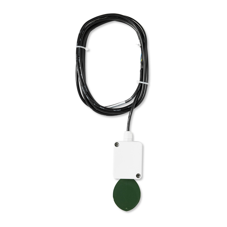
Tekbox TBSCS1 User manual

V1.3
TBSCS1
SDI-12 COMPASS / INCLINATION SENSOR
© 2022 Tekbox Digital Solutions
Factory 4, F5, Lot I-3B-1 | Saigon Hi-Tech Park | Tan Phu Ward, District 9 | Ho Chi Minh City | Tel +84 (83)5471340
The TBSCS1 is a 3D compass and inclination sensor with SDI-12 interface. It measures heading,
roll angle and pitch angle.
The sensor is used in agricultural yield applications to monitor the operation of center pivot
irrigation systems or the status of flood gates.
Features
▪3D Compass and inclination sensor
▪Measurement range: 0° to 360°heading,
▪-90° to +90° roll, -90° to +90° pitch
▪Measurement response: 3 sec
▪SDI-12 Standard V1.4
▪Plug and Play
▪6 - 16V supply voltage
▪Operating Temperature Range:
- 40°C … + 80°C
▪Weight: 80g
Target Applications
▪Monitoring of flood gates
▪Monitoring of center pivot irrigators
TBSCS1 SDI-12 compass / inclinometer

V1.3
TBSCS1
SDI-12 COMPASS / INCLINATION SENSOR
2
Contents
1INTRODUCTION 4
1.1 PRODUCT SPECIFICATIONS 4
1.2 CALIBRATION 5
1.3 DEFAULT PARAMETERS 6
1.4 INSTALLATION 6
1.5 SDI-12 7
2MEASUREMENT 7
2.1 ROLL,PITCH AND HEADING MEASUREMENT 7
2.2 TEMPERATURE MEASUREMENT 8
2.3 HARD-IRON AND SOFT-IRON COMPENSATION MEASUREMENT 8
2.4 MAGNETIC DECLINATION COMPENSATION 8
3APPLICATION EXAMPLES 9
4HARDWARE DESCRIPTION 10
4.1 CABLE CONNECTION 10
5SUPPORTED SDI-12 V1.3 COMMANDS 10
6SUPPORTED SDI-12 V1.4 COMMANDS 11
7SUPPORTED EXTENDED COMMANDS 15
7.1 SETTING ENGINEERING UNITS 15
7.2 INITIALIZATION 15
7.3 INTERNAL PARAMETERS 16
8ORDERING INFORMATION 17
9HISTORY 17
Tables
Table 1 –Cable Connection 10
Table 2 –Standard SDI-12 v1.3 commands 11
Table 3 –Standard SDI-12 v1.4 commands 15
Table 4 –Extended SDI-12 Commands –Engineering Units 15
Table 5 –Extended SDI-12 Commands - Initialization 15
Table 6 –Extended SDI-12 Commands –Internal parameters 16
Table 7 –Ordering Information 17
Table 8 –History 17
Figures
Figure 1 –TBSCS1 board 4
Figure 2 –TBSCS1 –Roll, Pitch and Heading axis 5
Figure 3 –terminal block pin assignment 6

V1.3
TBSCS1
SDI-12 COMPASS / INCLINATION SENSOR
3
Figure 4 –TBSCS1 and other sensors with SDI-12 interface connected to TBS03 SDI-12 to USB converter;
setup for controlling / testing sensors and for PC based data recording 9
Figure 5 –TBSCS1 and other sensors with SDI-12 interface connected to Remote Telemetry Unit or Data
Recorder 9

V1.3
TBSCS1
SDI-12 COMPASS / INCLINATION SENSOR
4
1 Introduction
The TBSCS1 is a rugged compass sensor/inclinometer with SDI-12 interface. It is mounted inside an IP67
housing from Fibox.
Figure 1 –TBSCS1 board
1.1 Product specifications
•Compass heading range: 0 to 360°, ±3° accuracy
•Roll angle range: -90° to +90°, ±2° accuracy
•Pitch angle range: -90° to +90°, ±2° accuracy
•Measurement response: 3 sec
•SDI-12 Standard V1.4
•6 - 16V supply voltage
•Operating Temperature Range: - 40°C … + 80°C
•Weight: 0,08kg
•Current consumption: active 17mA; idle 1.8mA.
•Standard cable length: 3m; any other length upon requirement

V1.3
TBSCS1
SDI-12 COMPASS / INCLINATION SENSOR
5
1.2 Calibration
The heading calculation relies on an accurate measurement of the magnetic field. However the measurement
accuracy is impacted by both hard-iron and soft-iron phenomenons.
It is then required to proceed with a specific procedure that will measure the hard-iron and soft-iron corrections
that will be automatically applied while measuring the heading.
In that case, M2! command shall be sent only once and at the place where TBSCS1 is used. This measurement
procedure must be done again whenever TBSCS1 is moved to another place in order to ensure a suitable
accuracy.
The hard-iron and soft-iron measurements procedure takes 20 seconds.
Upon execution of M2!, TBSCS1 shall be fully rotated:
•Around its 3 axis as defined by the industry standard NED (North, East, Down) coordinates system:
Figure 2 –TBSCS1 –Roll, Pitch and Heading axis
•And then for different pitch and roll positions.

V1.3
TBSCS1
SDI-12 COMPASS / INCLINATION SENSOR
6
Performing hard-iron and soft-iron measurement is only needed when TBSCS1 is used to calculate the heading.
In case only the roll and pitch are measured, this procedure can be skipped.
Hard-iron and soft-iron correction parameters can be cleared with extended command aXSHS,0! meaning that
no compensation will be applied while measuring the heading (which is not recommended since it will entail a
significant error on the calculated heading).
1.3 Default parameters
TBSCS1 is shipped with following default parameters:
•SDI-12 address: 0
•Temperature unit: degree Celcius
•Hard-iron compensation: none (Mag_X, Mag_Y and Mag_Z offset: 0 mGauss)
•Soft-iron compensation: none (Mag_X, Mag_Y and Mag_Z scaling factor: 1)
•Magnetic declination: 0 degree.
1.4 Installation
The TBSCS1 is compatible with any data logger or remote telemetry unit with SDI-12 interface. Refer to the data
logger or RTU manual and to chapter 2 and 3 of this datasheet. Chapter 2 refers to the electrical installation;
chapter 3 refers to the mechanical drawings.
The TBSCS1 shall ideally be mounted in at least 1,5 meters distance from iron objects if the compass feature is
used.
Figure 3 –terminal block pin assignment
+12V
Data
Ground
d

V1.3
TBSCS1
SDI-12 COMPASS / INCLINATION SENSOR
7
1.5 SDI-12
SDI-12 is a standard for interfacing data recorders with microprocessor-based sensors. SDI-12 stands for
serial/digital interface at 1200 baud. It can connect multiple sensors with a single data recorder on one cable. It
supports up to 60 meter cable between a sensor and a data logger.
The SDI-12 standard is prepared by
SDI-12 Support Group
(Technical Committee)
165 East 500 South
River Heights, Utah
435-752-4200
435-752-1691 (FAX)
http://www.sdi-12.org
TBSCS1 is SDI-12 v1.4 compliant.
2 Measurement
The TBSCS1 outputs compass heading, roll angle, pitch angle and board temperature.
2.1 Roll, pitch and heading measurement
TBSCS1 embeds an accelerometer that allows calculating the pitch and roll whereas the heading is calculated
with the embedded magnetometer. The reported values are in degree.
With respect to heading measurement, TBSCS1 not only applies hard-iron and soft-iron compensation on the
measured magnetic field (as described in the calibration procedure) but also includes an algorithm that
automatically performs tilt compensation.
Above compensations are automatically carried out while issuing M! measurement command.
Due to TBSCS1 design, the sensor must be used in static conditions for full accuracy or in slow motion.
Supported measurement commands:
aM! aMC! aC! aCC! roll angle, pitch angle, compass heading
Notes:
•The angles are measured in degrees.
•The measured heading is magnetic heading pointed by the Heading arrow at the top of TBSCS1.

V1.3
TBSCS1
SDI-12 COMPASS / INCLINATION SENSOR
8
2.2 Temperature measurement
TBSCS1 3D accelerometer and magnetometer module provides an embedded temperature sensor. It shall be
used for getting temperature indication rather than an precise measurement like with a PT1000.
Supported measurement commands:
aM1! aMC1! aC1! aCC1! internal temperature
The measurement unit is C by default, but it can be configured to F through extended SDI-12 command
XSTUC!/XSTUF!.
2.3 Hard-iron and soft-iron compensation measurement
While performing the hard-iron and soft-iron measurements, M2! returns the calculated hard-iron offsets
(Mag_X_HI, Mag_Y_HI, Mag_Z_HI in mGauss) and soft-iron scaling factor (Mag_X_SI, Mag_Y_SI, Mag_Z_SI).
Supported measurement commands:
aM2! aMC2! aC2! aCC2! Mag_X_HI, Mag_Y_HI, Mag_Z_HI, Mag_X_SI, Mag_Y_SI, Mag_Z_SI
These corrections can be reset to their default values with extended SDI-12 command XSHS,0!.
2.4 Magnetic declination compensation
The heading is measured vs the magnetic North. If the user needs to get the heading aligned with the true North
or simply desires to set a custom reference direction, an offset can be applied to the final calculation through the
extended command aXSMD,sn!.
Valid offset ranges from -90 to +90 degrees.

V1.3
TBSCS1
SDI-12 COMPASS / INCLINATION SENSOR
9
3 Application Examples
Figure 4 –TBSCS1 and other sensors with SDI-12 interface connected to TBS03 SDI-12 to USB converter; setup for
controlling / testing sensors and for PC based data recording
Figure 5 –TBSCS1 and other sensors with SDI-12 interface connected to Remote Telemetry Unit or Data Recorder
TBSCS1
TBSCS1

V1.3
TBSCS1
SDI-12 COMPASS / INCLINATION SENSOR
10
4 HARDWARE DESCRIPTION
Refer to http://www.fibox.com/catalog/1995/product/609/7032520_ENG3.html with respect to the mounting holes
of the housing.
4.1 Cable Connection
Cable Color
Signal Assignment
Blue
SDI-12 Power
Yellow-Green
SDI-12 Data
Blue
GND
Black
GND
Table 1 –Cable Connection
5 SUPPORTED SDI-12 V1.3 COMMANDS
Following commands are supported by the TBSCS1:
Command
Description
Response
a!
Acknowledge Active
a<CR><LF>
aI!
Send Identification
a14TEKBOXVNTBSCS1rv<h><nnnnnn><fffffff><CR><LF>
With:
o<a>: SDI-12 address
o<h>: HW revision (one letter)
o<nnnnnn>: serial number (6 digits)
o<fffffff>: firmware version (7 digits)
Example:
014TEKBOXVNTBSCS1rvB1234561200101<CR><LF>
aAb!
Change Address
b<CR><LF>
Changing the sensor address from a to b
?!
Address Query
a<CR><LF>
aM!
Start Measurement
Measures roll, pitch and heading (in degrees)
a0033<CR><LF>
Delay: (3) seconds and number of values (3)
aM1!
Additional Measurement
Measures internal temperature
a0011<CR><LF>
Delay: (1) seconds and number of values (1)

V1.3
TBSCS1
SDI-12 COMPASS / INCLINATION SENSOR
11
aM2!
Additional Measurement
Measures hard-iron and soft-iron parameters
a0206<CR><LF>
Delay: (20) seconds and number of values (6)
aMC!
Start Measurement and request CRC
Measures roll, pitch and heading (in degrees)
and calculates CRC
a0033<CR><LF>
Delay: (3) seconds and number of values (3)
aMC1!
Additional Measurement and request
CRC
Measures internal temperature and calculates
CRC
a0011<CR><LF>
Delay: (1) seconds and number of values (1)
aMC2!
Additional Measurement
Measures hard-iron and soft-iron parameters
and calculates CRC
a0206<CR><LF>
Delay: (20) seconds and number of values (6)
aC!
Start Concurrent Measurement
Measures roll, pitch and heading (in degrees)
a00303<CR><LF>
Delay: (3) seconds and number of values (3)
aC1!
Start Concurrent Measurement
Measures internal temperature
a00101<CR><LF>
Delay: (1) seconds and number of values (1)
aC2!
Additional Measurement
Measures hard-iron and soft-iron parameters
a02006<CR><LF>
Delay: (20) seconds and number of values (6)
aCC!
Start Concurrent Measurement and
request CRC
Measures roll, pitch and heading (in degrees)
and calculates CRC
a00303<CR><LF>
Delay: (3) seconds and number of values (3)
aCC1!
Start Concurrent Measurement and
request CRC
Measures internal temperature and calculates
CRC
a00101<CR><LF>
Delay: (1) seconds and number of values (1)
aCC2!
Additional Measurement
Measures hard-iron and soft-iron parameters
and calculates CRC
a02006<CR><LF>
Delay: (20) seconds and number of values (6)
aD0!
Get Measurement Result(s)
Upon issuing the aD0! Command, the TBSCS1 will send
the measurement results. The response format depends
on the measurement command issued before.
aV!
Start Verification
a0000<CR><LF>
Not supported
aRn!
aRCn!
Continuous Measurement
Continuous Measurement + CRC
a<CR><LF>
Not supported
Table 2 –Standard SDI-12 v1.3 commands
6 SUPPORTED SDI-12 V1.4 COMMANDS
Command
Description
Response
aIM!
aM! Identify Measurement
Returns delay and number of parameters
a0033<CR><LF>
Delay: (3) seconds and number of values (3)
aIMC!
aMC! Identify Measurement
Returns delay and number of parameters
a0033<CR><LF>
Delay: (3) seconds and number of values (3)

V1.3
TBSCS1
SDI-12 COMPASS / INCLINATION SENSOR
12
aIC!
aC! Identify Measurement
Returns delay and number of parameters
a00303<CR><LF>
Delay: (3) seconds and number of values (3)
aICC!
aCC! Identify Measurement
Returns delay and number of parameters
a00303<CR><LF>
Delay: (3) seconds and number of values (3)
aIM1!
aM1! Identify Measurement
Returns delay and number of parameters
a0011<CR><LF>
Delay: (1) seconds and number of values (1)
aIMC1!
aMC1! Identify Measurement
Returns delay and number of parameters
a0011<CR><LF>
Delay: (1) second, number of values (1)
aIC1!
aC1! Identify Measurement
Returns delay and number of parameters
a00101<CR><LF>
Delay: (1) second and number of values (01)
aICC1!
aCC1! Identify Measurement
Returns delay and number of parameters
a00101<CR><LF>
Delay: (1) second, number of values (1)
aIM2!
aM2! Identify Measurement
Returns delay and number of parameters
a0206<CR><LF>
Delay: (20) seconds and number of values (6)
aIMC2!
aMC2! Identify Measurement
Returns delay and number of parameters
a0206<CR><LF>
Delay: (20) seconds and number of values (6)
aIC2!
aC2! Identify Measurement
Returns delay and number of parameters
a02006<CR><LF>
Delay: (20) seconds and number of values (6)
aICC2!
aCC2! Identify Measurement
Returns delay and number of parameters
a02006<CR><LF>
Delay: (20) seconds and number of values (6)
aIM_001!
aM! Identify Measurement
Parameters (1rst)
Returns parameter’s identification and unit
a,Roll,Degree(Angle);<CR><LF>
aIMC_001!
aMC! Identify Measurement
Parameters (1rst)
Returns parameter’s identification and unit
a,Roll,Degree(Angle);<CRC><CR><LF>
aIC_001!
aC! Identify Measurement
Parameters (1rst)
Returns parameter’s identification and unit
a,Roll,Degree(Angle);<CR><LF>
aICC_001!
aCC! Identify Measurement
Parameters (1rst)
Returns parameter’s identification and unit
a,Roll,Degree(Angle);<CRC><CR><LF>
aIM_002!
aM! Identify Measurement
Parameters (2nd)
Returns parameter’s identification and unit
a,Pitch,Degree(Angle);<CR><LF>
aIMC_002!
aMC! Identify Measurement
Parameters (2nd)
Returns parameter’s identification and unit
a,Pitch,Degree(Angle);<CRC><CR><LF>
aIC_002!
aC! Identify Measurement
Parameters (2nd)
Returns parameter’s identification and unit
a,Pitch,Degree(Angle);<CR><LF>
aICC_002!
aCC! Identify Measurement
Parameters (2nd)
Returns parameter’s identification and unit
a,Pitch,Degree(Angle);<CRC><CR><LF>

V1.3
TBSCS1
SDI-12 COMPASS / INCLINATION SENSOR
13
aIM_003!
aM! Identify Measurement
Parameters (3rd)
Returns parameter’s identification and unit
a,Yaw,Degree(Angle);<CR><LF>
aIMC_003!
aMC! Identify Measurement
Parameters (3rd)
Returns parameter’s identification and unit
a,Yaw,Degree(Angle);<CRC><CR><LF>
aIC_003!
aC! Identify Measurement
Parameters (3rd)
Returns parameter’s identification and unit
a,Yaw,Degree(Angle);<CR><LF>
aICC_003!
aCC! Identify Measurement
Parameters (3rd)
Returns parameter’s identification and unit
a,Yaw,Degree(Angle);<CRC><CR><LF>
aIM1_001!
aM1! Identify Measurement
Parameters (1rst)
Returns parameter’s identification and unit
a,AirTemperature,t_unit;<CR><LF>
(*)
aIMC1_001!
aMC1! Identify Measurement
Parameters (1rst)
Returns parameter’s identification and unit
a,AirTemperature,t_unit;<CRC><CR><LF>
(*)
aIC1_001!
aC1! Identify Measurement
Parameters (1rst)
Returns parameter’s identification and unit
a,AirTemperature,t_unit;<CR><LF>
(*)
aICC1_001!
aCC1! Identify Measurement
Parameters (1rst)
Returns parameter’s identification and unit
a,AirTemperature,t_unit;<CRC><CR><LF>
(*)
aIM2_001!
aM2! Identify Measurement
Parameters (1rst)
Returns parameter’s identification and unit
a,MagneticHardIronX,mGauss;<CR><LF>
aIMC2_001!
aMC2! Identify Measurement
Parameters (1rst)
Returns parameter’s identification and unit
a,MagneticHardIronX,mGauss;<CRC><CR><LF>
aIC2_001!
aC2! Identify Measurement
Parameters (1rst)
Returns parameter’s identification and unit
a,MagneticHardIronX,mGauss;<CR><LF>
aICC2_001!
aCC2! Identify Measurement
Parameters (1rst)
Returns parameter’s identification and unit
a,MagneticHardIronX,mGauss;<CRC><CR><LF>
aIM2_002!
aM2! Identify Measurement
Parameters (2nd)
Returns parameter’s identification and unit
a,MagneticHardIronY,mGauss;<CR><LF>
aIMC2_002!
aMC2! Identify Measurement
Parameters (2nd)
Returns parameter’s identification and unit
a,MagneticHardIronY,mGauss;<CRC><CR><LF>
aIC2_002!
aC2! Identify Measurement
Parameters (2nd)
Returns parameter’s identification and unit
a,MagneticHardIronY,mGauss;<CR><LF>
aICC2_002!
aCC2! Identify Measurement
Parameters (2nd)
a,MagneticHardIronY,mGauss;<CRC><CR><LF>

V1.3
TBSCS1
SDI-12 COMPASS / INCLINATION SENSOR
14
Returns parameter’s identification and unit
aIM2_003!
aM2! Identify Measurement
Parameters (3rd)
Returns parameter’s identification and unit
a,MagneticHardIronZ,mGauss;<CR><LF>
aIMC2_003!
aMC2! Identify Measurement
Parameters (3rd)
Returns parameter’s identification and unit
a,MagneticHardIronZ,mGauss;<CRC><CR><LF>
aIC2_003!
aC2! Identify Measurement
Parameters (3rd)
Returns parameter’s identification and unit
a,MagneticHardIronZ,mGauss;<CR><LF>
aICC2_003!
aCC2! Identify Measurement
Parameters (3rd)
Returns parameter’s identification and unit
a,MagneticHardIronZ,mGauss;<CRC><CR><LF>
aIM2_004!
aM2! Identify Measurement
Parameters (4th)
Returns parameter’s identification and unit
a,MagneticSoftIronX,none;<CR><LF>
aIMC2_004!
aMC2! Identify Measurement
Parameters (4th)
Returns parameter’s identification and unit
a,MagneticSoftIronX, none;<CRC><CR><LF>
aIC2_004!
aC2! Identify Measurement
Parameters (4th)
Returns parameter’s identification and unit
a,MagneticSoftIronX, none;<CR><LF>
aICC2_004!
aCC2! Identify Measurement
Parameters (4th)
Returns parameter’s identification and unit
a,MagneticSoftIronX, none;<CRC><CR><LF>
aIM2_005!
aM2! Identify Measurement
Parameters (5th)
Returns parameter’s identification and unit
a,MagneticSoftIronY, none;<CR><LF>
aIMC2_005!
aMC2! Identify Measurement
Parameters (5th)
Returns parameter’s identification and unit
a,MagneticSoftIronY, none;<CRC><CR><LF>
aIC2_005!
aC2! Identify Measurement
Parameters (5th)
Returns parameter’s identification and unit
a,MagneticSoftIronY, none;<CR><LF>
aICC2_005!
aCC2! Identify Measurement
Parameters (5th)
Returns parameter’s identification and unit
a,MagneticSoftIronY, none;<CRC><CR><LF>
aIM2_006!
aM2! Identify Measurement
Parameters (6th)
Returns parameter’s identification and unit
a,MagneticSoftIronZ, none;<CR><LF>
aIMC2_006!
aMC2! Identify Measurement
Parameters (6th)
Returns parameter’s identification and unit
a,MagneticSoftIronZ, none;<CRC><CR><LF>
aIC2_006!
aC2! Identify Measurement
Parameters (6th)
Returns parameter’s identification and unit
a,MagneticSoftIronZ, none;<CR><LF>
aICC2_006!
aCC2! Identify Measurement
a,MagneticSoftIronZ, none;<CRC><CR><LF>

V1.3
TBSCS1
SDI-12 COMPASS / INCLINATION SENSOR
15
Parameters (6th)
Returns parameter’s identification and unit
Table 3 –Standard SDI-12 v1.4 commands
(*) Where t_unit depends on the unit set with aXSTUn! (Celcius or Fahrenheit)
7 Supported Extended Commands
Execution of extended SDI-12 commands will return aX_FAIL<CR><LF> in case of error.
7.1 Setting engineering units
Command
Description
Response
aXSTUn!
Set temperature unit
<n>: temperature unit
oC: Celcius
oF: Fahrenheit
aX_OK<CR><LF>
aXGTU!
Get temperature unit
an<CR><LF>
<n>:
oC: Celcius
oF: Fahrenheit
Table 4 –Extended SDI-12 Commands –Engineering Units
7.2 Initialization
Command
Description
Response
aXSDC!
Restore default configuration:
oDegree Celcius
oSDI-12 address: 0
oHard-Iron X, Y, Z: 0mGauss
oSoft-Iron X, Y, Z: 1
oMagnetic declination: 0 degree
aX_OK<CR><LF>
aXSHS,0!
Set default values for magnetic hard-iron and soft-iron compensation:
oMagnetic Hard-Iron X, Y, Z: 0mGauss
oMagnetic Soft-Iron X, Y, Z: 1
aX_OK<CR><LF>
Table 5 –Extended SDI-12 Commands - Initialization

V1.3
TBSCS1
SDI-12 COMPASS / INCLINATION SENSOR
16
7.3 Internal parameters
Command
Description
Response
aXSMD,sn!
Set magnetic declination offset
<s>:
oSign, + or –
<n>:
oMagnetic declination in degree (range: -90;+90)
aX_OK<CR><LF>
aXGMD!
Get magnetic declination value (in degree)
asn<CR><LF>
<s>:
oSign, + or –
<n>:
Magnetic declination
aXGHS!
Get hard-iron (in mGauss) and soft-iron compensation values for (X, Y,
Z) magnetic vector components
amhix,mhiy,mhiz,msi
x,msiy,msiz
<CR><LF>
<mhix>:
oHard-iron
compensation –
X component
<mhiy>:
oHard-iron
compensation –
Y component
<mhiz>:
oHard-iron
compensation –
Z component
<msix>:
oSoft-iron
compensation –
X component
<msiy>:
oSoft-iron
compensation –
Y component
<msiz>:
oSoft-iron
compensation –
Z component
All values in floating
point format with 2
decimal digits.
Table 6 –Extended SDI-12 Commands –Internal parameters

V1.3
TBSCS1
SDI-12 COMPASS / INCLINATION SENSOR
17
8 Ordering Information
Part Number
Description
TBSCS1
TBSCS1, SDI-12 compass sensor / inclinometer with 3m cable
Please mention in your order, if you require a different cable length
Table 7 –Ordering Information
9 History
Version
Date
Author
Changes
V1.0
8.04.2015
Mayerhofer
Creation of the document
V1.1
8.08.2019
Thinh
Added zero positon command
V1.2
26.05.2021
Philippe Hervieu
Update calibration chapter
V1.3
13.12.2022
Philippe Hervieu
Update document following change of digital compass IC
(HW rev B)
Table 8 –History
Table of contents
Other Tekbox Accessories manuals
Popular Accessories manuals by other brands
Sunx
Sunx DP-100 Series Setting instructions
Dometic
Dometic 944 07.00 Series Installation and operation manual

Action Sports Equipment
Action Sports Equipment S000052 Assembly, Installation, Care, Maintenance, and Use Instructions
netvox
netvox R311K user manual
Hyundai
Hyundai HHA221801 user manual

Shine KITCHEN
Shine KITCHEN SES-100 Operation manual
