Radio Bridge RBS101-WAT-RCZ2 User manual

Wireless Water Sensor
User Guide
VERSION 1.2
OCTOBER 2018

WIRELESS WATER SENSOR
COPYRIGHT ©2018, RADIO BRIDGE INC.WIRELESS WATER SENSOR PAGE 1OF 10
TABLE OF CONTENTS
1. QUICK START ............................................................................................................................ 2
2. OVERVIEW................................................................................................................................ 2
2.1. Sensor Overview ........................................................................................................................2
2.2. Revision History .........................................................................................................................3
2.3. Document Conventions ..............................................................................................................3
2.4. Part Numbers.............................................................................................................................3
3. TECHNICAL SPECIFICATIONS..................................................................................................... 4
3.1. Absolute Maximum Ratings........................................................................................................4
4. BATTERY LIFE............................................................................................................................ 4
5. TEST MESSAGES........................................................................................................................ 5
6. MESSAGE PROTOCOL ............................................................................................................... 5
6.1. Common Messages.....................................................................................................................6
6.2. Uplink Messages ........................................................................................................................7
6.3. Downlink Messages....................................................................................................................8
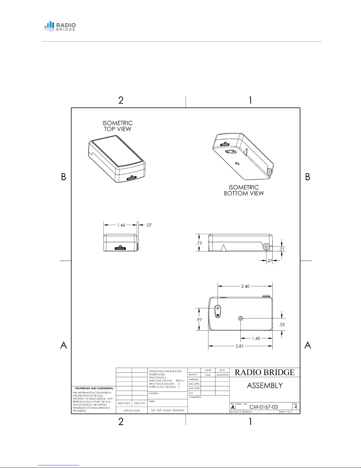
7. MECHANICAL DRAWINGS......................................................................................................... 9
8. REGULATORY.......................................................................................................................... 10
9. CUSTOMER SUPPORT ............................................................................................................. 10
10. DISCLAIMERS....................................................................................................................... 10
11. TRADEMARKS AND COPYRIGHT........................................................................................... 10

WIRELESS WATER SENSOR
COPYRIGHT ©2018, RADIO BRIDGE INC.WIRELESS WATER SENSOR PAGE 2OF 10
1. QUICK START
To start using your sensor, simply go to:
https://console.radiobridge.com
From here you can register your device and immediately start receiving messages from the
sensor.
The sensor configuration, message monitoring, and setting up alerts is usually self-explanatory
through the user interface. For further explanations of any sensor features, you may refer to this
user guide.
2. OVERVIEW
2.1. Sensor Overview
The wireless sensors designed and manufactured by Radio Bridge provide full sensor to cloud
solutions for Internet of Things (IoT) applications. The water sensor uses a water/liquid sensor
probe to detect the presence of water or other liquids. When the presence of water or
another liquid is detected, an alert is sent over the wireless network. Versions of the sensor
support the major LPWAN standards such as Sigfox, LoRa/LoRaWAN, and SubGig.
Features include:
•Built-in radio that talks directly with the wireless network. Standards include:
oSigfox
oLoRa/LoRaWAN
oSubGig®
•Two types of tamper detection: enclosure tamper and wall mount tamper
oEnclosure tamper detects if the packaging of the sensor itself is opened or broken
oWall mount tamper detects if the sensor has been removed from the wall or
mounting point
•20,000-1M+ transmissions on a single battery and a 5-10 year battery life depending on
usage (see Battery section)
•Fully integrated internal antenna
•Over the air sensor configuration in the field
•Automatic low battery reporting and supervisory messages

WIRELESS WATER SENSOR
COPYRIGHT ©2018, RADIO BRIDGE INC.WIRELESS WATER SENSOR PAGE 3OF 10
2.2. Revision History
Table 1 Revision History
Revision
Date
Description
1.0
April 2018
Initial release of the document
1.1
August 2018
Updated protocol definitions
1.2
October 2018
Regulatory and FCC
2.3. Document Conventions
Table 2 Document Conventions
Font / Icon
Meaning
Important notes
Warnings and cautions
2.4. Part Numbers
Table 3 Part Numbers
Part Number
Wireless Standard
Region
RBS101-WAT-RCZ2
Sigfox
North America
RBS201-WAT-315
SubGig
North America
RBS301-WAT-US
LoRa
North America

WIRELESS WATER SENSOR
COPYRIGHT ©2018, RADIO BRIDGE INC.WIRELESS WATER SENSOR PAGE 4OF 10
3. TECHNICAL SPECIFICATIONS
3.1. Absolute Maximum Ratings
Table 4 Absolute Maximum Ratings
Parameter
Rating
Units
Operating ambient temperature
-30 to +70
°C
Storage ambient temperature
-40 to +100
°C
4. BATTERY LIFE
The sensor uses a lithium non-rechargeable battery and is capable of 20,000 to 1,000,000+ total
messages depending on the wireless standard and usage. For an accurate estimate of battery life,
please refer to the “Sensor Battery Estimator.xlsx” spreadsheet on the Radio Bridge website. This
spreadsheet combines usage information such as average number of messages per day and
estimates the battery life for a particular sensor.
The power required for a message transmission is much greater than the “sleep current” (the
power consumed when the sensor is inactive) for high power radio technologies such as Sigfox
and LoRaWAN. This means that the battery life for most sensors is primarily dependent on the
number of transmissions per day.
Different battery types will deplete over time with different voltage profiles. For instance, a
lithium battery will maintain a relatively high voltage for the life of the battery and then
experience a rapid drop near the end, whereas an alkaline battery will experience a more gradual
reduction in voltage over time. Radio Bridge sensors are shipped with lithium batteries, and these
are recommended when the battery needs to be eventually replaced.
Refer to the spreadsheet “Sensor Battery Estimator.xlsx” on the Radio Bridge
website for specific battery life estimates.

WIRELESS WATER SENSOR
COPYRIGHT ©2018, RADIO BRIDGE INC.WIRELESS WATER SENSOR PAGE 5OF 10
Temperature also plays a role in battery life. The battery life estimates in the online spreadsheet
assume room temperature, but temperatures close to the maximum and minimum ratings will
have a negative impact on battery life. For example, battery voltage tends to be lower in cold
temperatures and the internal circuitry needs a certain minimum voltage to operate properly
before it will shut down. Thus, battery life will tend to be shorter when running the sensor in cold
environments.
The battery voltage is reported by the supervisory messages as well as a low battery indicator.
See the section on Message Protocol for more detail.
5. TEST MESSAGES
The sensor can be triggered to send test messages by placing a magnet next to the triangular
notch on the side of the sensor. There is a smallmagnetic reed switch that will detect the presence
of a magnet and send a message. This can be used for diagnostic purposes to ensure the sensor
is within range and connected to the network.
6. MESSAGE PROTOCOL
This section defines the protocol and message definitions for the sensor.
If the standard Radio Bridge console (console.radiobridge.com) is not used, refer to this section
to decode the sensor data and configure the sensor through downlink messages.
Radio Bridge provides a web-based console at console.radiobridge.com
to configure and monitor sensors. Usage of this console is highly
recommended for most customers rather than implementing the
protocols defined in this section.
Battery voltage will be lower in cold temperatures and thus battery life
will be reduced in cold environments.

WIRELESS WATER SENSOR
COPYRIGHT ©2018, RADIO BRIDGE INC.WIRELESS WATER SENSOR PAGE 6OF 10
6.1. Common Messages
There are common messages across all wireless sensors that are defined in the document
“Common Sensor Messages” which is available on the Radio Bridge website.
Common messages include basic error messages, tamper, supervisory, and downlink ack. It
is important to refer to that document prior to decoding the messages defined in this
section.
Refer to the document “Common Sensor Messages” for definitions of all
common messages. Common messages are not defined in this document.

WIRELESS WATER SENSOR
COPYRIGHT ©2018, RADIO BRIDGE INC.WIRELESS WATER SENSOR PAGE 7OF 10
6.2. Uplink Messages
The uplink message (sensor to web application) specific to the sensor is defined in following
table. The common uplink messages are not included in this section (see common messages
document).
Table 5 Uplink Message 0x08: Water or Liquid Event
Byte
Description
0
Water event (see table Water Event Bit Definitions)
1
Relative measurement of the resistance between probes
(scale of 0-255)
The water event bit definitions are shown in the following table.
Table 6 Water Event Bit Definitions
Bits
Description
7:2
Unused
1
Water or liquid not present
0
Water or liquid present
The 8-bit event for the liquid sensor contains a relative measurement of the resistance
between the probes with a scale of 0-255. Different liquids will have a different resistance
through the material (water vs fuel for example), so this measurement can be used to set the
threshold properly as defined by the configuration message in the Downlink section

WIRELESS WATER SENSOR
COPYRIGHT ©2018, RADIO BRIDGE INC.WIRELESS WATER SENSOR PAGE 8OF 10
6.3. Downlink Messages
The downlink message (web application to sensor) specific to the sensor configuration is
defined in following table. The common downlink messages are not included in this section
(see common messages document).
Table 7 Downlink Configuration Message 0x08
Byte
Description
0
Disable Events (see table Disable Events Bit Definitions)
1
Threshold of relative resistance between probes (scale 0-255)
2
Restoral margin in units of relative resistance between probes
(scale 0-255)
The downlink configuration message for the sensor contains the resistance threshold for
detecting the presence of a liquid. Different liquids will have difference resistance, so this
threshold will need to be set based on the type of liquid that is being detected. The payload
from the event message can be used to find the relative resistance of a given liquid.
The bit definitions for the disable events field are defined below.
Table 8 Disable Events Bit Definitions
Byte
Description
7:2
Not used
1
Disable water not present message (1 to disable, 0 to enable)
0
Disable water present message (1 to disable, 0 to enable)
An alert is sent when the relative measurement increases above the defined threshold. The
restoral margin requires that the measurement reduces by a certain amount below the
threshold before another alert is triggered. Both the threshold and restoral margin are in
units of relative resistance measurements on a scale of 0-255.

WIRELESS WATER SENSOR
COPYRIGHT ©2018, RADIO BRIDGE INC.WIRELESS WATER SENSOR PAGE 9OF 10
7. MECHANICAL DRAWINGS
The mechanical drawings provided in this section are for the main body of the sensor. All
dimensions are inches unless otherwise noted.

WIRELESS WATER SENSOR
COPYRIGHT ©2018, RADIO BRIDGE INC.WIRELESS WATER SENSOR PAGE 10 OF 10
8. REGULATORY
Per FCC 15.19(a)(3) and (a)(4) This device complies with part 15 of the FCC Rules. Operation is
subject to the following two conditions: (1) This device may not cause harmful interference, and
(2) this device must accept any interference received, including interference that may cause
undesired operation.
Per FCC 15.21, Changes or modifications not expressly approved by Radio Bridge could void
authority to operate the devices.
(Sigfox) FCC ID: 2APNUSFM10R2
(LoRa) FCC ID: 2APNUCMABZ
9. CUSTOMER SUPPORT
Radio Bridge offers free technical support at:
https://support.radiobridge.com
Radio Bridge also offers technical support plans and service packages to help our customers get
the most out of their Radio Bridge products.
10. DISCLAIMERS
Information in this document is subject to change without notice and does not
represent a commitment on the part of Radio Bridge. Radio Bridge provides this
document “as is,” without warranty of any kind, expressed or implied, including, but not
limited to, the implied warranties of fitness or merchantability for a particular purpose.
Radio Bridge may make improvements and/or changes in this manual or in the
product(s) and/or the software described in this manual at any time.
11. TRADEMARKS AND COPYRIGHT
Radio Bridge™, SubGig®, and BridgeBee® are trademarks of Radio Bridge Inc in the United
States.
© 2018 Radio Bridge Inc. All rights reserved.
This manual suits for next models
2
Table of contents
Other Radio Bridge Accessories manuals

Radio Bridge
Radio Bridge RBS301-AL-US User manual

Radio Bridge
Radio Bridge RBS306-US10M-US User manual

Radio Bridge
Radio Bridge RBS301-WAT-US User manual

Radio Bridge
Radio Bridge RBS306-VM30-US User manual

Radio Bridge
Radio Bridge RBS101-AL-RCZ1 User manual

Radio Bridge
Radio Bridge RBS306-TILT-HP-US User manual
Popular Accessories manuals by other brands

CAPTELEC
CAPTELEC MASTER BLADES manual

Omega
Omega FTB300 Series user guide

Palram
Palram Lyra 1350 Twin Wall - Door Cover Assembly instructions

Lehner Versand
Lehner Versand ST6521-64 instruction manual

Expo Börse
Expo Börse 613-400224 instruction manual

PCB Piezotronics
PCB Piezotronics IMI SENSORS 641B71 Installation and operating manual