Tekmar 542 User manual

1 of 8 © 2008 W 542 - 12/08
W542
12/08
tekmarNet®4 Thermostat 542
- Wiring Brochure
Overview
Information
Brochure
Choose controls
to match
application
1Application
Brochure
Design your
mechanical
applications
2Layout
Brochure
Rough-in
wiring
instructions
3Wiring
Brochure
Wiring and
installation of
specific control
4Job
Record
Record settings &
wiring details for
future reference
6
Data
Brochure
Control settings
and sequence of
operation
5
The following brochure describes how to wire the tekmar tekmarNet®4 (tN4) thermostat 542. The 542 has outputs for one
heat stage. The 542 has inputs for two auxiliary sensors. The wiring of 542 thermostat is simple and cost effective.
Table of Contents:
Definitions.......................................................................2
Rough-In Wiring .............................................................2
Remove the Wiring Cover ..............................................3
Mounting the Thermostat ...............................................3
Wiring Symbols...............................................................3
Electrical Drawings ......................................................3-5
Wiring the Thermostat ....................................................6
Troubleshooting the Wiring .............................................7
Testing the Wiring...........................................................7
Technical Data................................................................8
Auxiliary
Sensors
1st Stage
Heating
DIP
Switches
tN4
Network
24 V (ac)
Power

© 2008 W 542 - 12/08 2 of 8
Definitions
The following defined terms and symbols are used throughout this manual to bring attention to the presence of hazards of
various risk levels, or to important information concerning the life of the product.
– Caution: Refer to accompanying documents.
INSTALLATION
CATEGORY II – Local level appliances.
Caution
Improper installation and operation of this control could result
in damage to the equipment and possibly even personal
injury or death. It is your responsibility to ensure that this
control is safely installed according to all applicable codes
and standards. This electronic control is not intended for
uses as a primary limit control. Other controls that are
Choose the placement of the thermostats early in the
construction process to enable proper wiring during
rough-in.
Consider the following:
•
Interior Wall.
•
Keep dry. Avoid potential leakage onto the control.
RH 80% to 88°F (31°C), down to 50% from 104 to
122°F (40 to 50°C). Non-condensing environment.
•
No exposure to extreme temperatures beyond 32 - 122°F
(0 - 50°C).
Rough-In Wiring
Sensor 2
Sensor 1
2 Cond. / 18 AWG
2 Cond. / 18 AWG
4 Cond. / 18 AWG
Note: When multiple wires
run to the same equipment
location, wiring conductors
can share one wire jacket.
1st Stage Heat
24 V (ac) Power
tN4 Network
Zone Manager
•
No draft, direct sun, or other cause for inaccurate
temperature readings.
•
Away from equipment, appliances, or other sources of
electrical interference.
•
Easy access for wiring, viewing, and adjusting the
display screen.
•
Approximately 5 ft. (1.5 m) off the finished floor.
Use standard 18 AWG wire for the thermostat power, stages
tN4 and sensor connections.
Refer to the diagram below to determine the number of
conductors to run from each piece of equipment to the
thermostat location.
intended and certified as safety limits must be placed into
the control circuit. Do not attempt to service the control.
Refer to qualified personnel for servicing. There are no
user serviceable parts. Attempting to do so voids warranty
and could result in damage to the equipment and possibly
even personal injury or death.

3 of 8 © 2008 W 542 - 12/08
Mounting the Thermostat
If a single gang switch box is used, an Adaptor Plate 007
is required to mount the thermostat to the box.
•
Fasten the base of the thermostat to the adaptor plate.
•
Feed the wiring through the openings in the back of the
adaptor plate and thermostat.
•
Use the upper and lower screw holes to fasten the
adaptor plate to the box.
Remove the Wiring Cover:
To remove the wiring cover:
•
Place a small slot screwdriver or similar tool into the slot
located on the top of the thermostat.
•
While pushing against the plastic tab, pull the top of the
front cover so that it pivots around the bottom edge of
the thermostat’s base.
The electrical drawing examples on the following
pages show the 542 in common applications. Choose
the drawing that most accurately depicts the components
in your system and use that drawing as a guide to aid in
wiring your system.
These are only concept drawings, not engineered drawings.
They are not intended to describe a complete system nor
any particular system. It is up to the system designer to
Electrical Drawings
OR
Wiring Symbols
Dry contact switch. Operates a device.
Do not apply power to these terminals.
Serious control damage will result.
Powered switch. 24 V (ac), switched
output to valve, pump relay etc. tekmarNet®4
Factory jumper.
If a switch box was not used, mount the thermostat directly
to the wall.
•
Feed the wiring through the openings in the back of the
thermostat.
•
Use screws in the screw holes to fasten the thermostat
to the wall. At least one of the screws should enter a
wall stud or similar rigid material.
determine the necessary components for and configuration
of the particular system being designed including additional
equipment isolation relays (for loads greater than the
controls specified output ratings) and any safety devices
which in the judgement of the designer are appropriate in
order to properly size, configure and design that system
and to ensure compliance with building and safety code
requirements.
Stud
Switch
Box
Thermostat
Base
007 Adaptor
Plate
Thermostat 31/4”
(83 mm)
Stud
23/8”
(60 mm)
screwhole
23/8”
(60 mm)
screwhole
Thermostat
Thermostat
Base
Wall
Mounted on wallboardMounted on switch box
Menu
Item
Remove cover
Push tab
1
2

© 2008 W 542 - 12/08 4 of 8
Electrical Application 542 E1
Description:
One Stage Heating (H1= Radiant).
Legend:
Sensor 1 = Floor
Sensor 2 = Outdoor
Outdoor Sensor
070
tN4 C RW
Slab Sensor
079
Zone Managers
Factory installed jumper
connects R to Rh
(terminals 3 to 4) To
isolate W relay,
cut jumper
542 tNt

5 of 8 © 2008 W 542 - 12/08
Electrical Application 542 E2
Description:
One Stage Heating (H1= Fin-tube Convector).
Legend:
Sensor 1 = Remote
Sensor 2 = Room
Factory installed jumper
connects R to Rh
(terminals 3 to 4) To
isolate W relay,
cut jumper External Class 2
Transformer
24 V (ac)
R C
Universal
Sensor 071
Other tN4 Thermostat
or Zone Manager
Indoor Sensor
076
542 tNt

© 2008 W 542 - 12/08 6 of 8
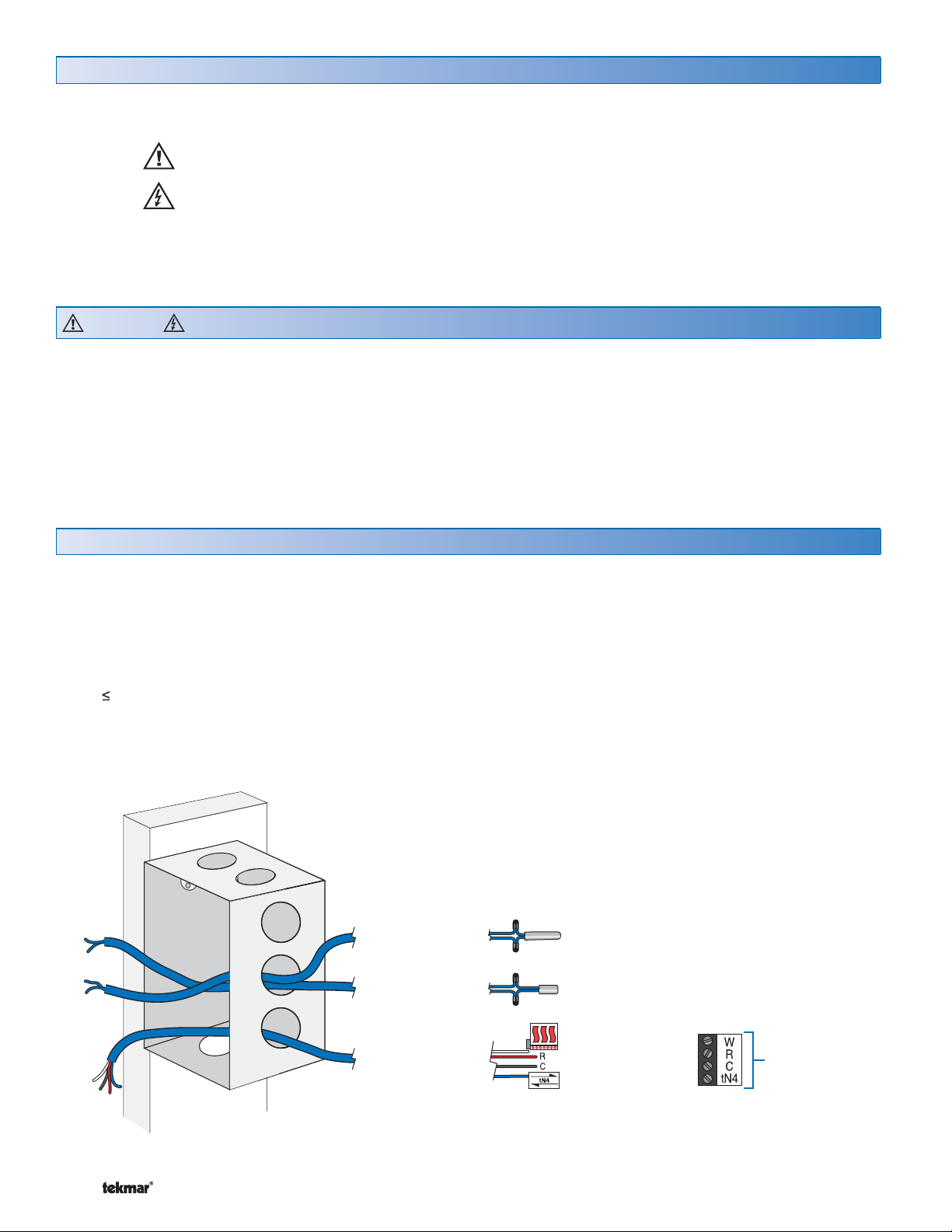
Wire the tN4 communication to terminals tN4 and C.
If a Zone Manager is used:
•
Connect the tN4 on the thermostat to the tN4 on the
proper zone of the Zone Manager used for the first stage
of heat. The C terminal is already connected.
If a Zone Manager is not used:
•
Connect the tN4 on the thermostat to the tN4 on another
tN4 device on the same tN4 bus.
•
Connect the C on the thermostat to the C terminal on
another tN4 device on the same tN4 bus.
tN4 Communication Terminals 1, 2
Wire the first stage of heating to the Heat 1 Relay.
(Rh - W)
•
Use these terminals as a switch to operate the first stage
of heating.
If a Zone Manager is used:
•
Connect W on the thermostat to W on the proper zone
of the Zone Manager.
If a Zone Manager is not used:
•
Determine if the factory jumper must be cut.
•
When the factory jumper is not cut, W is a powered
output that is internally connected to R.
•
When the factory jumper is cut, Rh W is an isolated
switch. No power is available from these terminals.
Heat 1 Relay Terminals 3 - 5
Wire 24V (ac) to terminals C and R.
If a Zone Manager is used:
•
Connect C on the thermostat to C on the proper zone
of the Zone Manager.
•
Connect R on the thermostat to R on the proper zone
of the Zone Manager.
If a 24 V(ac) transformer is used:
•
Connect C on the thermostat to C on the transformer.
•
Connect R on the thermostat to R on the transformer.
Power (24 V (ac)) Terminals 2, 3
Note: This connection is polarity sensitive.
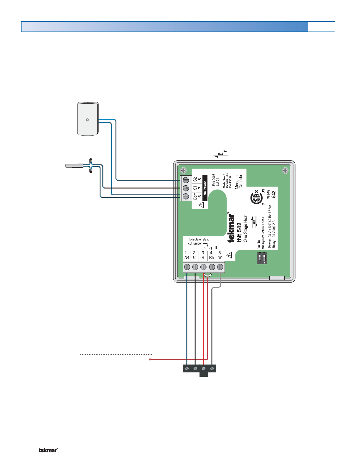
Wiring the Thermostat:
The auxiliary sensors are connected to the thermostat on
terminals Com, S1 and S2.
•
• Connect sensor 1 to terminals S1 and Com.
•
• Connect sensor 2 to terminals S2 and Com.
Do not apply power to terminals 6 - 8, permanent
damage to the sensors and/ or thermostat will result!
Auxiliary Sensors Terminals 6 - 8
Do Not Apply Power
Thermostat
Universal
Sensor
Outdoor
Sensor
To various tekmar
sensors
8S2
7S1
6Com
tN4 C RW
Thermostat
Zone Manager
tN4 C R Rh W
12345
Thermostat
Zone Manager
or other tN4
thermostat
tN4 C R Rh W
12345
tN4 C RW
*Factory installed jumper
connects terminals R to Rh
(to isolate W relay, cut jumper)
Thermostat
Zone Manager
tN4 C R Rh W
12345
tN4 C RW

7 of 8 © 2008 W 542 - 12/08
Troubleshooting the Wiring
The following tests are to be performed using standard
testing practices and procedures and should only be carried
out by properly trained and experienced persons.
A good quality electrical test meter, capable of reading
from at least 0 - 300 V (ac), 0 - 2,000,000 Ohms, and testing
for continuity is essential to properly test the wiring and
sensors.
General
Testing the Wiring
Testing 24 V (ac) Power Supply
1. Remove the front cover from the thermostat.
2. Use an electrical test meter to measure (ac) voltage between the R and C terminals. The reading should be 24V (ac)
+/– 10%.
3. Install the front cover.
1. Remove the front cover from the thermostat.
2. Disconnect the wires from the relay that is to be
tested.
3. Use an electrical test meter and check for continuity
across the relay.
•
• When the relay’s symbol is displayed in the LCD,
there should be continuity.
•
• When the relay’s symbol is not displayed in the
LCD, there should be no continuity.
4. Reconnect the wires to the relay.
5. Install the front cover on the thermostat.
542 LCD Display Segments
Heat 1
Testing the Relays
To test the sensors, the actual temperature at each sensor
location must be measured.
Use a good quality digital thermometer with a surface
temperature probe for ease of use and accuracy. Where
a digital thermometer is not available, place a spare
sensor alongside the one to be tested and compare
the readings.
Testing the Sensors
1. Remove the front cover from the thermostat.
2. Disconnect the wires from the sensor that is to be
tested.
3. Test the sensor’s resistance according to the instructions
in the sensor Data Brochure D070, D 074 or D079.
4. Reconnect the wires.
5. Install the front cover on the thermostat.
To test the tN4 Network, check the wires for continuity.
1. Remove the front cover from the thermostat.
2. Disconnect the two wires (tN4 and C) at one end and
connect them together.
Testing the tN4 Network
3. Go to the other end of the wires and disconnect them.
4. Using an electrical test meter, check for continuity.
5. Reconnect the wires.
6. Install the front cover on the thermostat.
tN4 C R Rh W
12345
8S2
7S1
6Com
###

tekmar Control Systems Ltd., Canada
tekmar Control Systems, Inc., U.S.A.
Head Office: 5100 Silver Star Road
Vernon, B.C. Canada V1B 3K4
(250) 545-7749 Fax. (250) 545-0650
Web Site: www.tekmarcontrols.com
Product design, software and literature are Copyright © 2008 by:
tekmar Control Systems Ltd. and tekmar Control Systems, Inc. 8 of 8 All specifications are subject to change without notice.
Printed in Canada. W542 - 12/08.
Technical Data:
tekmarNet®4 Thermostat 542: One Stage Heat
Control Microprocessor PID control; This is not a safety (limit) control
Packaged weight 0.46 lb. (210 g)
Enclosure White PVC plastic
Dimensions 2-7/8” H x 2-7/8” W x 13/16” D (73 x 73 x 21 mm)
Approvals CSA C US, CSA/UL 61010-1, meets Class B: ICES and FCC Part 15
Ambient conditions Indoor use only, 32 to 122°F (0 to 50°C)
RH 80% to 88°F (31°C), down to 50% from 104 to 122°F (40 to 50°C)
Altitude <6560 feet (2000 m), Installation Category II, Pollution Degree 2
Power supply 24 V(ac) ± 10% 60 Hz, 1.6 VA, NEC / CEC Class 2
W1 Relay 24 V(ac) 2 A
Sensors: NTC thermistor, 10 k @ 77°F (25°C ± 0.2°C) ß = 3892
– Included None
– Optional tekmar type # 071, 070, 072, 073, 076, 077, 078, 079, 082, 084
Technical Data
The installer must ensure that this control and its wiring are isolated and/ or shielded from strong sources of electromag-
netic noise. Conversely, this Class B digital apparatus complies with Part 15 of the FCC Rules and meets all requirements
of the Canadian Interference-Causing Equipment Regulations. However, if this control does cause harmful interference to
radio or television reception, which is determined by turning the control off and on, the user is encouraged to try to correct
the interference by re-orientating or relocating the receiving antenna, relocating the receiver with respect to this control,
and /or connecting the control to a different circuit from that to which the receiver is connected.
Cet appareil numérique de la classe B respecte toutes les exigences du Règlement sur le matériel brouilleur du Canada.
This manual suits for next models
1
Table of contents
Other Tekmar Thermostat manuals

Tekmar
Tekmar tekmarNet 4 User manual

Tekmar
Tekmar tekmarNet 2 Thermostat 529 User manual

Tekmar
Tekmar tekmarNet 532 User manual

Tekmar
Tekmar 508 User manual

Tekmar
Tekmar tekmarNet 532 User manual

Tekmar
Tekmar 518 User manual

Tekmar
Tekmar tekmarNet 4 537 User manual

Tekmar
Tekmar 527 User manual

Tekmar
Tekmar tekmarNet 553 User manual

Tekmar
Tekmar D 508 User manual

Tekmar
Tekmar 510 User manual

Tekmar
Tekmar 561 User manual

Tekmar
Tekmar 519 User manual

Tekmar
Tekmar Invita User manual

Tekmar
Tekmar tekmarNet 553 User manual

Tekmar
Tekmar D528 User manual

Tekmar
Tekmar 561 User manual

Tekmar
Tekmar 545 tekmarNet 4 User manual

Tekmar
Tekmar tNt 540 User manual

Tekmar
Tekmar 511 User manual