TEKNA DPG601 Manual

РУКОВОДСТВО ПО ЭКСПЛУАТАЦИИ
TEKNA DPG
(cod. EM00136004)
Электромагнитный дозирующий насос
пропорционального типа с цифровым управлением

РЕКОМЕНДАЦИИ ПО УСТАНОВКЕ И ЗАПУСКУ НАСОСА
TEKNA серии DPG
ВНИМАНИЕ: ПЕРЕД ИСПОЛЬЗОВАНИЕМ ИЗДЕЛИЯ, ОБРАТИТЕ ВНИМАНИЕ НА ДАННЫЕ,
ПРИВЕДЕННЫЕ НА ЭТИКЕТКЕ.
Образец:
TEKNA
400 Spm
Type
bars
l/hr
Gph
Psi
DPG902
230VAC
50/60 Hz
40 W
Fuse 2 A L
10
10
2.64
145
6
12
3.17
87
2
15
3.96
29
Code DPG902ASP0000 Serial n° xxxxxxx
ТАБЛИЦА ДЛЯ ВЫБОРА МОДЕЛИ ИЗДЕЛИЯ:
DPG601
12
1.5
0.06
4 / 6 400 1.7
10
2
0.08
6
2.5
0.10
DPG602
8
5
0.21
4 / 6 400 1.7
5
6
0.25
1
9
0.38
DPG901
16
6
0.25
4 / 6 400 3.1
14
7
0.29
12
8
0.33
DPG902
10
10
0.42
4 / 6 400 3.1
6
12
0.50
2
15
0.63
DPG903
5
25
1.04
8 / 12 400 3.2
4
40
1.67
3
50
2,08
DPG904
2
60
2.50
8 / 12 400 3.2
1
80
3.33
0
100
4.17
Модель
Давление
Производительность
Объем дозируемой
жидкости за впрыск
Соединительный
размер
Кол-во
впрысков/мин
Вес
атм
л/час
Вход /Выход
кг
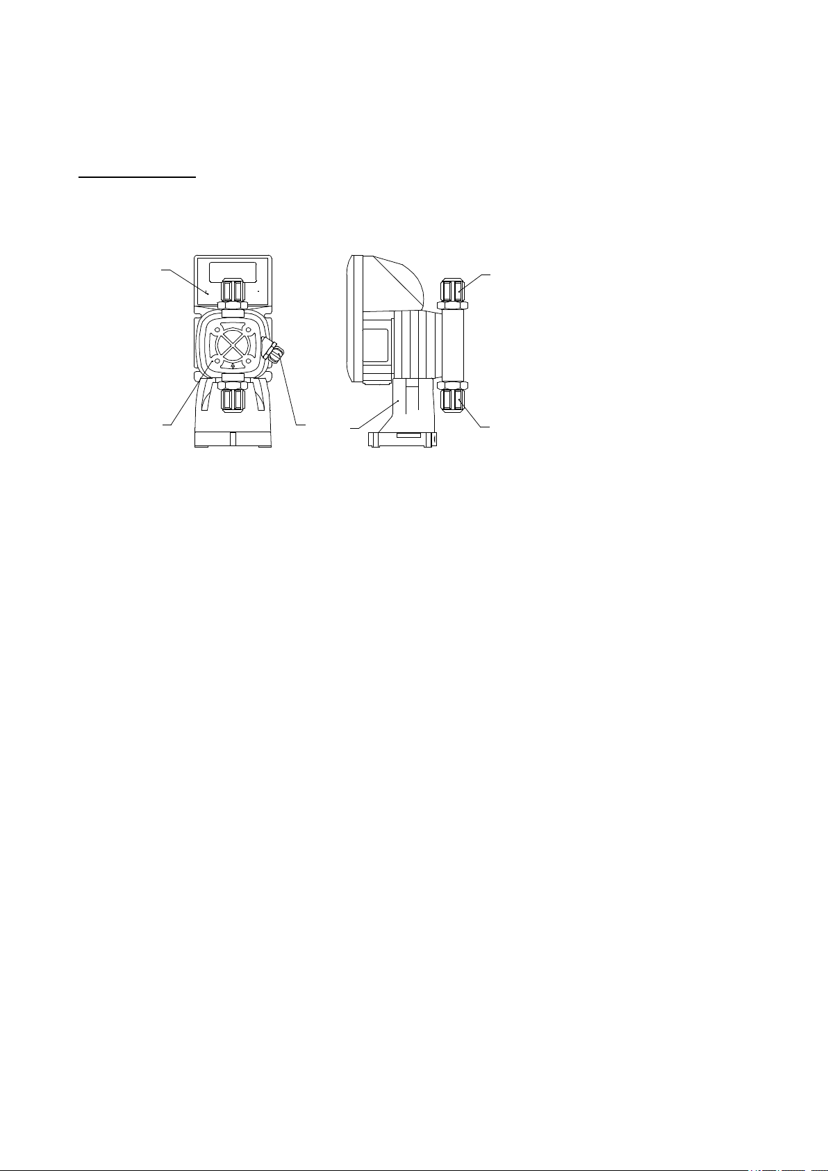
ВВОДНАЯ ЧАСТЬ
Изделие представляет собой электромагнитный механизм, управляемый при помощи внутренней электрической цепи,
и гидравлической части.
23
14
65
1 Панель управления
2 Гидравлическая часть (головка
насоса)
3 Клапан выпуска воздуха
4 Выходной фитинг (подача)
5 Входной фитинг (всасывание)
6 Кронштейн крепления изделия
к емкости.
Части изделия, контактирующие с дозируемой жидкостью, изготовлены из материала стойкого к
химическому воздействию большей части, используемых в природе химических элементов. Однако, перед
эксплуатацией изделия, настоятельно рекомендуется проконсультироваться с производителем или его
представителем, относительно химической совместимости дозируемой жидкости (химиката) с изделием.
Стойкость материалов к химическому воздействию, зависит от множества факторов, и главным образом,
от условий эксплуатации. Необходимо учесть, что агрессивность химического раствора отлична от
агрессивности входящих в него, отдельных компонентов, и в некоторых случаях, предоставляя
информацию о химической совместимости материалов, производитель не гарантирует положительного
результата. При малейших сомнениях, рекомендуется произвести предварительные тесты.
Компоненты гидравлической части и их материалы
Головка насоса: PP (полипропилен)
Коннекторы: PP (полипропилен)
Диафрагма: PTFE (тефлон)
Сферические клапаны: PYREX (стекло теплостойкое промышленное)
Комплектация изделия
В комплекте с изделием поставляются все аксессуары, необходимые для его монтажа.
-Всасывающий клапан с фильтром в сборе
-Клапан впрыскивания в сборе
-Всасывающая трубка (прозрачная)
-Подающая трубка (прозрачная)
-Трубка клапана выпуска воздуха (белая)
-Набор крепежных винтов
-Кронштейн крепления изделия к емкости
-Данное руководство по эксплуатации

Всасывающий клапан с
фильтром
Клапан впрыскивания
Трубки ( всасывание, подача,
клапана выпуска воздуха)
Преимущество кронштейна крепления изделия к емкости, состоит в том, что смонтировав раз изделие на поверхности
емкости, можно обслуживать его, избегая дальнейшего контакта с содержимым емкости.
ВНИМАНИЕ
Соблюдайте осторожность при использовании изделия.
МЕРЫ ПРЕДОСТОРОЖНОСТИ ПРИ УСТАНОВКЕ И ОБСЛУЖИВАНИИ ИЗДЕЛИЯ
-H2SO4 СЕРНАЯ КИСЛОТА
-Данное изделие было испытано с водой. При дозировании некоторых химикатов (на пример серная кислота),
возможна нежелательная реакция с остатками воды в гидравлической части изделия. Поэтому тщательно
высушите гидравлическую часть изделия (головку насоса, диафрагму). Для этого, изделие должно
предварительно проработать несколько минут «всухую» (без всасывания дозируемой жидкости), в режиме
максимальной производительности с опущенной вниз трубкой подачи, до момента когда из трубки не вытекут
последние капельки воды.
-Установите изделие в месте, где температура окружающей среды не превышает 40°C и относительная влажность
ниже 90%. Чтобы избежать повышения температуры внутри изделия, не устанавливайте его под прямыми
солнечными лучами. Корпус изделия достаточно водостойкий и пылеотпорный, что позволяет использовать его
вне помещения. Не погружайте изделие в воду.
-Установите изделие в месте, удобном для его дальнейшего обслуживания. Хорошо укрепите изделие, во
избежание вибрации.
-Удостоверьтесь, что напряжение питающей электрической сети, соответствует значению, указанному на этикетке
изделия.
-ВНИМАНИЕ: ПЕРЕД ВЫПОЛНЕНИЕМ КАКИХ ЛИБО РАБОТ ПО РЕМОНТУ ИЛИ
ОБСЛУЖИВАНИЮ ИЗДЕЛИЯ, УБЕДИТЕСЬ, ЧТО ИЗДЕЛИЕ ОТСОЕДИНЕНО ОТ ВНЕШНЕЙ
ЭЛЕКТРИЧЕСКОЙ СЕТИ, ВСЕ КЛАПАНЫ ИЗДЕЛИЯ ЗАКРЫТЫ, А ТАКЖЕ СТРАВЛЕНО ВСЕ
ДАВЛЕНИЕ КАК ИЗ ИЗДЕЛИЯ, ТАК И ИЗ ПОДАЮЩЕЙ И ВСАСЫВАЮЩЕЙ МАГИСТРАЛИ.
-
- При обслуживании изделия, используйте защитную одежду, перчатки и защитные очки.
-При использовании изделия в системах под давлением, удостоверьтесь, что давление системы не превышает
максимально допустимого значения, приведенного на этикетке изделия.
МОНТАЖ
Изделие должно быть установлено в месте, где обеспечивается легкий доступ как к емкости с химикатом, так и к
точке его впрыскивания. Изделие имеет высокий класс защиты IP65 и поэтому, может эксплуатироваться вне
помещения.
-Установите изделие в месте, где температура окружающей среды не превышает 40°C и относительная влажность
ниже 90%. Чтобы избежать повышения температуры внутри изделия, не устанавливайте его под прямыми
солнечными лучами.
ЭЛЕКТРИЧЕСКАЯ ЧАСТЬ
Изделие должно быть подсоединено к внешнему источнику электрического питания, параметры которого
соответствуют данным, приведенным на этикетке изделия.
Насосы TEKNA не требуют заземления, так как в них используются компоненты с двойной электрической изоляцией
Внутренняя электрическая цепь изделия, спроектирована так, что позволяет выдерживать некоторые скачки
напряжения внешней питающей сети.
Не устанавливайте изделие вблизи электрического оборудования, вырабатывающего большое электрическое
напряжение.
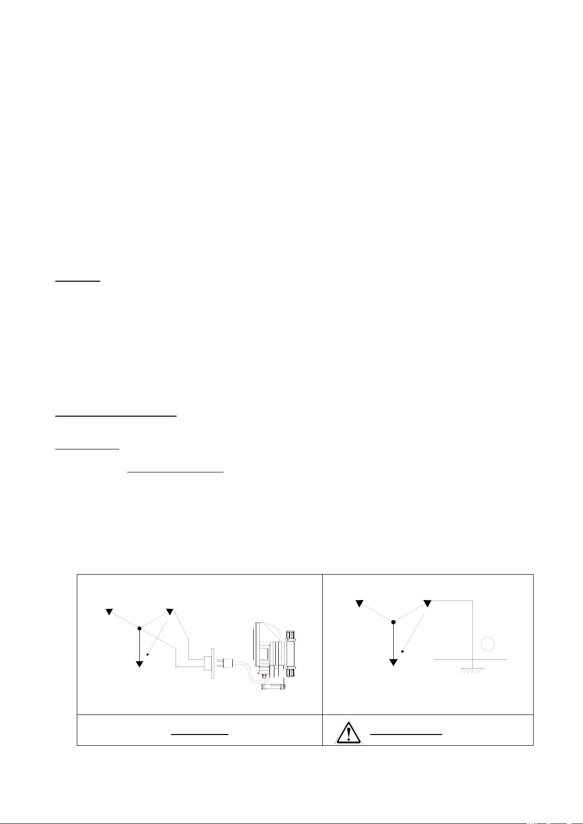
Если подключение питающего напряжения осуществляется от трехфазной сети 380 В, необходимо использовать
провода «+» и «0». Не используйте вместо провода «0» провод «земля».
RS
T
230 V
380 V
N
T
T
S
R
230 V
380 V
N
ПРАВИЛЬНО НЕ ПРАВИЛЬНО
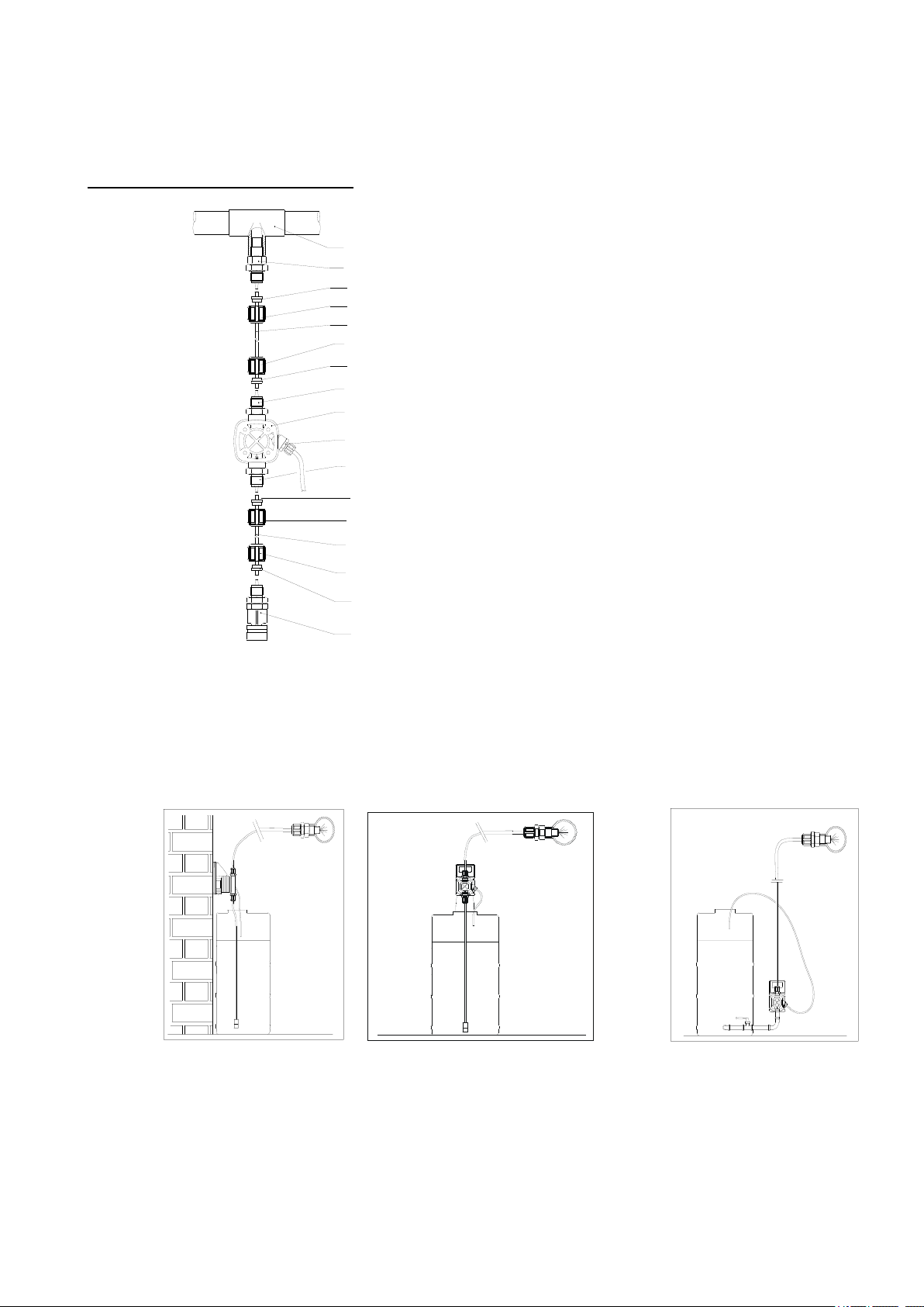
ГИДРАВЛИЧЕСКИЕ СОЕДИНЕНИЯ
1
2
3
4
5
6
7
8
9
10
11
9
10
10
9
9
10
1 Точка впрыскивания
2 Клапан впрыскивания
3 Прозрачная подающая трубка
4 Выпускной фитинг
5 Гидравлическая часть
6 Клапан выпуска воздуха
7 Всасывающий фитинг
8 Прозрачная всасывающая трубка
9 Соединительный фитинг.
10 Соединительное кольцо
11 Всасывающий клапан с фильтром
ТИПОВОЙ МОНТАЖ
НА СТЕНУ
С ИСПОЛЬЗОВАНИЕМ КРОНШТЕЙНА
НИЖЕ УРОВНЯ ЖИДКОСТИ
Всасывающий клапан с фильтром должен быть обязательно установлен, во избежание засорения в
гидравлической части изделия. Установите всасывающий клапан с фильтром на уровне 5-10 см от дна
емкости с дозируемым химикатом, чтобы предохранить забивание фильтра механическими загрязнениями,
осевшими на дне емкости.
Монтаж ниже уровня жидкости является наиболее предпочтительным, так как обеспечиваются
оптимальные условия для всасывания дозируемой жидкости изделием. Этот тип монтажа рекомендован
для насосов с низкой производительностью и при использовании химикатов, подверженных образованию
воздушных пузырей.

Используйте для соединений, прилагаемые трубки. В случае, если потребуются более длинные трубки,
убедитесь, что новые трубки имеют те же параметры (ID и OD), что и в комплекте поставки.
Если трубка клапана выпуска воздуха может быть подвергнута попаданию прямых солнечных лучей,
вместо поставляемой белой трубки, рекомендуется использовать трубку черного цвета. Обратитесь за этим
к фирме-производителю или к ее представителю на месте.
Для обеспечения правильного дозирования, на линии подачи должен быть установлен впрыскивающий
клапан.
Впрыскивающий клапан поставляется в версии с удлинителем. Если удлинитель не нужен, осторожно
обрежьте его, как показано на рисунке.
ШАБЛОНЫ ДЛЯ КРЕПЛЕНИЯ
Монтажный кронштейн
TEKNA серии 600
TEKNA серии 900
ГАБАРИТНЫЕ РАЗМЕРЫ
TEKNA series 600
TEKNA series 900

WIRING CONNECTION
Power supply
1
Phase
2
Neutral
Relay repeat alarm (optional)
3 Normaly closed(NC)
NC= connectors nos. 3 + connectors nos. 5
NO= connectors nos. 4 + connectors nos. 5
4 Normaly open (NO)
5 Common (C)
6, 7
Not used
Level probe
8
level alarm with stopped pump connectors nos. 9 + connectors nos. 8
level alarm with pump not stopped connectors nos. 10 + connectors nos. 8
9 lev
10 preall
External Signal
11 -
Imput frequency signal (WATER METER PULSE SENDER) connectors nos.
12 + connectors nos. 11
Imput current signal connectors nos. 13 (pole +) + connectors nos. 11 (pole -)
12 +
13 +
6
4
3
1
2
9
8
10
7
5
13
12
11
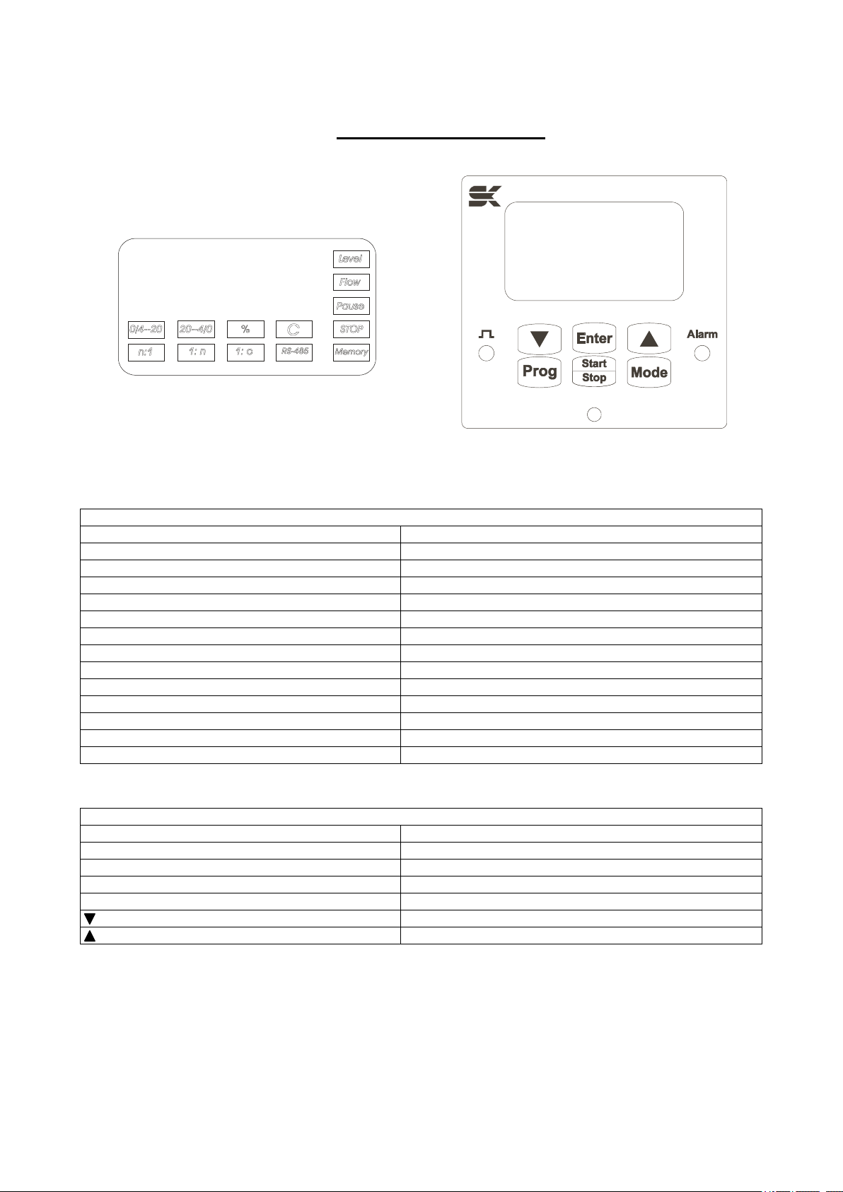
MONITORING PANEL
Fig 1: Display Fig 2: Pannello Comandi
DISPLAY
Icon
Functions of the pump
Level
Level alarm from a level control probe
Flow
Unavailable
Pause
Unavailable
Stop
Pump at standstill
Memory
Memory function
0/4—20
0/4—20 Mode
20—4/0
20—4/0 Mode
%
Indication of flow-rate value
C
Pump operate on is costant
n:1
n:1 Mode
1:n
1:n Mode
1:C
Unavailable
RS-485
Unavailable
KEYPAD
key
Functions of the pump
Prog
Programming
Start/Stop
Pump ON/OFF
Enter
To view the flow-rate that has been set
Mode
Flow-rate adjustment
Cursor for changing the setting
Cursor for changing the setting

TEKNA DPG
OPERATING PROCEDURES
The Tekna DPG pump is designed to operate either in CONSTANT MODE (continuous and constant dosing) or in
PROPORTIONAL MODE (dosing at a variable flow rate, depending on an outside signal).
For a better understanding of the functions and programming of the Tekna DPG pump, please see the programming diagram
provided on pages 17 to 19 and to Figures 1 and 2, showing the display and the control panel of the Tekna DPG.
STARTING UP THE PUMP
The pump factory settings are as follows:
-operating mode constant
-flow rate is displayed as percentage
-working frequency maximum (400 strokes/min)
-operation STOP
-"illuminated" icons STOP and C
MANUAL PRIMING
Start the pump pressing the START/STOP key ( STOP icon turns off). Press the and keys simultaneously. The
pump will start at the maximum frequency of 400 strokes a minute, If the keys are released, the pump will return to its previous
condition.
ADJUSTING THE FLOW RATE
To adjust the flow rate, press the Mode button and either the or the arrow to increase or decrease respectively the
flow rate value shown on the display, which is indicated as a percentage of the maximum flow rate.
The letter P will appear on the display, followed by the percentage value of the flow rate. While this is being shown, the %
icon is illuminated.
E.g. P 80 means that the pump is dosing a quantity equivalent to 80% of the quantity it would have dosed at the
maximum frequency, that it is to say it is dosing at a rate of 320 strokes/min.
The value varies from 100% (corresponding to 400 strokes/min) to 0% (0 strokes/min).
NOTE: 0% corrisponds to 1, 2, 3 strokes/min also. At 4 (or 5, 6 ,7) strokes/min the flow rate will be1%, and so on.
It is also possible to view the flow rate that has been set as a working frequency. To change the type of viewing from a
percentage of the maximum flow rate to the working frequency or vice versa, it is sufficient to keep the Mode key depressed
for at least 3 seconds; the display will change automatically.
The letter F will appear on the display together with the value that has been set in strokes per minute;
E.g.. F 350 means that the pump is dosing at a frequency of 350 strokes per minute.
The frequency varies from a maximum of 400 strokes/min (maximum flow rate) to a minimum of 0 stroke/min.(minimum flow
rate).
To adjust the flow rate press the Mode button and either the or the arrow to increase or lower the value of the working
frequency.
NOTE: The flow rate is adjustable both with the pump at a standstill, when the Stop icon is illuminated, and during dosing.
CHECKING THE LEVEL OF THE LIQUID TO BE DOSED
To check the level of the liquid to be dosed, it is possible to use a model LEV-4 level probe (item n° 9900121051).
There are two modes of operation:
a) Connection of the level probe to connectors nos. 8 and 9 (see CONNECTION DIAGRAM).
When the liquid reaches the required level, the pump will stop. On the display the Level icon will light up and the Alarm
LED will light up.
b) Connection of the level probe to connectors nos. 8 and 10 (see CONNECTION DIAGRAM).
When the liquid reaches the required level, the pump will NOT BE STOPPED. On the display the Level icon will light
up and the Alarm LED will start to flash.
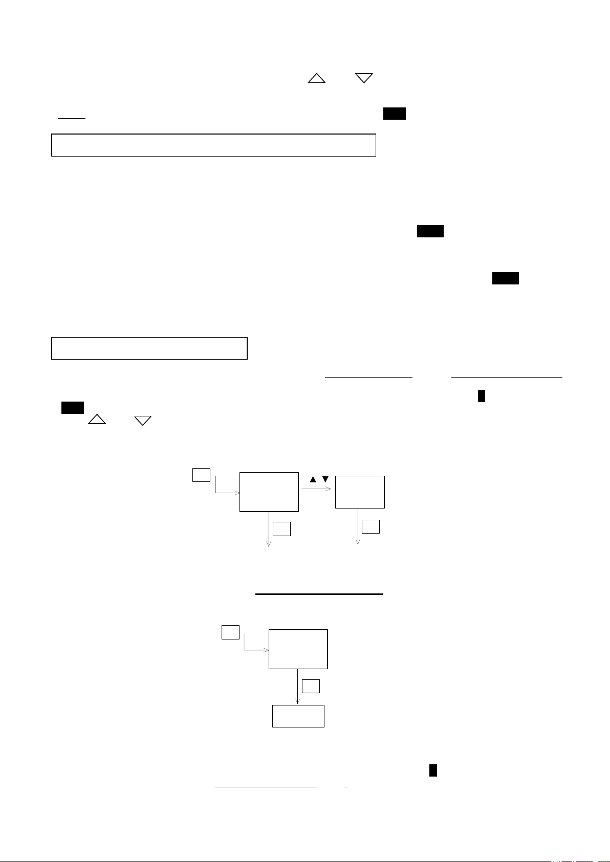
SELECTING THE MODE
The Tekna DPG pump has been designed to operate either in the CONSTANT MODE or in the PROPORTIONAL MODE.
To select the operating mode press the Prog key. The letter C will appear on the display, while the C icon will start to flash
(Stop icon illuminated).
Use the or arrows to select the required mode, P (proportional mode) or C (constant mode).
Press the Enter button to confirm the choice made.
CONSTANT MODE
Once the CONSTANT MODE has been chosen (see above) and has been confirmed by pressing the Enter button, the word
Prog will appear on the display for about one second. After this the value of the flow rate that has been set will be shown (for
adjustment and the type of displaying see the section on Adjustment of the flow rate). The C icon will remain illuminated.
In this mode the pump will carry out continuous and constant dosing at the flow rate that has been set (see Adjustment of the
flow rate).
C
Prog
Enter
P
Enter
C
Prog
Enter
Prog

The pump is started up and stopped manually by pressing the START/STOP button (the Stop icon will be off or illuminated
respectively).
WARNING: The pump may stop automatically if a pump-stop signal is given by the level probe (Level icon illuminated and
Alarm LED steady on), see the section on Checking the level of the liquid to be dosed.
PROPORTIONAL MODE
In this mode the pump doses at a variable flow rate depending on an an outside signal; It is possible to chose any of the
following options:
1. Mode 1:n. After each external pulse, for instance from a water-meter connected to the pump, the pump will dose “n”
strokes.
2. Mode n:1. After each “n” external pulses, for instance from a water-meter connected to the pump, the pump will dose 1
stroke
3. Mode 0/4—20. The pump will dose at a flow rate that is proportional to an input signal of the type 0/4-20 mA.
4. Mode 20—0/4. The pump will dose at a flow rate that is proportional to an input signal of the type 20-4/0 mA.
The succession of operations that are required to set the preferred mode is illustrated below. In the block
diagrams accompanying the various steps, the values that are shown on the display refer to the default
values.
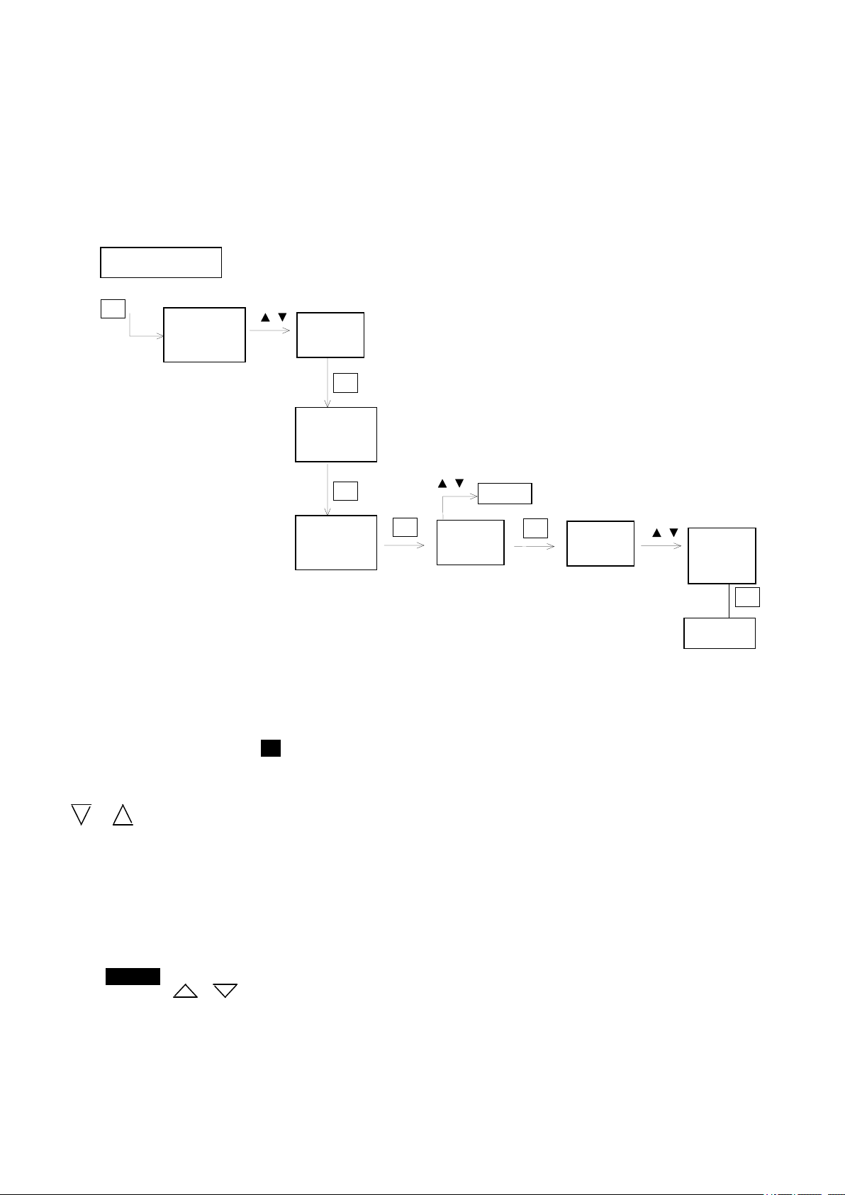
1) mode 1:n
This mode enables n strokes to be dosed for each pulse received from an outside source, for instance from a water-meter
able to send out pulses.
These strokes are dosed at the maximum working frequency (400 strokes/min).
Press the Prog button and select the PROPORTIONAL MODE (see Programming). On confirming the
PROPORTIONAL MODE by pressing the Enter key, mode 1.n is entered directly: the indication F 1.n will appear on
the display and the 1:n icon will flash.
If the Enter key is pressed, this mode is confirmed and the value of n will appear on the display. This refers to the
number of strokes the pump will provide for each pulse received. The or arrows can be used to increase or
decrease this value respectively.
C
Prog
P
Enter
F 1.n
Enter
4
Enter
OFF
On / OFF
Enter
0-9999
Prog

Example: If I have connected my pump to a water-meter of the CB1 range able to provide pulses (1 pulse/l), and I have
selected n=8, this will mean that for every pulse received from the water-meter my pump will provide 8 strokes. That is to
say, for each litre of water passing through the water-meter the pump will dose 8 strokes.
Once the value has been set, it must be confirmed by pressing the Enter key. Then it is possible to go on to set the
Memory function (see below).
The indication OFF (or ON) will appear on the display, to signal that the Memory function has been disabled (or
enabled). The Memory icon will flash.
The arrows keys or can be used to change the indication (ON or OFF).
MEMORY
This function consists of storing any external pulses in the event that the pump was not able to provide all the
programmed strokes. These pulses are stored by the microprocessor, up to a maximum of 65,535, and the “missing”
strokes are returned as soon as possible, for example when no more external signals are received by the pump
(example: no more water is running through the water-meter).
-Memory function set to OFF (Memory icon extinguished)
The pump does not store the excess pulses, however it does signal a situation of under- dosing, causing the display to
indicate ALL2. This will disappear as soon as the set parameters are reinstated.
-Memory function set to ON (Memory icon illuminated)
As soon as the pump starts to store the excess pulses, the Memory icon will start to flash, until all the corresponding
strokes have been returned.
If the storage capacity is exhausted (more than 65,535 pulses stored) the alarm will also be activated (the Memory
icon will continue to flash)
Dosing of the pulses that have been stored can be interrupted by pressing both the and keys at the same time.
Dosing of the pulses will then be resumed starting from the next incoming external signal (example: if the water starts
to run through the water-meter again).
WARNING: If the dosing pump is switched off, any pulses stored will be deleted.
Press Enter to confirm the selected settings and exit from programming. The indication Prog will appear on the display for
about one second, after which the value of previously set flow rate will appear.
To start the pump press the START/STOP button (the Stop icon will be extinguished). While the pump is working on the
display will appear the number of strokes the pump is dosing (count down).
WARNING: The pump may stop due to a possible pump-stopping signal given by the level probe (Level icon illuminated and
Alarm LED steady on). Please see the section on Checking the level of liquid to be dosed.
Please see the example on pag. 20
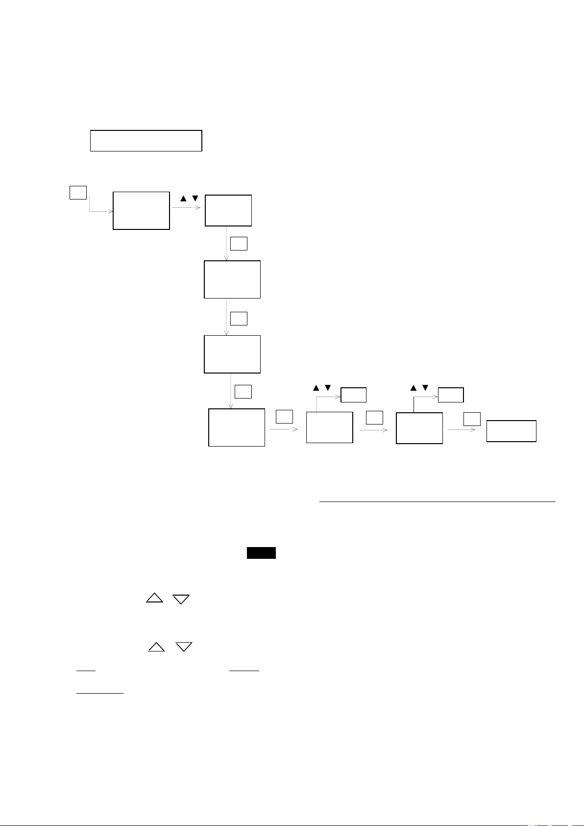
2) n:1 mode
This mode enables one stroke to be dosed for every n pulses received from an outside source, for example from a water-meter
capable of sending pulses.
Press the Prog button and select the PROPORTIONAL MODE (see Programming).
On pressing the Enter key and the Prog key (see diagram), the n:1 mode is entered directly and the indication F n.1 will
appear on the display while the n:1 icon will flash.
If the Enter key is pressed, this mode is confirmed and the value of n will appear on the display. This refers to the number of
impulses received by the pump from the outside source after which the pump will provide a stroke. The g or
arrows can be used to increase or decrease this value respectively.
Example: If I have connected my pump to a water-meter of the CB1 range able to provide pulses (1 pulse/L), and I have
selected n=8, this will mean that for every 8 pulses received from the water-meter my pump will provide 1 stroke. That is to
say, for every 8 litres of water passing through the water-meter the pump will dose 1 stroke.
Once the value has been set, it must be confirmed by pressing the Enter key. Then it is possible to go on to set the Memory
function (see below).
The indication OFF (or ON) will appear on the display, to signal that the Memory function has been disabled (or enabled).
The Memory icon will flash.
The arrows keys or can be used to change the indication (ON or OFF).
C
P
Enter
F 1.n
Enter
4
Enter
OFF
On / OFF
Prog
Prog
F n.1
Enter
0-9999
Prog

MEMORY
This function consists of storing any external pulses in the event that the pump was not able to provide all the
programmed strokes. These pulses are stored by the microprocessor, up to a maximum of 65,535, and the “missing”
strokes are returned as soon as possible, for example when no more external signals are received by the pump
(example: no more water is running through the water-meter).
-Memory function set to OFF (Memory icon extinguished)
The pump does not store the excess pulses, however it does signal a situation of under- dosing, causing the display to
indicate ALL2. This will disappear as soon as the set parameters are reinstated.
-Memory function set to ON (Memory icon illuminated)
As soon as the pump starts to store the excess pulses, the Memory icon will start to flash, until all the corresponding
strokes have been returned.
If the storage capacity is exhausted (more than 65,535 pulses stored) the alarm will also be activated (the Memory
icon will continue to flash)
Dosing of the pulses that have been stored can be interrupted by pressing both the and keys at the same time.
Dosing of the pulses will then be resumed starting from the next incoming external signal (example: if the water starts
to run through the water-meter again).
WARNING: If the dosing pump is switched off, any pulses stored will be deleted.
Press Enter to confirm the selected settings and exit from programming. The indication Prog will appear on the display for
about one second, after which the value of previously set flow rate will appear.
To start the pump press the START/STOP button (the Stop icon will be extinguished). While the pump is working on the
display will appear the number of pulses the pump is waiting for dose one stroke (count down).
WARNING: The pump may stop due to a possible pump-stopping signal given by the level probe (Level icon illuminated and
Alarm LED steady on). Please see the section on Checking the level of liquid to be dosed.
Please see the example on pag. 20
3) Mode: 0/4—20
In this mode the pump will dose at a flow rate that is proportional to an input signal of the type 0/4--20 mA.
It is possible to establish a current value at which the pump will dose at the minimum rate (0 stroke/min), and a current
rate at which the pump will dose at the maximum flow rate, equal to the value of the flow rate that we have established
(see the section on Adjustment of the flow rate).
Press the Prog button and select the PROPORTIONAL MODE (see Programming).
By pressing the Enter key once and the Prog key twice (see diagram), the 0/4—20 mode is entered directly and the
indication I will appear on the display. The 0/4--20 icon will start to flash.
By pressing the Enter key, this mode is “entered”, and the letter L will appear on the display together with the current
value at which the pump will dose at the minimum rate.
The arrows keys or can be used to increase or decrease this value.
If the Enter key is pressed again, the letter H will appear on the display, together with the current value at which the
pump will dose at the maximum flow rate.
The arrows keys or can be used to increase or decrease this value.
Note: The value of H must necessarily exceed the value of L.
WARNING: Having set first the value of L, the value of H can be set at a value 1 mA higher than L as a minimum.
Having set first the value of H, the value of L can be set at a value 1mA lower than H at a maximum.
Press Enter to confirm the settings and then exit from programming. The word Prog will appear on the display for about
one second, after which the value of the flow rate corresponding to the current signal received by the pump will be
displayed (as a frequency or as a % value, see the section on Adjustment of the flow rate).
C
P
Enter
F 1.n
Enter
L 4.0
Enter
H 20.0
Prog
Prog
F n.1
Prog
I
0-19
5-20
Enter
Prog

To start the pump press the START/STOP button (the Stop icon will be extinguished or illuminated respectively).
Note. If a current higher than the current value at which the pump doses at its maximum flow rate reaches the pump (e.g.:
current setting H = 10, current received = 15 mA), the pump will continue to dose at the maximum flow rate that has been
set, however the flow rate shown on the display will start to flash, indicating that the input current is higher than the value
that has been set.
Note. If a current lower than the current value at which the pump doses at its minimum flow rate reaches the pump (e.g.:
current setting L = 5, current received = 4 mA), the pump will no longer dose. Also, the flow rate shown on the display
will start to flash, indicating that the input current is lower than the value that has been set.
WARNING: The pump may stop due to a possible halt/stop allarm signal given by the level probe (Level icon
illuminated and Alarm LED steady on), see the section on Checking the level of the liquid to be dosed.
4) Mode: 20—4/0
In this mode, the pump will dose at a flow rate that is proportional to an input signal of the 20-4/0 mA type.
It is possible to establish a current value at which the pump will dose at the minimum rate (0 stroke/min), and a current
rate at which the pump will dose at the maximum flow rate, equal to the value of the flow rate that we have established
(see the section on Adjustment of the flow rate).
Press the Prog button and select the PROPORTIONAL MODE (see Programming).
By pressing the Enter key once and the Prog key three times (see diagram), the 20—4/0 mode will be entered directly
and the indication I will appear on the display. The 20--4/0 icon will start to flash.
By pressing the Enter key, this mode is “entered”, and the letter L will appear on the display together with the current
value at which the pump will dose at the minimum rate.
C
P
Enter
F 1.n
Enter
L 20.0
Enter
H 4.0
Prog
Prog
F n.1
Prog
I
20-5
0-19
Enter
Prog
I
Prog

The arrows keys or can be used to increase or decrease this value respectively.
If the Enter key is pressed again, the letter H will appear on the display, together with the current value at which the
pump will dose at the maximum flow rate, equal to the value of the flow rate that has been set (see the section on
Adjustment of the flow rate).
The arrows keys or can be used to increase or decrease this value respectively.
Note: The value of H must necessarily be lower than the value of L.
WARNING: Having set first the value of L, the value of H can be set at a value 1 mA lower than L as a maximum.
Having set first the value of H, the value of L can be set at a value 1mA higher than H at a minimum.
Press Enter to confirm the settings that have been selected and then exit from programming. The word Prog will appear
on the display for about one second, after which the value of the flow rate corresponding to the current signal received by
the pump will be displayed (as a frequency or as a % value, see the section on Adjustment of the flow rate).
To start the pump press the START/STOP button (the Stop icon will be extinguished or illuminated respectively).
Note. If a current lower than the current value at which the pump doses at its maximum flow rate reaches the pump (e.g.:
current setting H = 5, current received = 4 mA), the pump will continue to dose at the maximum flow rate that has been
set, however the flow rate shown on the display will start to flash, indicating that the input current is lower than the value
that has been set.
Note. If a current higher than the current value at which the pump doses at its minimum flow rate reaches the pump (e.g.:
current setting L = 10, current received = 15 mA), the pump will no longer dose. Also, the flow rate shown on the display
will start to flash, indicating that the input current is higher than the value that has been set.
WARNING: The pump may stop due to a possible halt/stop alarm signal given by the level probe (Level icon
illuminated and Alarm LED steady on), see the section on Checking the level of the liquid to be dosed.
EXAMPLES
Example mode 1 : n
I need to dose 120 ppm in one lead with pressure of 12 bars, with:
-Water meter pulse sender mod. CB1 (1 stroke/l)
-dosing pump mod. Tekna DPG 601 (1.5 l/h to 12 bars)
In the below table we see that the model 601 and a water meter CB1, with n=1 doses 60 ppm.
The value of concentration of the dosage in table with n=1 is too much low regarding what it is necessary.
In such case I will have to program the DPG pump in mode 1 : n.
Setting up n=2, I obtain the 120 ppm wished.
SPECIFICATIONS
OF THE PUMP
Values of concentration of the dosage in ppm for n=1 (one stroke
of the pump every single signal from the water meter pulse sender)
model
Back
pressure
(bar)
Flow rate
(l/h)
cc/stroke
s
CB4 (4
signals / l)
CB1 (1
signal / l)
WPI (1
signal / 10 l)
WPI
(1 signal / 100
l)
WPI
(1 signal / 1000 l)
601
12
1,5
0,06
240
60
6
0,60
0,06
10
2
0,08
320
80
8
0,80
0,08
6
2,5
0,1
400
100
10
1,00
0,10
602
8
5
0,21
840
210
21
2,10
0,21
5
6
0,25
1000
250
25
2,50
0,25
1
9
0,38
1520
380
38
3,80
0,38

901
16
6
0,25
1000
250
25
2,50
0,25
14
7
0,29
1160
290
29
2,90
0,29
12
8
0,33
1320
330
33
3,30
0,33
902
10
10
0,42
1680
420
42
4,20
0,42
6
12
0,5
2000
500
50
5,00
0,50
2
15
0,63
2520
630
63
6,30
0,63
903
5
25
1,04
4160
1040
104
10,40
1,04
4
40
1,67
6680
1670
167
16,70
1,67
3
50
2,08
8320
2080
208
20,80
2,08
904
2
60
2,5
10000
2500
250
25,00
2,50
1
80
3,33
13320
3330
333
33,30
3,33
0
100
4,17
16680
4170
417
41,70
4,17
Adjusting of the working frequency
By adjusting the maximum working frequency (400 strokes/min) we can set up the speed with which the “n” strokes are given
after the arrive of the signal from the water meter pulse sender.
Example: Setting up n=40, to every impulse from outside the pump will dose 40 strokes.
At the maximum working frequency (400 strokes/min) the pump will employ 6 second to dose 40 strokes; if
between two successive signals they passed, as an example, 50 second ones, we could have excess dosaga; if we
wished to have a dosage for at least 30 seconds, we have to set the pump with a working frequency of 80
strokes/min.
Warning:
please test if the pump is fast enough, so as to finish dosing before the arrival of the next signal from the water
meter; if not the memory function alarm will be activated.
Example mode n : 1
I have to dose 1.000 ppm in one lead with a pressure of 2 bar, having:
-water meter mod. CB4 (4 imp/l)
-dosing pump mod. Tekna DPG 904 (60 l/h a 2 bar)
In the table on the previous page we see that the model 904 and the water meter CB4, with n=1 doses 10.000 ppm
The value of concentration of the dosage in table with n=1 is too high regarding what it is necessary.
In such case I will have to program the DPG pump in mode n : 1.
Setting up n=10, I obtain the 1.000 ppm wished.
Adjusting of the working frequency
Adjusting the maximum working frequency (400 strokes/min) we can set up the speed at which the “n” strokes are given after
the arrival of the signal from the water meter.
Warning:
please test if the pump is fast enought , so as to finish dosing before the arrival of the next signal from the water
meter; if not the memory function alarm will be activated.
Example:
A water meter pulse sender mod. 1 stroke/L with a flow rate of 15 mc/h, will give 250 strokes/min; setting the pump
with "n"=5, the pump will dose 50 strokes/min (50 = 250/5).

If we set up the pump with a maximum flow rate of less than 50 strokes/min (for example 40 strokes/min), the pump
is not able to dose all the signal from the water meter and the allarm of memory function alarm will be activated.
NOTE:
If you are working with different pressures from those shown above, and you need very accurate figures, please calculate as
follows:
1) With a measured container, test how many ml are lifted by the pump during 60 seconds. (for example 300 ml)
2) Divide the number of ml found by 400 (maximum working frequency); these are your cc/strokes (ex 300/400 = 0,75
cc/strokes)
3) Multiply the cc/strokes found by the number of signals sent by the water meter for every litre of water. Multiply again by
1000 and you’ll have the dosing concentration (ppm) (ex with CB4 – 4 signals/L - 0,75*4*1000=3000ppm). (ex with WP1 –
1signal/10 litre = 0,1 signals/L - 0,75*0,1*1000=75ppm)
4) According with your ppm request use the mode 1:n or n:1.
This manual suits for next models
5
Table of contents
Other TEKNA Water Pump manuals

Popular Water Pump manuals by other brands

Crane
Crane BARNES 4030HCU Installation and operation manual

Grundfos
Grundfos SQ Installation and operating instructions

Bestway
Bestway 58511 owner's manual

IBO
IBO AJ50/60 instruction manual

GORMAN-RUPP
GORMAN-RUPP SUPER T SERIES Installation, operation and maintenance manual

KSB
KSB Amarex Installation & operating manual

NAVAC
NAVAC PRO Series user manual

Edwards
Edwards nXDS Series instruction manual

Agilent Technologies
Agilent Technologies TriScroll 800 Installation and operation manual

Sealey
Sealey TP6801 instructions

BUSCH
BUSCH Zebra RH 0030 B instruction manual

Aussie Pumps
Aussie Pumps Eco-Clean AB Scud Cadet Series Operator's instruction manual


