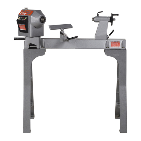
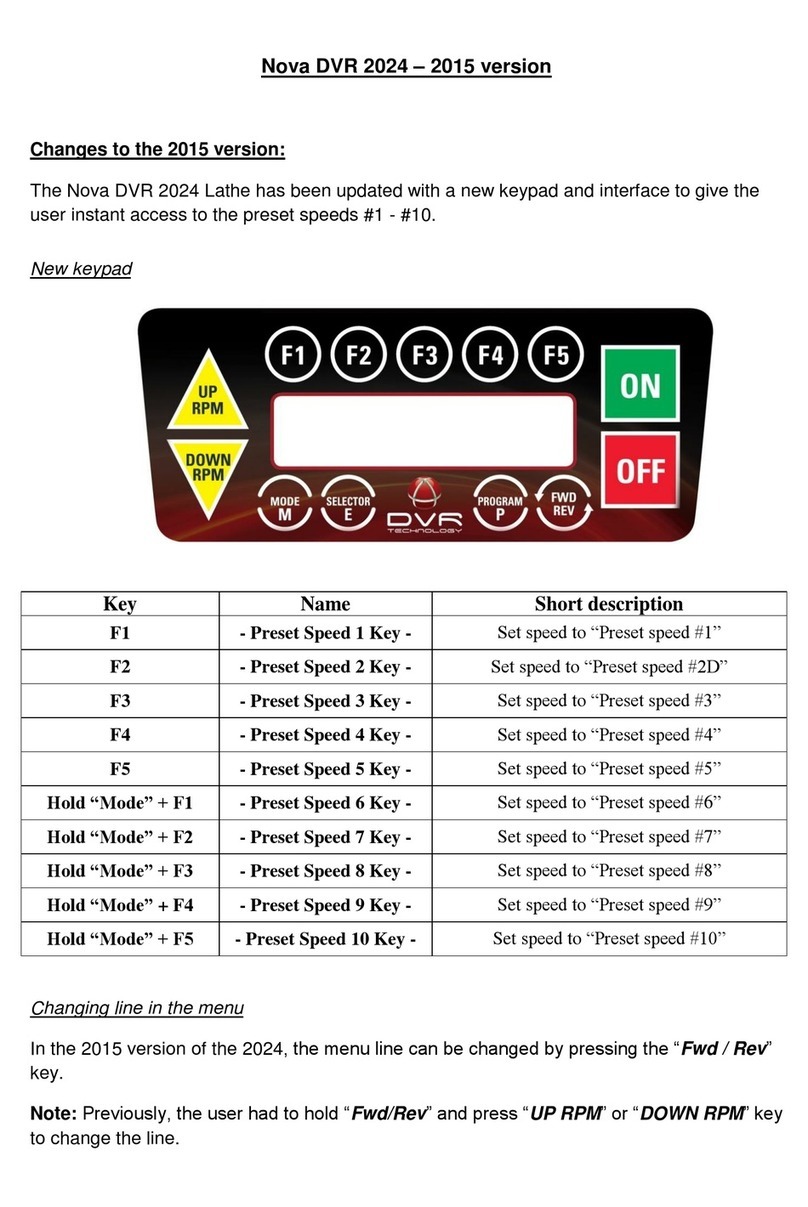
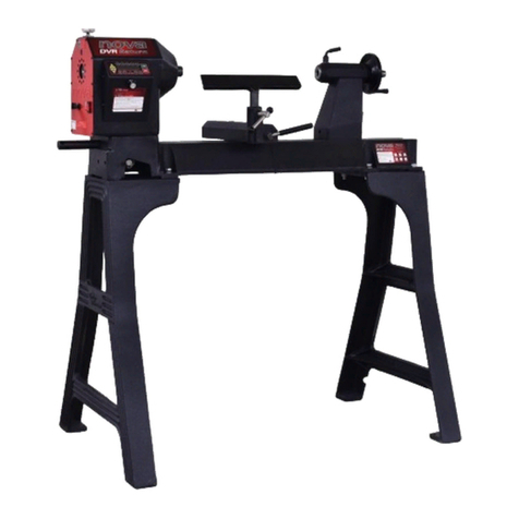
Teknatool nova ORION Series User manual

1
128-1019-004
OPERATION MANUA L
ORION 18” DVR LATHE™
Publication: 128-1019-004
Models:
55250 –USA
55251 –AUS/ NZ
55252 –EU
55253 –Canada
55254 –UK
Date: 10 October 2019

2
128-1019-004
Contact
Teknatool International Ltd
Phone: (+64) 9 477 5600
Teknatool USA
Phone: 727-954-3433
Customer Solutions
For all worldwide Inquiries, Repairs or Services (issues must be in writing)
Email: Service@Teknatool.com
Or you can contact the retailer where you purchased your NOVA Orion 18” DVR Lathe, for the contact details
please see our website www.teknatool.com

3
128-1019-004
Table of Contents
Contact.......................................................................................................................................................................................................2
Table of Contents.......................................................................................................................................................................................3
General Safety Rules..................................................................................................................................................................................4
NOVA ORION 18” DVR FEATURES..............................................................................................................................................................5
Lathe Specifications..............................................................................................................................................................................6
Package Contents.......................................................................................................................................................................................7
Assembling the Lathe.................................................................................................................................................................................8
Connecting Lathe Bed Sections ............................................................................................................................................................8
Attaching the Lathe Bed to Stand.........................................................................................................................................................8
Attaching the Headstock onto the Bed ................................................................................................................................................9
Locking the headstock into place .......................................................................................................................................................10
Attaching the Tool Rest onto the Bed ................................................................................................................................................11
Attaching the Tailstock onto the Bed .................................................................................................................................................11
NOVA ORION Bed Configuration ........................................................................................................................................................12
Connecting to Power ...............................................................................................................................................................................13
Ground Fault Interrupters (GFI)..........................................................................................................................................................14
Input Voltage Selection ......................................................................................................................................................................14
Setting Up Your Lathe ..............................................................................................................................................................................14
Workshop Environment .....................................................................................................................................................................14
Lathe Interface.........................................................................................................................................................................................15
Keypad Buttons ..................................................................................................................................................................................15
Lathe Home Screen ............................................................................................................................................................................15
Operating the Lathe.................................................................................................................................................................................16
Starting Operation..............................................................................................................................................................................16
Running the Lathe ..............................................................................................................................................................................16
Stopping the Lathe .............................................................................................................................................................................17
Adjusting the Speed............................................................................................................................................................................18
Accessing the Main Menu ..................................................................................................................................................................18
Favourite Speed Function...................................................................................................................................................................19
Using the lathe speed chart................................................................................................................................................................21
Changing the Home Screen Display Mode .........................................................................................................................................22
Switching between forward and reverse ...........................................................................................................................................23
Using the Lathe Spindle Lock..............................................................................................................................................................24
Swivelling the Headstock....................................................................................................................................................................25
Changing the <F> Key Functionalities.................................................................................................................................................26
Wireless Remote ................................................................................................................................................................................28
Password Lock ....................................................................................................................................................................................29
Lathe Settings .....................................................................................................................................................................................30
Maintaining Your Lathe............................................................................................................................................................................31
Maintenance after each use...............................................................................................................................................................31
Monthly maintenance ........................................................................................................................................................................31
6-months Maintenance ......................................................................................................................................................................31
Cleaning the Tool slide .......................................................................................................................................................................31
Cleaning the Tailstock.........................................................................................................................................................................31
Firmware Update .....................................................................................................................................................................................32
Checking the Firmware Version..........................................................................................................................................................32
USB Mode...........................................................................................................................................................................................32
Troubleshooting.......................................................................................................................................................................................33
Mechanical Issue ................................................................................................................................................................................33
Electrical Issue ....................................................................................................................................................................................34
Teknatool Warranty.................................................................................................................................................................................35
NOVA Orion Headstock Breakdown.........................................................................................................................................................36
NOVA Orion Lathe Parts List ....................................................................................................................................................................37
4
128-1019-004
General Safety Rules
WARNING
Failure to follow these rules may result in serious personal injury or death.
❖IMPORTANT: Before switching the lathe on, ALWAYS check the machine for the correct setting and speed
1. BEFORE OPERATING THE TOOL READ THE
MANUAL! Learn the machine’s application and
limitations, plus the specific hazards particular to it.
2. ALWAYS USE SAFETY GLASSES (must be ANSI
approved) Everyday eyeglasses usually are only impact
resistant and safety glasses only protect eyes. A full-face
shield will protect the eyes and face. Also use face or dust
mask if sanding operation is dusty.
3. WEAR PROPER APPAREL. Do not wear loose clothing,
gloves, neckties, rings, bracelets or other jewelry which
may get caught in moving parts. Nonslip footwear is
recommended. Wear protective hair covering to contain
long hair.
4. USE EAR PROTECTORS. Use ear muffs for extended
period of operation. Use muffs rated to 103 DBA LEQ (8
hour).
5. DO NOT USE IN DANGEROUS ENVIRONMENT. Don’t
use power tools in damp or wet locations or expose them
to rain. Keep work area well lighted. The NOVA ORION is
intended for indoor use only. Failure to do so may void
the warranty.
14. KEEP GUARDS IN PLACE and in working order.
15. USE CORRECT TOOLS. Do not use a tool or attachment to
do a job for which it was not designed.
16. USE RECOMMENDED NOVA ACCESSORIES. The use of
improper accessories may cause hazards.
17. DO NOT FORCE THE TOOL. It will do the job better and be
safer at the rate for which it was designed.
18. MAINTAIN TOOLS IN TOP CONDITION. Keep tools sharp
and clean for best and safest performance. Follow
instructions for lubricating and changing accessories.
19. NEVER STAND ON TOOL. Serious injury could occur if the
tool is tipped or if the cutting tool is accidentally contacted.
20. REMOVE ADJUSTING KEYS AND WRENCHES. Form a
habit of checking to see that keys and adjusting wrenches
are removed from tool before turning it on.
21. DO NOT OVERREACH. Keep proper footing and balance at
all times.
22. DIRECTION OF FEED.Mind the direction of
spindle/chuck/work to ensure a safe environment.
23. PAY ATTENTION TO WORK. Concentrate on your work. If
you become tired or frustrated, leave it for a while and rest.
24. SECURE WORK. Use clamps or a vice to hold work when
practical. Severe injury or death can occur if an object comes
free as it can become a dangerous projectile.
25. CHECK DAMAGED PARTS. Before further use of the tool,
any part that is damaged should be carefully checked to
ensure that it will operate properly and perform its intended
function. Check for alignment of moving parts, binding of
moving parts, mounting, and any other conditions that may
affect its operation. Any damaged part should be properly
repaired or replaced.
26. DRUGS, ALCOHOL, MEDICATION. Do not operate
machine while under the influence of drugs, alcohol, or any
medication.
27. DUST WARNING. The dust generated by certain woods
and wood products can be harmful to your health. Always
operate machinery in well-ventilated areas and provide
means for proper dust removal. Use wood dust collection
systems whenever possible.
28. DO NOT MODIFY OR USE THE LATHE FOR USES
OTHER THAN FOR WHICH IT WAS DESIGNED.
29. CALIFORNIA PROPOSITION 65 –SEE PAGE 39
6. KEEP WORK AREA CLEAN. Cluttered areas/benches
invite accidents. Build-up of sawdust is a fire hazard.
7. KEEP CHILDREN AND VISITORS AWAY. The NOVA
ORION is not recommended for children and ailing
persons. Such personnel and onlookers should be kept a
safe distance from work area.
8. MAKE WORKSHOP CHILDPROOF with locks, master
switches, or by removing starter keys.
9. GROUND ALL TOOLS. If the tool is equipped with a
three-prong plug, it should be plugged into a three-hole
electrical receptacle. If an adapter is used to
accommodate a two-prong receptacle, the adapter plug
must be attached to a known ground. Never remove the
third prong and add surge protection.
10. MAKE SURE TOOL IS DISCONNECTED FROM POWER
SOURCE whilst in service/maintenance mode.
11. DISCONNECT TOOLS FROM WALL SOCKET before
servicing and when changing accessories such as bits,
cutters, fuses, etc.
12. AVOID ACCIDENTAL STARTING. Make sure switch is in
the “Off” position before plugging in power cord.
13. NEVER LEAVE MACHINE RUNNING UNATTENDED.
Do not leave machine unless it is turned off and has come
to a complete stop.

5
128-1019-004
NOVA ORION 18” DVR FEATURES
Feature Name
Description
DIGITAL VARIABLE
RELUCTANCE (DVR)
ELECTRONIC DRIVE
The DVR motor uses smart motor technology to
provide an incredibly smooth and powerful drive.
The controller constantly monitors the spindle
position and maintains optimal spindle speed.
Additional power is added as it senses extra load
from the tool.
POWER TO TURN AND
BURN
1.75HP/110/ 2HP 220V Direct Drive DVR Motor.
ADD ON BED
EXTENSION SYSTEM
Each segment is 20"/510mmL
360°SWIVEL
HEADSTOCK
Lock at any position, plus detent locating positions
at 0°, 22.5°, 45° and 90°.
High accuracy and easy swivel
SOLID BED
STRUCTURE
CAD designed webbing to absorb
vibration throughout the bed length.
Exceptional structural strength.
8 FAVORITE SPEED
FUNCTION
Program your favorite speeds for faster and more
efficient project set ups
FLEXIBLE CAPACITY
TO MATCH YOUR
PROJECT
- 18"/457mm Capacity Over Bed
- 29"/736mm Capacity Outboard
(with optional outrigger accessory)
- 45.25”/ 1149.35mm Between Centers
SAFETY SENSING
FEATURE
It senses faults in the setup and advises of safety
issues- such as chisel dig in and spindle lock. It
then instantly shuts down power to the spindle.
ENERGY EFFICIENT
Intelligent (computer controlled) motor only draws
as much power as it needs for the application
INCREDIBLE
VARIABLE SPEED
RANGE
100 RPM - 5,000 RPM
WARRANTY
* 5 Year Warranty on Parts and Components
*2 Year Warranty on Motor and Electronics
* Restrictions apply

6
128-1019-004
Lathe Specifications
Metric
Imperial
Swing Over Bed
457.2mm
18”
Distance Between Centres
560mm / 1120mm
22” / 44”
Overall Size
1800mm (L) x 600mm (w) x 1240mm(H)
78.7” (L) x 26.6” (w) x 48.82” (H)
Weight
210 Kg
460 lb
Headstock
Spindle Thread
M33 x 3.5 RH*
1.25” x 8TPI
Headstock Spindle Taper
Morse Taper #2 (MT2)
Headstock Swivel
360° With detent positions at: -45°, 0°, 22.5°, 45°, 90°, 180°
Spindle Index
24 divisions (15 degrees apart)
Tailstock
Quill Taper
Morse Taper #2 (MT2)
Quill Travel
80mm
3”
Hole Through Tailstock
12.5mm
0.48”
Tool Rest
Length
300mm
12”
Shaft Diameter
25.4mm
1”
Motor Specifications
Motor Type
DVR Direct Drive Smart Motor
Motor Power Output
1.25KW (1.75HP)
Motor Speed Range
100 RPM ~ 5000 RPM
Input Voltage
110V ~ 240V
Input Frequency
50/60 Hz
Input Current
15A (max)
*M33 x 3.5 RH thread spindle only available in European model. All other market models will have the 1.25inch x 8 TPI spindle.

7
128-1019-004
Package Contents
ITEM NUMBERS
DESCRIPTION
SKU
1
Headstock Assembly (+HMI)
5699001 + 5699005
2
Tool Slide Assembly
5699004
3
Tailstock Assembly
5699033
4
Main Bed
5699021
5
Bed Extension*
5699035
6
Lathe stand
5699018
7
12”(300mm) Tool Rest
5699024
8
Knockout/Operating Bar
5699033
9
2MT Spur Centre
2MTSPUR
10
2MT Live Centre
5020
11
6” (150mm) Face Plate
FP150L
Note: Only US model includes the second bed extension. All other market models will include one bed extension unit.

8
128-1019-004
Assembling the Lathe
Connecting Lathe Bed Sections
Place the lathe bed onto a leveled surface with a 24mm thick block of wood or anything similar.
Connect the main bed and extension bed section together but using the bolts
Make sure to use the washers included in the package to prevent damage to the lathe bed sections.
Attaching the Lathe Bed to Stand
SAFETY CAUTION: Each of the lathe stand legs have a significant
mass (Approximately 35Kg) therefore 2~3 people will be needed for assembly.
Place one of the lathes’ stand
leg on top of the lathe bed
turned upside down.
Use 4 bolts to secure the
stand leg onto the lathe bed.
Place 24mm thick wooden blocks
under each bed section so the bed
sections are levelled
ASSEMBLY NOTE
Washer
Spring
Washer
Bolt
Repeat for all 4 bolt holes on bed
ASSEMBLY NOTE
Fasten all the bolts tight enough so it barely touches
the stand legs but do not fully tighten until the stand
leg has been positioned appropriately.

9
128-1019-004
Attaching the Headstock onto the Bed
SAFETY CAUTION: The headstock unit itself has a significant mass
(Approximately 50Kg) therefore extreme caution must be taken to lift the headstock up to a
height where it can be attached to the bed.
Insert the centre pin of the headstock into the bore of the lathe bed to mount the headstock.
Align the lathe bed mounting holes
with the slots on the stand legs
before inserting the bolts.
Make sure the bed side edge
matches the machined surface
edge of the stand
The direction of the set screw on
the headstock centre pin must
match the slot on the lathe bed
bore where it gets inserted.

10
128-1019-004
Secure the headstock onto the lathe bed by using the 8mm flat wide
washer and M8 hex head bolt included in the packaging.
Insert the bolt and washer from underneath the stand through the
hole and thread the bolt onto the headstock centre pin.
➢Note: A hex socket extension may be needed to tighten this bolt.
Locking the headstock into place
The headstock is locked into place by the headstock locking pin.
1.
2.
Insert the hedstock lock pin into the bore on the lathe bed as
shown in the above image.
Hand tighten until it becomes firm
Further tighten the headstock lock pin by using the
operating bar until firm to ensure the headsock is
locked in place.
WARNING!
Do not over tighten as it may cause damage to the
lathe bed.

11
128-1019-004
Attaching the Tool Rest onto the Bed
Attaching the tool rest onto the tool slide
Slide the tool rest assembly onto the bed by matching the tool slide lock plate
with the cut out made on the side of the lathe bed sections.
➢Note: Turn the handle to adjust the position of the tool
slide lock plate if it cannot slide onto the lathe bed section.
Loosen the tool rest lock handle and
ensure nothing is inside the tool slide
bore.
Insert the tool rest into the tool slide
bore and tighten the tool rest lock
handle to secure its position.
Attaching the Tailstock onto the Bed
Slide the tailstock assembly onto the lathe bed section by matching the
tailstock lock plate with the cut out made of the side of the lathe bed
sections.
➢Note: Turn the tailstock lock handle to adjust the
position of the tailstock lock plate if the tailstock
cannot slide onto the lathe bed section.
Attach any known straight sharp pointed tool (E.g. Spur and live centres) on the headstock spindle and tailstock quill to check for
axial alignment between headstock and tailstock.
Vertical Alignment
Horizontal Alignment
Make sure both points are touching each other in both directons

12
128-1019-004
NOVA ORION Bed Configuration
Multiple configurations to suit unique size needs
Basic Configuration
❖
Center to Center Distance
Metric
Imperial
558.8mm
22”
Basic Configuration with Bed Extension
Center to Center Distance
Metric
Imperial
1117.6mm
44”
3-Bed Configuration
Center to Center Distance
Metric
Imperial
1117.6mm
44”
EU/World Standard
Bed Accessory Extension (5699035)
Available for additional purchase
U.S. Standard
3-Beds

13
128-1019-004
Connecting to Power
Warning!
Improper power connection may result in a risk of electrical hazard.
Before plugging the NOVA Orion lathe into the power source:
1. The main power switch is turned off
2. Power source is switched off
Socket type power cable
Hardwired power cable
Note: This image on the left-hand side is the European version of the NOVA Orion wood lathe. Other versions will have
a hard-wired power cable (shown on the image on the right-hand side)
The power cord that is installed on the NOVA Orion lathe will have a three-prong plug which includes a ground
prong. The plug must be connected to a matching outlet that his properly installed and grounded in accordance
with local electrical codes.
For 115V Outlet Only:
A temporary adapter can be used to plug into a two-pole outlet if a three-prong outlet is unavailable in your
environment. The ground tab on the adapter must be connected to the screw on the outlet for proper grounding.
This adaptor should only be used until a qualified electrician can install a properly grounded outlet.
➢Note: If an extension cable is required, make sure to check the following:
1. Extension cable gauge
2. Is the cable properly insulated?
If in any doubt, please contact your local electrician to inspect the cord according to the local electrical standards
before using it.
❖IMPORTANT:
•A surge protection device must be used when using the lathe.
•A surge protection device must be rated to at least 15A should be used in countries where 115V are used
as a standard. In countries where 240V is used, a surge protector must be rated to either 10A or 15A.
•A surge protector with Joules rating of 3900J will be suitable for DVR motors.
Make sure the “O” side of the
rocker switch is pressed in before
connecting the power cable to the
power source.

14
128-1019-004
Ground Fault Interrupters (GFI)
For a GFI to be compatible with the DVR motor, it must have a leak current threshold rating of 30mA
(0.03A)
➢Note: Normal household GFI will typically be rated at 5mA (0.005A) which
may trigger during the operation of the DVR motor. However, frequent
tripping of the GFI will not cause any harm to the DVR motor or its control
electronics as it has a built-in protective circuit to prevent damage from
frequent switching.
Input Voltage Selection
The NOVA Orion lathe is capable of handling both 115V and 240V without any changes to its internal circuits.
The lathe will automatically recognize the input voltage to the lathe and adjust the output power. Simply
change the input power plug to a suitable plug for the desired input voltage to change the lathe’s input voltage.
i.e. For US:
For 115V
For 240V (NEMA 6-15P)
For regions where 240V is standard:
Europe
Australia/ New Zealand
Setting Up Your Lathe
Workshop Environment
Your workshop should set up appropriately for you to effectively use the lathe. The workshop should be setup
with the following factors taken into consideration:
1. Lathe location
Locate the NOVA Orion lathe close to a power source in an area with good amount of lighting. Leave enough
clearance whenthe lathe headstock is swivelled around.Other machines in the workshop should not interfere
with the movement/operation of the lathe.
2. Lighting
The work shop should have adequate lighting. There should be enough lighting around the lathe not to cast
shadows upon the workpiece. If possible, locate the lathe near a window. A portable spotlight might be
helpful.

15
128-1019-004
3. Electrical
The NOVA Orion lathe requires an appropriate power outlet nearby to power the motor. The outlet wiring
must meet the local electrical safety standards. If in any doubt, seek advice from an electrician. The length
of an extension cable should be reduced as must as possible.
4. Ventilation
Workshop must have an adequate level of ventilation. The level of required ventilation depends on the size
of the workshop and the amount of work that is done within the workshop. The use of dust collectors and
filters will minimize your health risk.
Lathe Interface
Keypad Buttons
Lathe Home Screen
There are 2 home screen display modes available for the NOVA Orion lathe
LARGE NUMBER DISPLAY
NORMAL NUMER DISPLAY
The large number display will display:
▪Set RPM of the lathe (When the motor is not turned
on). This will change to the actual RPM of the lathe
spindle when the motor is turned on.
The normal number display will display:
▪Favourite speed assigned to each of the <F> keys.
▪From the right, the favourite speeds are assigned to:
<F1>, <F2>, <F3>, <F4>

16
128-1019-004
▪Forward and reverse state
▪Current state of the lathe
▪The second set of favourite speeds will not be
displayed.
▪When the motor is off, set RPM of the lathe. This will
change to the actual RPM of the lathe spindle when
the motor is turned on.
▪Forward and reverse state
▪Current state of the lathe
Operating the Lathe
Starting Operation
When the main power switch has been turned ON, the LCD screen on the HMI will display the texts shown below:
Additionally, the following screen with be shown at the end of the starting sequence if the braking function is enabled on
the lathe. This message can be cleared to proceed on the lathe home screen by pressing any key on the HMI. The home
screen will be shown once the starting sequence is completed.
Running the Lathe
Press the <ON> key while on the home screen to
start the motor.
The motor will accelerate to its set speed and keep
its set speed.

17
128-1019-004
Stopping the Lathe
Press the <OFF> key while on the home screen to
stop the motor.
The motor 2 types of behaviours when the
<OFF> key is pressed:
•Motor stops and no brakes applied
•Motor stops and brakes are applied
Emergency Stop Switch
The emergency stop switch can be pressed to
stop the motor any time during operation.
Brakes will be applied when the emergency
stop switch is pressed.
Once the emergency stop switch is pressed,
the motor will not start until the switch is
released by twisting it in the clockwise direction.

18
128-1019-004
Adjusting the Speed
Set speed of the lathe motor can be adjusted anytime while
the HMI is on the home screen.
The set speed can be adjusted by turning the speed
adjustment knob.
Input Set Speed Function
The input set speed function allows to quickly set the lathe
to any speed within 5rpm by using the function <F#> keys
Accessing the Main Menu
The main menu is used to access all available software features on the lathe.
Press <Menu> key while on the home screen to access
the main menu of the lathe.
The screen will switch to 0the main menu once the key
is pressed. =]\]=[]=[p-]=[p--
Main Menu Contents
The following are the contents of the main menu in the NOVA Orion lathe:
1. Speed Chart
2. Input Set Speed
3. Edit Fav Speed #1-8
4. Profile: <Selected profile>

19
128-1019-004
5. Customize F Keys
6. Lathe Settings
7. Wireless remote
8. Motor Parameters
9. Password Lock
10. Firmware Upgrade
11. Version Info
Each function in the menu will be described in detail in the later section of this manual.
Favourite Speed Function
Favourite speed function allocates pre-set speed to each of the function keys (<F> keys) so the most commonly used lathe
speeds can be accessed without using speed dial knob.
A total of 2 speeds can be set to a single <F> key (i.e. A total of 8 speeds can be set to the favourite speed function).
Setting Favourite Speed Function
➢Note:The <F> keys must be set to use the favourite speed function to
have access to all assigned speeds. Refer to page27 to check the
alternative functions that can be assigned to the <F> keys.
While on the home screen, press one of the <F> keys where
the desired speed is assigned to.
Press the <F> key once to access the first assigned speed
Press the <F> key again to switch between the first assigned
speed and the second assigned speed.
The default speeds for the favourite speed function are the
following:
Allocated
Keys
Favourite speed
Number
Default Allocated
Speed
F1
#1
250
#2D (Default)
500
F2
#3
750
#4
1020
F3
#5
1250
#6
1500
F4
#7
1750
#8
2000

20
128-1019-004
After pressing one of the <F> key to change the lathe speed,
the lathe screen will change a screen where it asks for
conformation to change the lathe set speed.
Press<F/R> key to confirm and change the lathe to the speed
allocated to the favourite speed.
Press <Menu> key to cancel setting the speed from favourite
speed and return to the home screen.
Editing the Favourite Speed Function
Press the <Menu> key while on the lathe home screen
to access the main menu of the lathe.
Navigate down the “Edit Fav Speed #1”item on the
menu.
Press in the speed control knob to enter the
function.
Use the speed control knob to navigate down to the
favourite speed to edit.
➢Note: There are 2 pages to this screen. The pages
will automatically switch when scrolled down.
Press the speed control knob when the cursor is next
to the favourite speed to edit.
This manual suits for next models
5
Table of contents
Other Teknatool Lathe manuals

Teknatool
Teknatool NOVA 3000 User manual

Teknatool
Teknatool NOVA Comet II Technical reference manual

Teknatool
Teknatool Nova Mercury User manual

Teknatool
Teknatool NOVA DVR XP User manual

Teknatool
Teknatool NOVA DVR SATURN User manual

Teknatool
Teknatool NOVA TL1200 User manual

Teknatool
Teknatool Nova DVR 2024 User manual

Teknatool
Teknatool nova Neptune DVR User manual

Teknatool
Teknatool NOVA 1624 II User manual