Haas TL-1 User manual

Toolroom Lathe
Operator’s Addendum
© 2010 Haas Automation, Inc.
96-0112 Rev W
July 2010


1
96-0112 Rev W
July 2010
Table of Contents
1. Warranty ...........................................................................................2
2. Safety ................................................................................................2
3. InStallatIon.........................................................................................3
ShIppIng Bracket removal.................................................................3
levelIng ............................................................................................3
tl-4 levelIng....................................................................................4
electrIcIty requIrementS ..................................................................5
4. operatIon ...........................................................................................7
poWer up .................................................................................................7
optIonal taIlStock (Standard WIth tl-4) operatIon ...............................8
optIonal tool turret removal/reInStallatIon ........................................9
tt-4 (tl-1/2) ...................................................................................9
tt-20 (tl-3) .....................................................................................11
tt-10 (tl-4) .....................................................................................12
manual mode...........................................................................................15
machIne poSItIon ...............................................................................15
tool offSetS ...........................................................................................16
automatIc mode .......................................................................................16
IpS recorder ..........................................................................................18
alarmS/meSSageS dISplay .................................................................19
5. maIntenance........................................................................................20
luBrIcatIon - toolroom lathe ..........................................................20
chIp fIlter ........................................................................................21

296-0112 Rev W
July 2010
1. WARRANTY
All new Haas Toolroom Lathes are warranted exclusively by the Haas Automa-
tion’s (“Manufacturer”) limited warranty against defects in material and work-
manship for a period of 1 year from the date of purchase, which is the date that
a machine is installed at the end user. See the Warranty section of the Lathe
Operator’s Manual for further warranty information.
2. SAFETY
Read and Follow all Safety Warnings – Familiarize yourself with the Safety
section of the Operator’s Manual. Be aware of the other people around you in
the shop; ying chips can seriously injure people who may not be a safe dis-
tance away. Always wear safety glasses. Initial cuts/setups should be cut at a
slower speed to reduce the possibility of tool or machine damage. As with any
open frame lathe, chip screens are highly recommended.
The Toolroom Lathe (with the exception of the TL-4) is equipped with a hand
held safety switch. The button must be pressed any time automatic machining
is taking place. Releasing the switch will cause the spindle and axes motion to
stop. In order to resume automatic machining, the button and Cycle Start must
be pressed (it is not necessary to hold down the Cycle Start switch).
Workholding Safety
The care and safety issues of the workholder’s manufacturer must be followed
to ensure a safe working environment and to avoid damaging the machine.
Cleaning and maintenance should be done often. Inspect the equipment for
improper wear, cracks or missing pieces. Do not operate if any of these are
found.
Do not start the lathe until it is set up properly. Interference between the work-
holding equipment and the lathe will cause damage to both.
Use the correct chuck size; do not allow the chuck jaws to protrude past the
chuck body.
Use additional support if turning long parts.
Remove the chuck wrench before starting the machine.
Do not modify workholding equipment.
Never exceed the maximum speed of the chuck.
Additional safety issues are outlined in the Lathe Operator’s man-
ual.

3
96-0112 Rev W
July 2010
3. INSTALLATION
Shipping Bracket removal
TL-1/2/3
1. Remove the one (1) hex head bolt that mounts the shipping bracket to the
spindle head, and the two (2) bolts that mount the shipping bracket to the table.
2. After removing shipping bracket, replace two bolts removed from table with
button head screws supplied.
3. Remove the pendant shipping bracket. There are 4 screws securing the
pendant to the arm.
TL-4
1. Remove six red shipping brackets; three from the base of the tailstock, one
from the pendant, one from the traveling door and one from the table to the
spindle.
TL-1/2 Shipping Bracket
leveling
1. Position the cross-slide close to the chuck (this is how the machine was
shipped), and place a machinist’s level on the cross-slide, parallel to the X-axis.
TL-1 Shown

496-0112 Rev W
July 2010
2. Run Z-axis left to right and level machine by adjusting leveling screws. Verify
each leveling screw requires approximately same torque to turn for proper load-
ing. Once completed, tighten lock nuts on leveling screws.
3. Re-position cross-slide close to chuck, and place the level on the cross-slide,
parallel to the Z-axis and run Z-axis left to right and level machine by adjusting
leveling screws. Verify each leveling screw requires approximately same torque
to turn to ensure proper loading. Once completed, tighten lock nuts on leveling
screws.
tl-4 leveling
Place the lathe in position on the shop oor. Rough level by measuring from the
oor to the bottom of the base (very close to 3.5 inches). Do this to the 4 corner
leveling screws. The 4 middle leveling screws must not touch the leveling pads.
Loosely screw the jam nuts onto the leveling screws. An electronic level is
required for the installation. The leveling specication is +/- .00015”.
1. Loosen the front corner leveling screw (3) so that it is just above the leveling
pad and jog the cross-slide to the end of Z-axis travel closest to the spindle head
and to the middle of X-axis travel.
2. Position the level on the cross-slide, parallel to the X-axis and adjust the cor-
ner leveling screws closest to the spindle head (1,4) until machine is level.
3. Position the level parallel to the Z-axis. Adjust the corner rear leveling screw
closest to the tailstock (2) until machine is level. The front screw (3) was left
loose and must remain loose.
4. Position the level parallel to the X-axis. Jog the cross slide along the Z-axis
from the spindle head to the tailstock. Adjust the front corner leveling screw (3)
until machine is level.
5. Jog Z-axis through its travel range to verify there is no twist. Adjust corner
leveling screws until twist is removed.
6. Recheck the level in both X and Z-axes with the level parallel to the X-axis
and recheck the level in both X and Z-axes with the level parallel to the Z-axis.
7. Finish leveling procedure by adjusting the 4 leveling screws in the center of
the lathe until they are touching the leveling pads. Secure all leveling screws
with a jam nut. Verify lathe remains level (X and Z-axes).

5
96-0112 Rev W
July 2010
electricity requirementS
Important! Refer to local code requirements before wiring ma-
chines.
All machines require:
The power source must be grounded
Frequency range is 47-66 Hz
Line voltage that does not uctuate more than +/-5%
Harmonic distortion is not to exceed 10% of the total RMS voltage
Voltage Requirements
Input Voltage Low Volt. TL-1,2 - 208V 3PH / 240V 1PH ±10%
TL-3, TL-3B, TL-3HT, TL-3W, TL-4 - 240V
3PH
High Volt. 354-488V 3PH
Power Supply Breaker (Low Volt) TL-1,2 20 AMP 3PH / 40 AMP 1PH
TL-3 50A, TL-3B, TL-3HT 100A, TL-4 200A
Haas Circuit Breaker (Low Volt) TL-1,2 40A, TL-3 40A, TL-3B, TL-3HT 80A,
TL-4 200A
Power Supply Breaker (High Volt) TL-1,2 20A
TL-3 25A, TL-3B, TL-3HT & TL-3W 50A
Haas Circuit Breaker (High Volt) TL-1,2 20A, TL-3 20A, TL-3B, TL-3HT 40A
If service run from elec. panel
is less than 100’ use: TL-1,2 1PH - 8 GA Wire /
3PH - 10 GA Wire
TL-3 8GA Wire (High 12
GA.),
TL-3B, TL-3HT 4GA. Wire
(High 8GA), TL-4 0GA
If service run from elec. panel
is more than 100’ use: TL-1,2 1PH - 6 GA Wire /
3PH - 8 GA WIRE
TL-3 6GA. Wire (High 10 GA.), TL-3B,
TL-3HT 2GA. Wire (High 6GA.), TL-4 0GA
Warning!
A separate earth ground wire of the same conductor size as the input
power is required to be connected to the chassis of the machine.
This ground wire is required for operator safety and for proper opera-
tion. This ground must be supplied from the main plant ground at
the service entrance, and should be routed in the same conduit as
the input power to the machine. A local cold water pipe, or ground
rod adjacent to the machine cannot be used as a primary ground.
The maximum voltage leg-to-leg or leg-to-ground should not exceed 260 volts.
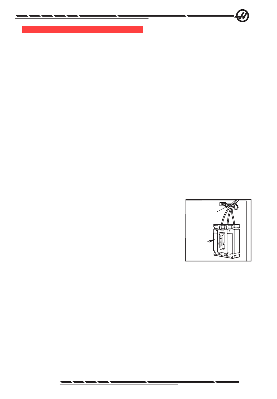
Main
Circuit
Breaker
Ground
Line L1 L2 L3

696-0112 Rev W
July 2010
Connecting the Toolroom Lathe to Power
1. Ensure the main circuit breaker is in the OFF position. Connect the power
lines to the top terminals of the main circuit breaker. Connect the separate
ground line to the ground bus to the left of the circuit breaker.
NOTE: For Single Phase operation, only circuit breaker terminals L1
and L3 are used.
2. T5 is the small transformer mounted on the power supply assembly next to
the main circuit breaker. Two input connectors allow it to be connected to either
240V or 200V. If incoming power is 220-250 VRMS, use the 240V connection.
If incoming power is 187-219 VRMS, use the 200V connection. Failure to use
the correct input connector results in either overheating of main contactor or
failure to reliably engage the main contactor.
3. The main power transformer is located at the bottom-right corner of the
control cabinet. It also has two different input connections located at terminal
board TB2. If incoming power is 187-215 VRMS, connect wire 74 to the 208V
position (center). If incoming power is 216-250 VRMS, connect wire 74 to the
240V position (left).
4. Turn main circuit breaker ON and press control panel Power-On button.
Verify 320V Power Supply fault indicator displays “1” (normal power-up se-
quence). Verify DC bus voltage on pins 6 & 7 is approximately 335VDC if
powered from 240V, or closer to 290V if powered from 208V. If voltage is not at
least 260VDC, call Service Department.
5. Turn the main circuit breaker Off, close the door, lock the latches and turn
the power back on.

7
96-0112 Rev W
July 2010
4. OPERATION
The Toolroom Lathe includes features aimed at a machinist used to a manually
positioned lathe. The lathe uses familiar manual handles, while giving full CNC
capabilities. Haas Automation has added software features to the machine
control, to help develop full CNC programs and ease operation of manual
mode.
At power up, the Toolroom Lathe screen is displayed. This screen shows the
X and Z position of the lathe as well as the spindle speed. To navigate through
the menus, use the left and right arrow keys. To select the menu, press Write/
Enter. Some menus have sub-menus, which again use the left and right arrow
keys and Enter to select a sub-menu. Use the arrow keys to navigate through
the variables. Key in a variable using the number pad and press Write/Enter. To
exit the menu press Cancel.
+Z
-Z
+X
-X
ROTATINGPARTSINSIDE,
KEEPHANDSAWAY.
Turret
Lathes
Table
Lathes
-X
+X
+Z
-Z
+X
-X
+Z
-Z
To change to full CNC mode, press any Display key except Offset. Press
Handle Jog to return to Toolroom Lathe menus. A program entered through
Toolroom Lathe screens is accessible in MDI mode (full CNC). A G-Code list
is described in the Operator’s manual and includes examples to demonstrate
G-code usage.
power up
The lathe is powered up by pressing the “Power On” button. If necessary,
manually jog cross-slide and saddle away from workpiece. If equipped with tail-
stock, unclamp it, move it to farthest position from chuck and retract quill. Press
“Power Up/Restart” and the cross-slide will automatically nd home in the X
axis, while the saddle nds home in the Z axis.
NOTE: Manually jog the X-axis toward the operator and the Z-axis away
from the spindle, before pressing Power Up/Restart. This will
save time when the machine automatically nds home. When
equipped with a tool turret and a tailstock, be sure to zero
return single axis so that large tools do not get obstructed by
the tailstock.

896-0112 Rev W
July 2010
optional tailStock (Standard with tl-4) operation
Loosen the clamp at the base of the tailstock casting. The tailstock base is
positioned manually, then secured in place using the two clamps. The hand
wheel on the rear of the casting is then used to drive the quill in and out. The
TL-1/2 tailstock has a #4 Morse taper (MT4), the TL-3’s use an MT5 and the
TL-4 uses an MT6.
The TL-4 tailstock is moved by pinning it to the saddle and using the hand-
wheel on the pendant to jog the Z-axis and move the tailstock into the desired
position. To secure the TL-4 tailstock:
1. Tighten the pressure knob on the hydraulic system.
2. Use the hand pump on the hydraulic system to increase the pressure to
between 2000 and 2300 psi.
3. Use the tailstock handwheel to extend the quill and lock it into place with the
lever.
NOTE: Remember to remove pressure by loosening the hydraulic
pressure knob before moving the tailstock.
CAUTION: When hydraulic pressure drops to 1500 psi during operation,
the spindle will stop. Check hydraulic pressure often to ensure
it does not drop below 2000 psi.
When tailstock is not in use, jog it to the rear stops. Hydraulic pressure is not
needed to keep it in position.
optional tool turret removal/reinStallation
If installed, the optional tool turret can be removed if extra space is required for
large parts or special tooling setups. The following instructions detail removal
and reinstallation for each of the tool turrets available.
tt-4 (tl-1/2)
Removal
1. Turn the air to the tool changer off (Either disconnect air to the regulator or
turn the regulator knob counterclockwise until pressure reads zero). Remove
the turret motor cover and disconnect the air line and electrical cables from
the turret. Unbolt the turret and lift off of the machine (Note shim locations for
reinstallation).
2. Remove the riser block from the cross slide (TL-2).
3. Cap the electrical cable and air line, then install the chip shield.
4. Change setting 113 to either “TL Post” or “Gang TL” as appropriate.

9
96-0112 Rev W
July 2010
Reinstallation
1. Clean the cross slide surface and set the TT-4 on the cross slide. TL-2:
Install riser block between tool changer and cross slide.
2. Install shims and bolt tool changer to cross slide (4 bolts), but leave loose.
3. Connect control cables and air line. Install the motor cover.
Realignment
1. Put a magnetic base indicator on the spindle casting.
2. Place the tip of the indicator on the bottom inside surface of the tool turret in
the X direction.
3. Jog the X-axis and check the alignment of the tool changer along the entire
surface indicated.
4. Alignment error should not exceed 0.002” (0.051 mm) over 5.5” (140 mm)
travel.
Steps 1-4 Steps 5-7
5. Place the tip of the indicator on the bottom inside surface of the tool turret in
the Z direction.
6. Jog the Z-axis and check the alignment of the tool turret along the entire
surface indicated.
7. Alignment error should not exceed 0.002” (0.051 mm) over 5.5” (140 mm)
travel.

10 96-0112 Rev W
July 2010
8. To correct level alignment errors, surface grind or mill the shims to the ap-
propriate thickness. The two surfaces must be parallel within .002” (0.051 mm).
9. Re-install the shims in their appropriate locations. If the tool center is below
spindle center after grinding, shim stock may be placed between the shim and
tool changer housing to restore the height.
Shim Locations Steps 10-13
10. Place the indicator tip against the inner vertical surface of the tool turret
(indicated by the shaded area on the illustration).
11. Jog the X-Axis and measure the alignment of the tool turret over the entire
surface.
12. Alignment error should not exceed 0.001” (0.025 mm) over 5.5” (140 mm)
travel.
13. Tap the base to correct any misalignment and tighten the turret mounting
bolts to 130 ft-lbs (176 Nm).
14. Re-verify alignment.
15. Change Setting 113 to “Auto”.
tt-20 (tl-3)
Removal
1. Turn off air to the turret at the regulator, then disconnect the air line and elec-
trical cable from the turret.
2. Remove the turret mounting bolts.
3. Install eyebolts into the threaded holes on both sides of the turret and use a
suitable lifting device and straps to lift the turret off of the riser block. Be sure
to lift the turret high enough to clear the dowel pins in the riser block before
moving it out. Note the number of shims used at each corner of the turret for
reinstallation.
4. Remove the riser block.
5. Change Setting 113 to either “TL Post” or “Gang TL” as appropriate.

11
96-0112 Rev W
July 2010
Reinstallation / Alignment
1. Stone and clean the riser block. Clean the cross slide.Align the riser block
(20-3525A) with the edge of the cross slide on the tailstock side and secure
loosely with ve bolts. Snug one corner bolt to allow it to act as a pivot during
alignment. The riser block will overlap the front of the cross slide table by a
small amount.
Riser Block Alignment Turret Alignment
2. Make sure the dowel holes on both the riser block and the turret are clean.
Insert two brass dowel pins into the riser. Line up the pins with the holes on the
bottom of the turret and install, being careful not to damage anything. Bolt the
turret to the riser block and snug the bolts.
3. Place an indicator tip against the face of the turret. Jog the X-Axis and check
for parallelism between the spindle casting and turret face. Tap the riser block
to correct any misalignment, within .001”. Temporarily connect air (set to 80 psi)
and power. Rotate the turret 90 degrees and recheck turret face atness, within
.001”. When alignment is conrmed, tighten the accessible riser block bolts
with the turret still installed, then lift the turret and tighten all riser block bolts to
90 ft-lbs. Reinstall the turret (with the original shims in place, if available) and
reverify alignment before proceeding. Disconnect air and power.
4. Check turret height by setting up boring bar holders and appropriate diam-
eter bars in positions 1 (toward machine front) and 4 (toward machine rear)
of the turret. The bars should extend 2” from the holders. Place the tip of the
indicator on top of the bar in position 1 and jog the Z-axis along the bar. The
deviation can be no more than .001” over the 2” travel. Move the X-axis until
the bar is in line (centered) with the spindle. Measure the height difference
between the bar and spindle. The two surfaces must be parallel within .001”.
Rotate position 4 to the front and repeat measurements. Use .001” horseshoe
shims to raise the turret as necessary to align. Trim the tabs from the shims
ush with the spacer/turret assembly. When alignment is complete, tighten the
turret bolts to 90 ft-lbs.
5. Change Setting 113 to “Auto”.

12 96-0112 Rev W
July 2010
tt-10 (tl-4)
Removal
1. Turn off the machine. Turn off and disconnect shop air. Remove the T outlet
from the air regulator and reinstall the elbow tting. Reconnect lube system air
line to this outlet.
2. Remove the TT-10 rear cover.
3. Disconnect all cables, coolant and the air line from the turret. Detatch the
turret cable carrier from its bracket.
4. The cables and cable carrier can be stored as a unit on the back side of the
rear chip shield. See the following illustration. Replace the cutout cover and
secure with the screws used for the cable carrier.
5. Remove the mounting bolts. Install eyebolts and use a suitable lifting device
to remove the turret from the lathe.
6. Restore any previous coolant connection before proceeding.
Reinstallation
1. Clean the cross slide surface. Install eyebolts and use a suitable lifting
device to mount the TT-10 unit to the cross slide plate using four .75-10 x 2.75”
hex head bolts (retrots on machines built before June 2008 will require .625”
shoulder bolts). The bolts should be snug, but not fully torqued at this point.
2. Remove the rear cover of the TT-10. Secure the cable carrier bracket to the
inside of the turret casting using two .25-20 x .5” BHCS.
3. Install the cable carrier between the TT-10 and the rear chip shield cutout.
Secure with four .25-20 x .5” BHCS at each end (the screws at the chip shield
end secure the cable carrier and the tray to the chip shield). Wrap the cables
where they exit into the turret. Pull any excess cable back and wrap them in
individual loops in the control cabinet. Close the Z-axis cable carrier.

13
96-0112 Rev W
July 2010
4. Connect the air line to the air in port on the solenoid. Connect the motor and
encoder cables.
5. Switches are labeled on the gearbox cover. Connect the TT status (clamp /
unclamp) cable and solenoid cable through the connector panel. Connect the
home switch to the home switch cable off of the motor encoder cable.
6. Connect the coolant line to the turret, using a reducer tting at the cross
slide ball valve.
7. Reconnect shop air and set the machine regulator to 85 PSI.
8. Power on the machine.
9. Run the machine to maximum travel in the Z and X axes and check cable
travel.
Alignment
Squaring the TT-10 to the base:
1. Place mag base / indicator on the Z-axis rail on the operator side. Touch the
face of the turret at tool position 1 and jog the X axis. Squareness error should
not exceed 0.0004” over 10” of X-axis travel.
2. Tap the TT-10 into position to correct any error.
To spindle centerline:
1. Attach T-0028 (SL-40 BOT inspection tool holder) to tool position 1.
2. Install 15-2534 (spindle adapter plate) and a spindle alignment bar (T-1312
or T-1652).
3. Mount the indicator to the spindle alignment bar. Manually rotate the spindle
to sweep the inside diameter of the inspection tool and measure runout. It
should not exceed 0.001” for this tool position.
4. Repeat steps 1-3 with the inspection tool at position 4. TIR should not ex-
ceed 0.003” at this position.

14 96-0112 Rev W
July 2010
5. Surface grind or mill shims to correct runout, as close to 0.0000” as possible
at tool #1.
6. When runout is eliminated, repeat the base squaring procedure above.
Torque the mounting bolts to 200 ft-lbs.
manual mode
Select Manual Mode by moving highlighted tab to “Manual Mode” and press
Write/Enter.
X and Z Axes
This mode positions the cutting tool using the hand wheels or the pendant jog
handle. When the lathe is initially powered up, the handwheels position the
cutting tools and “XZ MAN” is displayed at the bottom of the pendant screen.
To change position control to pendant jog handle, press Shift key and X+ or
X- to control X-axis or Shift key and Z+ or Z- to control Z-axis. To return to hand
wheel control, press the Shift key and X+, X-, Z+ or Z- again. Note that the
sequence of using “Shift” and selecting an axis will work on most screens.
Spindle
Spindle is commanded by entering value for the spindle speed and pressing
either FWD or REV. The spindle speed override keys ( +/- 10%) can be used to
adjust commanded speed. This also works on most screens.
machine poSition
Machine coordinates are shown on right side of display screen. Four coordi-
nate modes are accessed by pressing the POSIT button, and can be scrolled
through using Page Up and Page Down. These are:
POS-OPER – This is for the operator/setup person to use as desired, and is
not used by the control for any positioning functions. In JOG mode, and with
this display selected, select an axis (press X- or X+ for the X-axis or Z- or Z+
for the Z-axis). Press the ORIGIN button to set the display to zero. The (OPER-
ATOR) display will then show position relative to this newly reset zero position.
POS-WORK – Shows how far the tool is away from the X and Zzero of the
programmed part. On power up, it displays the value in work offset G54 auto-
matically. The machine uses this coordinate system to run the part.
POS-MACH – Machine coordinate system automatically set on power up and
the rst ZERO RET. It cannot be changed by the operator or any work coordi-
nate systems, and always shows distance from machine zero.
POS-TO GO – An incremental display that shows the travel distance remaining
before the axes stop, during a programmed movement.

15
96-0112 Rev W
July 2010
tool offSetS
Tool Offset
Tool offsets are described in detail in the Operator’s manual. See the “Tool
Nose Compensation” section for specic instructions on Radius, Radius Wear,
Taper, and Tip.
Tool – The current tool number.
X Offset – The X-axis offset for the current tool.
X Wear – The amount of tool wear, in the X-axis for the current tool.
Z Offset – The Z-axis offset for the current tool.
Z Wear – The amount of tool wear, in the Z-axis for the current tool.
Radius** – The tip radius of the current tool.
Radius Wear – The amount of wear in the radius.
Taper – Compensation value for part deection.
Tip** – Tool tip direction will be a value of 0-9.
NOTE: Tool offsets are required for running full G-code programs; they
are not required by any of the single feature part programs.
**Must be entered to use Cutter Compensation; see Operator’s manual for Cut-
ter Compensation information.
automatic mode
Tool offsets must be set before an automatic operation can be run. Enter the
values for each tool used on the Tool Offsets screen. The tool offsets will be
referenced when that tool is called in the automatic operation. Refer to the
Operator’s manual for more information on tool offsets.
On each of the following interactive screens the user will be asked to enter
data needed to complete common machining tasks. When all data has been
entered, pressing “Cycle Start” will begin the machining process.
Values entered must be measured from the centerline of the spindle.
The following is an example of an Automatic Mode screen and the denitions of
the variables that will need to be entered.

16 96-0112 Rev W
July 2010
RAPID FEED OD TURN FACEID TURN PROFILE
Press <CYCLE START> to run
in MDI or <F4> to record
output toaprogram
TOOL NUMBER
1
WORK OFFSET
54
ZSTART PT
0.0000 in
OUTSIDE DIA.
0.0000 in
DIA. TO CUT
Z DIMENSION
DEPTH OF CUT
0.0000 in
FEED PER REV
0.0000 in
MAX RPM
1000
SFM
500
FILLET RADII
0.0000 in
TOOL NOSE
0.0000 in
0.0000 in
0.0000 in
GROOVINGTHREAD RE-CUTTHREADINGDRILL &TAPCHAMFER&RADIUSMANUALSETUPTURN&FACE
Tool Number – Enter tool to be used. Note that tool offsets must be set before
automatic operation is started.
Work Offset – Enter work offset to be used (see the Operator’s manual for
more information on work offsets).
Z Start Pt – Enter the Z axis starting point. New starting points can be
generated by entering a positive or negative value. This value will shift the
starting point the amount in Z Start Point from the work offset.
Outside Dia. – Enter the current diameter of the work piece. Manually measure
the diameter.
Dia. to Cut – Enter the nished diameter.
Z Dimension – Enter the Z axis dimension of the part from the Z Start Point.
Depth of Cut – Enter the depth of cut for each pass of the stock removal.
Feed Per Rev – Enter feed per revolution. This is the distance the tool moves
for each spindle revolution.
MAX RPM – Enter the maximum spindle turning speed.
SFM – Enter the Surface Feed per Minute.
Fillet Radii – Enter the corner llet radii or enter ‘0’ for none.
Tool Nose – Enter the tool nose radius.
Advanced Users
Some operations may need additional settings modied to create required
groove. Setting numbers are: 22, 28, 72, 73, 86, 95, 96, 99. See denition of
setting in Operator’s Manual.
In Graphics mode tool paths are inverted; off centerline cuts show tool
approaching from top of screen. The control interprets values and dis-
plays them as a customary CNC lathe, which has the tool on the other
side of the part.

17
96-0112 Rev W
July 2010
ipS recorder
The IPS recorder provides a simple method to place G-code generated by IPS
into new or existing programs.
1. To access IPS, press MDI/DNC, then PROGRM/CONVRS. Refer to your
Intuitive Programming System Operator Manual (ES0609 Lathe) for more
information on using IPS.
2. When the recorder is available, a message appears in red in the lower right
corner of the tab:
VQCGROOVINGTHREADINGDRILL & TAP
MANUAL
CHAMFER AND RADIUS
TOOL NUMBER
WORK OFFSET
Z START PT
DIA TO CUT
Z DIMENSION
DEPTH OF CUT
MAX RPM
SFM
11000
54 0.0000 in 200
0.0000 in 0.0500 in
RAPID
Press <CYCLE START>
to run in MDI or <F4>
to record output to a
program.
SETUP TURN & FACE
FILLET RADII
0.0000 in
OUTSIDE DIA. FEED PER REV
0.0000 in 0.0100 in
TOOL NOSE
0.0315 in
0.0000 in
FEED OD TURN ID TURN FACE PROFILE
3. Press F4 to access the IPS recorder menu. Choose menu option 1 or 2 to
continue, or option 3 to cancel and return to IPS. F4 can also be used to
return to IPS from any point within IPS recorder.
0.0500 in
Press <CYC
L
to run in MDI
to record outp
program.
0.0000 in
E
ED PER REV
0.0100 in
TOOL NOSE
0.0315 in
IPS RECORDER F4 CANCEL
1. ) Select/Create Program
2. ) Output to current program
3. ) Cancel
IPS Recorder Menu
IPS Recorder Menu
Menu Option 1: Select / Create Program
Select this menu option to choose an existing program in memory or to create
a new program into which the G-code will be inserted.

18 96-0112 Rev W
July 2010
1. To create a new program, input the letter ‘O’ followed by the desired pro-
gram number and press the WRITE key. The new program is created,
selected, and displayed. Press the WRITE key once more to insert the IPS
G-code into the new program.
2. To select an existing program, enter an existing program number using
the O format (Onnnnn), then press the WRITE key to select and open the
program. To choose from a list of existing programs, press the WRITE key
without input. Use the cursor arrow keys to choose a program and press
WRITE to open it.
VQCGROOVINGTHREADINGDRILL & TAP
MANUAL
CHAMFER AND RADIUS
TOOL NUMBER
WORK OFFSET
Z START PT
DIA TO CUT
Z DIMENSION
DEPTH OF CUT
MAX RPM
SFM
11000
54 0.0000 in 200
0.0000 in 0.0500 in
RAPID
Press <CYCLE START>
to run in MDI or <F4>
to record output to a
program.
SETUP TURN&FACE
FILLET RADII
0.0000 in
OUTSIDE DIA. FEED PER REV
0.0000 in 0.0100 in
TOOL NOSE
0.0315 in
0.0000 in
FEED OD TURN ID TURN FACE PROFILE
Select/Create Program F4 CANCEL
O00000 (PROGRAM A)
O00001 (PROGRAM B)
O00002 (PROGRAM C)
O00003 (PROGRAM D)
O00004 (PROGRAM E)
O00005 (PROGRAM F)
O00006 (PROGRAM G)
Chooseaprogram by using the cursor
keys and press WRITE to select.
or
Enter a‘O’ followed byanew program
number and press WRITE to create.
3. Using the arrow keys, move the cursor to the desired insertion point for the
new code. Press WRITE to insert the code.
Menu Option 2: Output to Current Program
1. Select this option to open the currently selected program in memory.
2. Use the arrow keys to move the cursor to the desired insertion point for the
new code. Press WRITE to insert the code.
alarmS/meSSageS diSplay
Alarms
Select the Alarms display by pressing the ALARM / MESGS button. There are
three types of Alarms screens. The rst shows any current alarms. Pressing the
Right Arrow key switches to the Alarm History screen, which shows the previ-
ously received alarms. Pressing Right Arrow again switches to the alarm viewer
screen. This screen shows one alarm at a time with its description. You can
then scroll through all the alarms by pressing the Up and Down Arrow keys. To
view Alarm details for a known alarm number, type the number while the alarm
viewer is active, then press WRITE/ENTER or the left/right cursor key.
NOTE: The Cursor and Page Up and Page Down buttons can be used
to move through a large number of alarms.
This manual suits for next models
6
Table of contents
Other Haas Lathe manuals
Popular Lathe manuals by other brands

NARDINI
NARDINI MASCOTE MS-1400S Spare parts & operator's manual

PSI Woodworking
PSI Woodworking LIXGA user manual

Bochi Machine Tool Group Co.
Bochi Machine Tool Group Co. CS6140 Series Operator's manual

Jet
Jet EVS-1440B Operating instructions and parts manual

LEMAN
LEMAN ML392 instruction manual

Next Wave Automation
Next Wave Automation SHARK SD100 user manual