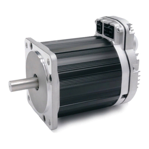
Teknic ClearPath-SCSK Series User manual

U
SER
M
ANUAL
T
EKNIC
,
I
NC
T
EL
.
(585)
784-7454
C
LEAR
P
ATH
-SC
M
OTORS
M
ODELS
SCSK
AND
SCHP
IN
NEMA
23
AND
NEMA
34
F
RAME
S
IZES
V
ERSION
1.36
M
ARCH
17,
2020

C
LEAR
P
ATH
-SC
U
SER
M
ANUAL
R
EV
.
1.36
2
T
EKNIC
,
I
NC
. T
EL
.
(585)
784-7454
T
HIS PAGE INTENTIONALLY LEFT BLANK

C
LEAR
P
ATH
-SC
U
SER
M
ANUAL
R
EV
.
1.36
3
T
EKNIC
,
I
NC
. T
EL
.
(585)
784-7454
T
ABLE OF
C
ONTENTS
T
ABLE OF
C
ONTENTS
...................................................3
Q
UICK
S
TART
G
UIDE
....................................................6
About ClearPath-SC...........................................................6
Who Should Use ClearPath-SC Motors?...........................6
Please Read This Important Warning!..............................6
Description of System Components..............................................7
System Diagram.................................................................7
SC4-HUB............................................................................7
DC Bus Power Supply........................................................7
POWER4-HUB ..................................................................7
Parts of a ClearPath-SC Motor ..........................................8
System Setup..................................................................................9
1. Install ClearView Software.............................................9
2. Install the SC Hub "End-Of-Loop" Jumper ................10
3. Connect ClearPath-SC System Components................11
4. Test the DC Bus Power Polarity................................... 14
5. Establish Communication (USB or RS-232 / Serial).. 15
Test Spin Your Motors Using ClearView.....................................18
S
AFETY
W
ARNINGS
...................................................19
Personal Safety Warnings............................................................19
CE Compliance Warnings............................................................ 19
General Disclaimer ......................................................................20
I
NTRODUCTION
..........................................................21
What is ClearPath-SC?.................................................................21
Parts of a ClearPath-SC Motor ....................................................23
E
XAMPLE
C
LEAR
P
ATH
-SC
S
YSTEMS
.......................... 24
Typical 4-Axis System (Single Port, 1 SC4-HUB) .......................24
Medium System (Single Port, 3 SC4-HUBs)...............................25
Large System (Multiple Ports and SC4-HUBs)...........................26
P
OWERING A
C
LEAR
P
ATH
-SC.................................... 27
Selecting a DC Bus Power Supply................................................27
FAQ: "What size power supply should I use?"................27
Considering a "Lower Voltage" Bus Power Supply?........28
Additional Power Supply Considerations .......................29
Teknic IPC-3 and IPC-5 Power Supplies.....................................30
Teknic Model IPC-3.........................................................30
Teknic Model IPC-5.........................................................30
Before Powering Your ClearPath-SC System .............................. 31
Power Supply Switching and Fusing...............................32
Direct Power Connection.............................................................33
Power Chaining Multiple Motors................................................33
Using the POWER4-HUB............................................................34
POWER4-HUB Overview Diagram.................................34

C
LEAR
P
ATH
-SC
U
SER
M
ANUAL
R
EV
.
1.36
4
T
EKNIC
,
I
NC
. T
EL
.
(585)
784-7454
POWER4-HUB: Things to Know.....................................35
POWER4-HUB: Compliance Notes.................................35
Parts of a POWER4-HUB ................................................36
Connections: One POWER4-HUB ..................................37
Connections: Two POWER4-HUBs.................................38
Auxiliary (24V) Logic Power Supply ...............................39
POWER4-HUB LEDs...................................................... 40
C
OMMUNICATION AND
I/O
(T
HE
SC4-HUB).................41
Introduction.................................................................................41
SC4-HUB Overview .....................................................................41
Parts of an SC4-HUB ...................................................................42
SC4-HUB Mounting.....................................................................42
SC4-HUB Operation (Connector by Connector).........................42
24VDC Input / Passthrough Connectors.........................42
USB Communication Connector (USB Comms).............42
ClearPath I/O Connector.................................................43
End-of-loop Headers .......................................................43
Input A and B Connectors ...............................................44
Brake Control Connectors ...............................................46
Global Stop Connector.....................................................49
Safety Controls Concept Sketch.......................................50
C
ONFIGURATION
S
OFTWARE
(C
LEAR
V
IEW
)..................51
Minimum System Requirements................................................. 51
Installing ClearView Software ..................................................... 51
Establishing Communication With Your System........................52
ClearView Software Tour.............................................................52
User Interface Overview ..................................................52
Manual Motor Controls ...................................................53
Dashboard........................................................................54
Soft Scope.........................................................................55
ClearView Menus............................................................ 60
U
SING THE
D
IAGNOSTIC
C
HANNEL
...............................76
Terms Used in this Section..........................................................76
Connecting to the Diagnostic Channel........................................77
Changing Diagnostic Channel Access Modes..................79
Troubleshooting Diagnostic Channel Connections........ 80
S
OFTWARE
L
IBRARY AND
SDK
O
VERVIEW
..................81
Introduction to the sFoundation Library....................................81
sFoundation Class Hierarchy ......................................................81
INode (Node Level Classes).............................................84
IPort (Port Level Classes)................................................85
SysManager (System Level Class) ...................................86
Software Development Kit (SDK)....................................87
A
PPENDIX
A:
M
OTOR
LED
B
LINK
C
ODES
....................88
A
PPENDIX
B:
M
ECHANICAL
I
NDEX
...............................89
Mounting Dimensions: ClearPath-SC NEMA 34........................89
Mounting Dimensions: ClearPath-SC NEMA 23....................... 90
Motor Mounting, Thermal Considerations.................................91
Mounting Dimensions: SC Hub...................................................92

C
LEAR
P
ATH
-SC
U
SER
M
ANUAL
R
EV
.
1.36
5
T
EKNIC
,
I
NC
. T
EL
.
(585)
784-7454
Mounting Dimensions: Power Hub.............................................93
Connecting ClearPath-SC to a Mechanical System.....................94
Motor Connection: General Tips and Guidelines ...........94
Notes on Coupling Selection............................................96
Installing Pulleys and pinions .........................................97
About End-of-Travel Stops..........................................................98
Hard Blocks......................................................................98
Elastomeric (rubber) Stops .............................................98
Pneumatic (dashpots)......................................................98
End Stops and Hard Stop Homing..................................98
Fan Mounting and Cooling..........................................................99
A
PPENDIX
C:
C
ONNECTOR
M
ATING
P
ARTS
............... 100
A
PPENDIX
D:
S
PECIFICATIONS
.................................. 101
ClearPath-SC Motor: Common Specifications.......................... 101
POWER4-HUB Specifications...................................................103
SC4-HUB Specifications............................................................104
A
PPENDIX
E:
G
ROUNDING AND
S
HIELDING
................ 105
Protective Earth (PE) Connection.............................................105
Grounding and Shielding...........................................................105
Power Returns ...........................................................................106
A
PPENDIX
F:
C
IRCUIT
S
CHEMATICS
.......................... 107
POWER4-HUB Schematic (simplified).....................................107
SC4-HUB Schematic (simplified)..............................................108
A
PPENDIX
G:
W
IRING THE
I
NPUTS
............................. 110
Wiring a Mechanical Switch to an Input................................... 110
Wiring a 24V NPN Sensor to an Input...................................... 110
Application Example: Wiring an Optical Sensor to an Input....111
A
PPENDIX
H:
M
OTOR
P
ART
N
UMBER
K
EY
................. 112
A
PPENDIX
I:
L
OGIC
P
OWER
S
UPPLY
S
IZING
............... 113
A
PPENDIX
J:
H
OW TO
M
AKE A
24V
L
OGIC
S
UPPLY
C
ABLE
............................................................................... 114
A
PPENDIX
K:
C
LEAR
P
ATH
-SC
C
ABLE
P
INOUTS
........ 115
CPM-CABLE-CTRL-MU120.......................................................115
CPM-CABLE-CTRL-MM660......................................................115
CPM-CABLE-PWR-MM660.......................................................116
CPM-CABLE-PWR-MS120.........................................................116

C
LEAR
P
ATH
-SC
U
SER
M
ANUAL
R
EV
.
1.36
6
T
EKNIC
,
I
NC
. T
EL
.
(585)
784-7454
Q
UICK
S
TART
G
UIDE
This section was created to help users achieve the following objectives:
•Understand the ClearPath-SC system at a high level
•Connect the ClearPath-SC system components
•Install ClearView setup and configuration software
•Establish communication between a ClearPath-SC motor and PC
•Spin a ClearPath-SC motor using ClearView software
A
BOUT
C
LEAR
P
ATH
-SC
Thank you for choosing the ClearPath-SC all-in-one servo system with full
software control. ClearPath-SC gives you the highest level of flexibility and
control over your motors and machine application software, because you
write it.
In the ClearPath-SC development model, Teknic provides you with the
sFoundation, an advanced motion software library. ClearPath-SC is
compatible with C++ for Windows/Linux and .NET languages (such as
C#) for Windows. You write the machine application using development
tools like Microsoft Visual Studio.
The included ClearView configuration and setup software, allows
non-software personnel to tune, test, and exercise the servos right on the
machine without coding a single line.
W
HO
S
HOULD
U
SE
C
LEAR
P
ATH
-SC
M
OTORS
?
ClearPath-SC users should be proficient in a programming
language supported by ClearPath, such as C++ for
Windows/Linux and .NET languages (such as C#) for Windows.
If you're not a strong coder, consider ClearPath-MC or ClearPath-SD
motors for your project. The ClearPath-MC family features an
assortment of preprogrammed operating modes, simplified digital
controls, and requires no coding. The ClearPath-SD family accepts
standard step and direction or quadrature AB control signals from any
compatible controller, indexer, or similar device.
P
LEASE
R
EAD
T
HIS
I
MPORTANT
W
ARNING
!
Always use caution and common sense when handling motion control
equipment. Even the smallest ClearPath motor is powerful enough to
crush fingers, tear off a shirt sleeve, or pull out a patch of hair faster than
the blink of an eye1. These devices are extremely powerful and
dangerous if used carelessly, so please read and follow all safety
warnings in the ClearPath-SC User Manual before operating a ClearPath
motor.
1The average duration for a single blink of the human eye is 100 to 400 milliseconds
according to the Harvard Database of Useful Biological Numbers.

C
LEAR
P
ATH
-SC
U
SER
M
ANUAL
R
EV
.
1.36
7
T
EKNIC
,
I
NC
. T
EL
.
(585)
784-7454
D
ESCRIPTION OF
S
YSTEM
C
OMPONENTS
This section provides a brief overview and description of the main
components of a ClearPath-SC system. See the ClearPath-SC User Manual
for more information and specifications on system components.
S
YSTEM
D
IAGRAM
Windows
(or Linux)
SC Hub
Power Hub
ClearPath-SC
Motors
Power-off brake
control connector
Global Stop input
connector
RS-232
USB 2.0
Hi-speed
Application PC
Inputs from motion
related sensors
(connected through to
each CPM-SC)
Distributes bus
power and aux.
“logic backup”
power to motors
DC Bus
Power Supply
(24-75VDC)
24VDC Supply
24VDC Supply
A 4-axis ClearPath-SC System
SC4-HUB
The SC4-HUB connects your computer and I/O devices to your ClearPath-
SC motors. The SC Hub routes communication signals, passes
sensor/switch inputs to the motors, includes 2 power-off brake outputs ,
and one Global Stop (e-stop) input. A maximum of 4 SC Hubs can be
linked together to create systems of up to 16 axes per port, and up to 3
ports per computer, allowing you to create systems with as many as 48
motion axes.
DC
B
US
P
OWER
S
UPPLY
The DC Bus Power Supply provides main power to your ClearPath-SC
motors. A Teknic IPC-5, 75VDC supply is shown above, but ClearPath-SC
motors can be powered from other supplies in the 24–75VDC range.
POWER4-HUB
The POWER4-HUB distributes DC bus power and backup logic power to
as many as four ClearPath-SC motors per hub. If DC bus power is
suddenly lost, the Power Hub will automatically switch to auxiliary logic
power to maintain uninterrupted power to the processor, memory, and
communication circuits. Multiple Power Hubs can be chained together to
support larger systems.

C
LEAR
P
ATH
-SC
U
SER
M
ANUAL
R
EV
.
1.36
8
T
EKNIC
,
I
NC
. T
EL
.
(585)
784-7454
P
ARTS OF A
C
LEAR
P
ATH
-SC
M
OTOR
Industry-leading, programmable, brushless servo motor with precision
optical encoder, built in controller, trajectory generator, servo
compensator, and torque drive.
Diagnostic Port
(USB micro-B)
DC Bus Power Connector
(Molex Minifit Jr. 4 position) Auxilliary PE
(Protective Earth)
Connection Point
ClearPath I/O Connector
(Molex Minifit Jr. 8 position)
Stainless
Steel Shaft
NEMA
Mounting
Flange
Die Cast
Heatsink
Sealing
Gasket
Housing
(Anodized aluminum)
Keyway
Status LED
Silicone Plug
(Covers diag. port)
Parts of a ClearPath-SC motor

C
LEAR
P
ATH
-SC
U
SER
M
ANUAL
R
EV
.
1.36
9
T
EKNIC
,
I
NC
. T
EL
.
(585)
784-7454
S
YSTEM
S
ETUP
This section describes how to connect ClearPath-SC components, apply
power, and establish communication with your PC. We'll show you how to
run some basic test moves in the next section.
R
EAD
T
HIS
B
EFORE
P
OWERING
U
P A
C
LEAR
P
ATH
-SC
S
YSTEM
•Do secure your motors to a stable work surface.
•Do keep loose items such as cables, hair, and clothing away from
motor shafts.
•Do observe static-safe handling practices when handling the SC
Hub and Power Hub.
•Do not "hot swap" power connectors (i.e. don't connect or
disconnect DC power connectors when the DC Bus Supply is
powered up). This will cause electrical arcing, carbon scoring, and
pitting of the terminals over time.
•Do install a protective (finger-safe) guard (or other physical
barrier) around the motor shaft.
1.
I
NSTALL
C
LEAR
V
IEW
S
OFTWARE
1. Update your Windows installation. See note below for details.
2. Download the ClearView installer from Teknic's website:
https://www.teknic.com/downloads/
3. Launch the ClearView Installer. Follow the on-screen prompts.
Important Software Installation Note
If your Windows installation is not up to date, ClearView may not run
properly on your PC. During installation, the ClearView installer needs
access to a few specific Windows system files. If these files are not found,
Windows Update will attempt to install them. If Windows Update is
disabled, and/or you have no internet connection, this may fail.
If you install and attempt to run ClearView and see an error window like
the one shown above, close ClearView and install this update:
https://support.microsoft.com/en-us/kb/2999226. Then, re-launch
ClearView.

C
LEAR
P
ATH
-SC
U
SER
M
ANUAL
R
EV
.
1.36
10
T
EKNIC
,
I
NC
. T
EL
.
(585)
784-7454
2.
I
NSTALL THE
SC
H
UB
"E
ND
-O
F
-L
OOP
"
J
UMPER
Place one (and only one) jumper block on the 2-pin header associated
with the last motor connected to your SC Hub. Motors must be populated
in order from CP0 to CP3 (do not skip motor locations or the system will
not communicate properly). Place the jumper on J0 for a single motor, on
J1 for two motors, and so forth. See the diagram below for details.
CP3
0A 1A 1B 2B 3A
CP0
OPEN
CP2
CP1
0B 2A 3B
+ 24V -
GLOBAL STOP
First motor always
connects here
DATA
DB9R-M
DB9R-F
24V Input
J0 J1 J2 J3 J5
Place one jumper per SC Hub only!
Place jumper
here for one
motor
Place jumper
here for two
motors
Place jumper
here for three
motors
Place jumper
here for four
motors
Place jumper
here if you add
another SC Hub
(5 or more motors)
SC4-HUB jumper placement
Note: If you connect a second SC Hub, place one jumper at J5 on the first
SC Hub. Then, on the second SC Hub, place one jumper at the last
populated motor location.

C
LEAR
P
ATH
-SC
U
SER
M
ANUAL
R
EV
.
1.36
11
T
EKNIC
,
I
NC
. T
EL
.
(585)
784-7454
3.
C
ONNECT
C
LEAR
P
ATH
-SC
S
YSTEM
C
OMPONENTS
Before applying power, connect all ClearPath-SC components as
shown in the hookup diagrams later in this section.
Note: Because the Power Hub component is optional, there are two
different versions of the hookup diagram included in this section. Please
refer to the diagram that most closely matches your system.
24
V
OLT
L
OGIC
P
OWER
S
UPPLY
The SC Hub, Power Hub, and other optional components require a 24VDC
nominal power supply to operate. In a small ClearPath SC system (4 axes
or fewer) a 50-75 watt logic supply should suffice.
For help estimating how much power (watts) your logic power supply
must be rated for, see the appendix "Logic Power Supply Sizing".
Tip: See Appendix J for instructions on how to make an inexpensive, no-
crimp power cable for your logic supply.

C
LEAR
P
ATH
-SC
U
SER
M
ANUAL
R
EV
.
1.36
12
T
EKNIC
,
I
NC
. T
EL
.
(585)
784-7454
S
YSTEM
H
OOKUP
D
IAGRAM
(W
ITH A
P
OWER
H
UB
)
Axis 0Axis 1Axis 2Axis 3
75VDC IN
75VDC OUTPUTS
(4 per Power Hub)
Global Stop
Connector
Brake or
GP Outputs
75VDC
(BUS IN) COMM
& I/O
24VDC
Pass-through
Expansion
Connector
Inputs
(2 per axis)
USB-B
RS-232
(DB-9)
OR
Windows
(or Linux)
AXIS 0AXIS 1
24VDC
Supply
Power Hub SC Hub
Teknic IPC-5
75VDC Power Supply
ClearPath-SC Motors
AC SOURCE
110/220VAC
75VDC
OUTPUTS
24VDC IN
Ref. Cable Part Number Description
ACPM-CABLE-CTRL-MU120
Cable assembly, 120" ClearPath I/O
(overmolded Molex Minifit 8-pin to standard
Molex Minifit 8-pin).
BCPM-CABLE-M2P2P-120
2-pin Molex to 2-pin Molex multi-purpose
cable, ~10 ft long.
CCPM-CABLE-PWR-MS120
Cable assembly, 120" ClearPath PWR (Minifit
4 over molded Molex to Sabre).
DCPM-CABLE-USB-120AB
ClearPath USB Cable; A-male to B-male. 120
inches (3.05m) in length
ECPM-CABLE-USB-120
ClearPath USB Cable; A-male to Micro-B.120
inches (3.05m) in length.
FIPC35-CABLE110
AC Line Cord (110V) for Amazon IPC-3 and
IPC-5 power supplies. Includes NEMA 5-15P
to Minifit 8 pin connector, 78.25 inches in
length (nominal).
GPC-SBR-72
Power cable, Sabre to Sabre, 72".
AA
B
F
G
C C
ClearPath-SC Hookup Diagram (for systems with a Power Hub)

C
LEAR
P
ATH
-SC
U
SER
M
ANUAL
R
EV
.
1.36
13
T
EKNIC
,
I
NC
. T
EL
.
(585)
784-7454
S
YSTEM
H
OOKUP
D
IAGRAM
(W
ITHOUT
P
OWER
H
UB
)
Axis 0Axis 1Axis 2Axis 3
Global Stop
Connector
75VDC OUT
24VDC
Pass-through
75VDC
(BUS IN) COMM
& I/O
Brake or
GP Outputs
Expansion
Connector
Inputs
(2 per axis)
F
USB-B
RS-232
(DB-9)
OR
Windows
(or Linux)
AXIS 0AXIS 1
SC Hub
Teknic IPC-5
75VDC Power Supply
ClearPath-SC Motors
AC SOURCE
110/220VAC
75VDC
OUTPUTS
24VDC
Supply
Ref. Cable Part Number Description
A
CPM-CABLE-CTRL-MU120
Cable assembly, 120" ClearPath I/O
(overmolded Molex Minifit 8-pin to standard
Molex Minifit 8-pin).
B
CPM-CABLE-M2P2P-120
2-pin Molex to 2-pin Molex multi-purpose
cable, ~10 ft long.
C
CPM-CABLE-PWR-MS120
Cable assembly, 120" ClearPath PWR (Minifit
4 over molded Molex to Sabre).
D
CPM-CABLE-USB-120AB
ClearPath USB Cable; A-male to B-male. 120
inches (3.05m) in length
E
CPM-CABLE-USB-120
ClearPath USB Cable; A-male to Micro-B.120
inches (3.05m) in length.
F
IPC35-CABLE110
AC Line Cord (110V) for Amazon IPC-3 and
IPC-5 power supplies. Includes NEMA 5-15P
to Minifit 8 pin connector, 78.25 inches in
length (nominal).
G
PC-SBR-72
Power cable, Sabre to Sabre, 72".
AA
C
C
ClearPath-SC Hookup Diagram (for systems without a Power Hub)

C
LEAR
P
ATH
-SC
U
SER
M
ANUAL
R
EV
.
1.36
14
T
EKNIC
,
I
NC
. T
EL
.
(585)
784-7454
4.
T
EST THE
DC
B
US
P
OWER
P
OLARITY
Before applying DC bus power to your motor, please perform this quick
test. It is well worth the few minutes it takes, and may save you significant
amounts of time, money, and frustration.
IMPORTANT: Reversing DC Bus polarity will permanently damage your
ClearPath-SC motors.
1. Start with the 4-pin power connector disconnected from your
ClearPath-SC motor and the AC unplugged.
2. Power up your DC Bus Power Supply.
3. With a DMM, measure the voltage from V+ to GND. See diagram
below for pin locations. You should measure a positive value of
DC voltage. (The actual voltage measured depends on your
supply.) If you measure a negative value, the polarity is
reversed. Fix the problem and measure again.
4. Remove power from your supply.
5. Reconnect the 4-pin power connector to your ClearPath-SC motor
and power up.
IMPORTANT: CHECK DC BUS VOLTAGE POLARITY!
POWER CONNECTOR
Front view
GND
GND
V+
V+
GND
V+
GND
V+
POWER CONNECTOR
Wire entry view
2
4
2
4
1
3
1
3
VDC
Clearpath operating
voltage range: 24-75VDC
Testing polarity of DC Bus

C
LEAR
P
ATH
-SC
U
SER
M
ANUAL
R
EV
.
1.36
15
T
EKNIC
,
I
NC
. T
EL
.
(585)
784-7454
5.
E
STABLISH
C
OMMUNICATION
(USB
OR
RS-232
/
S
ERIAL
)
Next, you'll need to establish communication between your PC and the
ClearPath-SC motors you want to control. There are two communication
protocols available, USB or RS-232. Each is described in this section.
USB
C
OMMUNICATION
1. Power up your ClearPath-SC system.
2. Connect USB cable from the SC Hub to your PC. This is a
standard USB-A (male) to USB-B (male) cable.
USB-A (male) to USB-B (male)
3. Wait! Allow the drivers to auto-install. This may take a minute.
4. Launch the ClearView software.
5. ClearView will immediately attempt to auto-detect your motors. If
all is well, you will see your motor(s) appear in the Motor List in
ClearView.
Motor List showing
two motors connected
to an SC Hub. Success!
Two ClearPath-SC motors recognized in ClearView
6. If ClearView does not auto-detect your motors. Follow the steps
described in Setting the USB COM Port Manually, below.
Setting the USB COM Port Manually
1. Open Device Manager (Windows systems).
2. Double-click "Ports (COM & LPT)".

C
LEAR
P
ATH
-SC
U
SER
M
ANUAL
R
EV
.
1.36
16
T
EKNIC
,
I
NC
. T
EL
.
(585)
784-7454
3. Under Ports, locate "Teknic ClearPath 4-Axis Comm Hub
(COM[n])". Take note of the value [n]—this is your COM port
number.
4. In ClearView software go to File>Preferences.
5. Click the drop down menu in the section labeled "First".
6. Select the COM port [n] you identified above. Click "Done".
Select "Teknic ClearPath 4-axis Comm Hub" for First COM port

C
LEAR
P
ATH
-SC
U
SER
M
ANUAL
R
EV
.
1.36
17
T
EKNIC
,
I
NC
. T
EL
.
(585)
784-7454
RS-232,
S
ERIAL
C
OMMUNICATION
Important: If you choose serial communication, your serial port must
support a minimum of 230k baud to run ClearView software. If you
do not know what speeds are supported by your serial port, check
Windows Device Manager under Ports, or refer to your computer's
documentation.Note: Applications running without ClearView will run
properly down to 115k baud minimum.
If you want to use serial communication, and your serial ports aren't fast
enough, you can find high speed serial port cards online from companies
such as Axxon (softio.com) and Perle.
1. Power up your ClearPath-SC system.
2. Connect your serial communication cable (DB-9 to DB-9,
straight-through) from the SC Hub to your PC.
3. Launch the ClearView application.
4. Click File>Preferences. A dialog box will pop up. In the section
labeled "First", select the COM port number assigned to the serial
port you are using.
5. Click "Done".

C
LEAR
P
ATH
-SC
U
SER
M
ANUAL
R
EV
.
1.36
18
T
EKNIC
,
I
NC
. T
EL
.
(585)
784-7454
T
EST
S
PIN
Y
OUR
M
OTORS
U
SING
C
LEAR
V
IEW
Note: This section describes how to spin an unloaded motor (i.e. a motor
with nothing attached to the shaft). Important: ClearPath-SC motors ship
out pre-configured for unloaded use only. You must run the Auto-
Tune application whenever you connect your motor to a
different mechanical system.
Click and spin—no code required! Once your system is powered up
and communicating, you can take your motors for a test spin using
ClearView's Move Generator or Jog Motion controls. Here's how:
1. Select the motor you'd like to spin from the Motor List.
2. Set the Move Type: Back and Forth, Single, or Repeating.
3. Enter the Move Parameters: Distance, Velocity, Acceleration, and
Dwell (Dwell is just the rest period between repeating moves).
4. Click Enable/Disable button once to enable the motor.
5. Click "Start Motion" (+ or -) button. Hit "+" to start motion in the
counter clockwise direction; hit "-" to start motion in the
clockwise direction
6. Single click the "Stop" button to end motion cycling. Double click
the Stop button to stop motion immediately.
7. Click "E-Stop All" or hit your Esc key to stop motion immediately.
Enable/Disable
Motor Move Type Active Motor
E-Stop
Move
Parameters
START Motion
plus(+) = CCW
minus (-) = CW
STOP MOTION
1
2
3
4
56
7
ClearView Main UI
------End Quick Start Guide------

C
LEAR
P
ATH
-SC
U
SER
M
ANUAL
R
EV
.
1.36
19
T
EKNIC
,
I
NC
. T
EL
.
(585)
784-7454
S
AFETY
W
ARNINGS
IMPORTANT: Read this manual before attempting to install, power up,
or operate a ClearPath motor. Failure to understand and follow the safety
information presented in this document could result in property damage,
bodily injury, or worse.
P
ERSONAL
S
AFETY
W
ARNINGS
•Do not wear loose clothing or unconfined long hair when using
ClearPath-SC motors. Remove ties, rings, watches and other
jewelry before operating an unguarded motor.
•Do not operate a ClearPath-SC motor if your alertness, cognitive
function, or motor skills are impaired.
•Always handle, and carry a ClearPath-SC motor by the housing
(don’t carry it by the shaft or cable). Be aware that in certain
scenarios ClearPath-SC is may spin as soon as main DC power is
applied.
•Always understand how to use ClearPath-SC software controls
and associated features before attempting to power, enable, or
otherwise operate a ClearPath-SC motor.
•Install and test all emergency stop devices and controls before
using ClearPath-SC.
•Before applying DC power, secure the ClearPath-SC motor to a
stable, solid work surface and install a finger-safe guard or barrier
between the user and the motor shaft.
•Provide appropriate space around the ClearPath-SC motor for
ventilation and cable clearances.
•Do not allow cables or other loose items to drape over, or rest near
the ClearPath-SC motor shaft.
•Never place fingers, hands, or other body parts on or near a
powered ClearPath-SC motor.
•Thoroughly test all ClearPath-SC applications at low speed to
ensure the motor, controls, and safety equipment operate as
expected.
CE
C
OMPLIANCE
W
ARNINGS
•There are no user serviceable parts inside.
•Follow all instructions and use the product only as directed.
•Safety of any system incorporating this equipment is the
responsibility of the system designers and builders.
•The machine designers need to recognize and incorporate
required warning symbols, guards and shields for ClearPath-SC
motors that are used in applications that can result in the
external accessible parts of their machine exceeding a

C
LEAR
P
ATH
-SC
U
SER
M
ANUAL
R
EV
.
1.36
20
T
EKNIC
,
I
NC
. T
EL
.
(585)
784-7454
temperature of 65 Celsius. This is required as a method to
reduce burns. A tool shall be required to remove any guards
and/or shields.
•ClearPath-SC motors require that a path exist between the
motor chassis and the Protective Earth (PE) connection of the
machine to which it is affixed. (Note: The PE connection is often
satisfied by simply bolting the motor to the machine; however it
is the users responsibility to verify the PE connection.) If an
external grounding wire is required, use the same or larger wire
gauge as used between the DC power supply and ClearPath
Motor.
•Any maintenance or repair guide created by the user shall state
that power shall be removed before the Protective Earth ground
conductor is disconnected. When reconnecting power, the
Protective Earth ground conductor shall be the first wire
reconnected. Main power may be reconnected only after the
Safety Ground connection is secure.
•When the ClearPath-SC motor is mounted in an application
where the shaft end is higher than the electrical connection end
of the motor, the USB connector plug provided by Teknic must
be installed. The USB plug in these installations becomes an
element to prevent the spread of fire per EN 61010-1 section
9.3.2 part c.
G
ENERAL
D
ISCLAIMER
The User is responsible for determining the suitability of products for their different
applications. The User must ensure that Teknic's products are installed and utilized in
accordance with all local, state, federal and private governing bodies and meet all
applicable health and safety standards.
Teknic has made all reasonable efforts to accurately present the information in the
published documentation and shall not be responsible for any incorrect information which
may result from oversights. Due to continuous product improvements, the product
specifications as stated in the documentation are subject to change at any time and
without notice. The User is responsible for consulting a representative of Teknic for
detailed information and to determine any changes of information in the published
documentation.
If Teknic’s products are used in an application that is safety critical, the User must provide
appropriate safety testing of the products, adequate safety devices, guarding, warning
notices and machine-specific training to protect the operator from injury.
This manual suits for next models
3
Table of contents
Other Teknic Engine manuals
