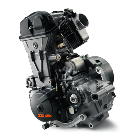
KTM S5-E Operating instructions

MOTORCYCLES
REPARATURANLEITUNG MOTOR
REPAIR MANUAL ENGINE
MANUEL DE RÉPARATION MOTEUR
S5-E / S5-T / S5-GS
3.97
ART. NR. 3.205.19
´97

ENGLISH
1
INTRODUCTION
THIS REPAIR MANUAL OFFERS EXTENSIV REPAIR-INSTRUCTIONS AND IS AN UP-TO-DATE VERSION THAT DESCRIBES THE LATEST MODELS OF
THE SERIES. HOWEVER, THE RIGHT TO MODIFICATIONS IN THE INTEREST OF TECHNICAL IMPROVEMENT IS RESERVED WITHOUT UPDATING
THE CURRENT ISSUE OF THIS MANUAL.
A DESCIRIPTION OF GENERAL WORKING MODES COMMON IN WORK SHOPS HAS NOT BEEN INCLUDED. SAFETY RULES COMMON IN THE
WORK SHOP HAVE ALSO NOT BEEN LISTED. WETAKE IT FOR GRANTED THAT THE REPAIRS ARE MADE BY QUALIFIED PROFESIONALLY TRAI-
NED MECHANICS.
READ THROUGH THE REPAIR MANUAL BEFORE BEGINNING WITH THE REPAIR WORK.
WARNING
STRICT COMPLIANCE WITH THESE INSTRUCTIONS IS ESSENTIAL
TO AVOID DANGER TO LIFE AND LIMB.
!
CAUTION
!
NON-COMPLIANCE WITH THESE INSTRUCTIONS CAN LEAD TO
DAMAGE OF MOTORCYCLE COMPONENTS OR RENDER MOTORCY-
CLES UNFIT FOR TRAFFIC !
„NOTE” POINTS OUT USEFUL TIPS.
USE ONLY ORIGINAL KTM SPARE PARTS WHEN REPLACING PARTS.
THE ENGINE IS ONLY ABLE TO MEET USER EXPECTATIONS IF THE MAINTENANCE WORK IS PERFORMED REGULARLY AND PROFESSIONALLY.
FOR TECHNICAL DATA SEE LAST SECTION OF THIS MANUAL. UP-TO-DATE INFORMATION IS PUBLISHED IN OUR UPDATED SPARE PARTS CATA-
LOGUES.
KTM AUSTRIA’SCERTIFICATE OF ACHIEVEMENT FOR ITS QUALITY SYSTEM ISO 9001 IS THE BEGINNING OF AN ON- GOING TOTAL RE-
ENGINEERED QUALITY PLAN FOR A BRIGHTER TOMORROW.
KTM SPORTMOTORCYCLE AKTIENGESELLSCHAFT
5230 MATTIGHOFEN, AUSTRIA
ALL DESIGN AND ASSEMBLY MODIFICATION RIGHTS RESERVED.

ENGLISH
2
Page
1.0 SPECIAL TOOLS . . . . . . . . . . . . . . . . . . . . . . . . . . . . . . . . . .3
2.0 REMOVING THE ENGINE . . . . . . . . . . . . . . . . . . . . . . . . . .3
3.0 DISASSEMBLING THE ENGINE . . . . . . . . . . . . . . . . . . . . . .4
3.1 Draining the gear oil . . . . . . . . . . . . . . . . . . . . . . . . . . . . . . . . .4
3.2 Ignition . . . . . . . . . . . . . . . . . . . . . . . . . . . . . . . . . . . . . . . . . .4
3.3 Engine sprocket . . . . . . . . . . . . . . . . . . . . . . . . . . . . . . . . . . . .5
3.4 Cylinder head, cylinder . . . . . . . . . . . . . . . . . . . . . . . . . . . . . . .5
3.5 Piston . . . . . . . . . . . . . . . . . . . . . . . . . . . . . . . . . . . . . . . . . . .6
3.6 Kickstarter . . . . . . . . . . . . . . . . . . . . . . . . . . . . . . . . . . . . . . . .6
3.7 Clutch, primary drive . . . . . . . . . . . . . . . . . . . . . . . . . . . . . . . .7
3.8 Separating the two housing halves . . . . . . . . . . . . . . . . . . . . . . .8
3.9 Crankshaft, countershaft . . . . . . . . . . . . . . . . . . . . . . . . . . . . . .8
4.0 WORK ON INDIVIDUAL COMPONENTS . . . . . . . . . . . . . . .9
4.1 Left housing half . . . . . . . . . . . . . . . . . . . . . . . . . . . . . . . . . . . .9
4.2 Right housing half . . . . . . . . . . . . . . . . . . . . . . . . . . . . . . . . . . .9
4.3 Piston . . . . . . . . . . . . . . . . . . . . . . . . . . . . . . . . . . . . . . . . . .10
4.3.1 Checking the piston ring end gap . . . . . . . . . . . . . . . . . . . . . . .10
4.4 Measuring piston and cylinder, piston fitting clearance . . . . . . . . . .10
4.5 Crankshaft . . . . . . . . . . . . . . . . . . . . . . . . . . . . . . . . . . . . . . .11
4.6 Reed valve housing (S5-T) . . . . . . . . . . . . . . . . . . . . . . . . . . . .11
4.6.1 Reed valve housing (S5-GS) . . . . . . . . . . . . . . . . . . . . . . . . . . .11
4.7 Clutch cover . . . . . . . . . . . . . . . . . . . . . . . . . . . . . . . . . . . . . .12
4.8 Kickstarter shaft . . . . . . . . . . . . . . . . . . . . . . . . . . . . . . . . . . .12
4.8.1 Preassembling of kickstarter shaft . . . . . . . . . . . . . . . . . . . . . . .13
4.9 Centrifugal clutch, primary drive . . . . . . . . . . . . . . . . . . . . . . .13
4.10 Exchanging the clutch shoes . . . . . . . . . . . . . . . . . . . . . . . . . .13
5.0 ASSEMBLING THE ENGINE . . . . . . . . . . . . . . . . . . . . . . . .14
5.1 Mounting the crankshaft . . . . . . . . . . . . . . . . . . . . . . . . . . . . .14
5.2 Assembling the housing . . . . . . . . . . . . . . . . . . . . . . . . . . . . . .14
5.3 Engine sprocket . . . . . . . . . . . . . . . . . . . . . . . . . . . . . . . . . . .14
5.4 Chain securing guide . . . . . . . . . . . . . . . . . . . . . . . . . . . . . . . .14
5.5 Mount flywheel . . . . . . . . . . . . . . . . . . . . . . . . . . . . . . . . . . .14
5.6 Mount and set the ignition coil . . . . . . . . . . . . . . . . . . . . . . . .15
5.7 Piston, cylinder . . . . . . . . . . . . . . . . . . . . . . . . . . . . . . . . . . . .16
5.8 Cylinder head . . . . . . . . . . . . . . . . . . . . . . . . . . . . . . . . . . . . .16
5.9 Primary drive, clutch . . . . . . . . . . . . . . . . . . . . . . . . . . . . . . . .16
5.10 Kickstarter . . . . . . . . . . . . . . . . . . . . . . . . . . . . . . . . . . . . . . .17
5.11 Gear oil . . . . . . . . . . . . . . . . . . . . . . . . . . . . . . . . . . . . . . . . .18
6.0 INSTALLING THE ENGINE . . . . . . . . . . . . . . . . . . . . . . . . .18
7.0 TECHNICAL DATA - ENGINE . . . . . . . . . . . . . . . . . . . . . . .19
7.1 Tolerances and fitting clearances . . . . . . . . . . . . . . . . . . . . . . .20
7.2 Tightening torques . . . . . . . . . . . . . . . . . . . . . . . . . . . . . . . . .20
7.3 Basic carburetor setting . . . . . . . . . . . . . . . . . . . . . . . . . . . . . .20
8.0 PERIODIC MAINTENANCE SCHEDULE . . . . . . . . . . . . . .21
INDEX
ENGLISH
3
–Clean motorcycle
–Remove seat, subframe and fuel tank.
–Remove exhaust pipe, carburetor and chain.
–Disconnect the cable of the short circuit button.
–Remove engine screws, engine supports and carefully take engine out of the
frame on the right side.
1.0 SPECIAL TOOLS
2.0 REMOVING THE ENGINE
100
35
15
8
2
3
4
15
FIG. DESCRIPTION PART NR.
1Holding wrench for flywheel and clutch hub 151.12.021.000
2Extractor for clutch hub and primary gear 160.12.005.000
3Loctite 242 blue 6.899.785
4Extractor for flywheel 151.12.009.000
5Engine holder 450.29.001.000

ENGLISH
4
–Secure the engine with two screws (M8 x 45) in the engine holder.
3.1 Draining the gear oil
–Remove the gear oil drain plug 1and the seal ring and drain the gear oil.
3.2 Ignition
–Remove the two retaining springs 2and lift off the ignition cover.
–Take the rubber 3out of the opening in the housing.
–Disconnect the spark plug connector from the spark plug.
–Remove the two screws 4and washers and take off the ignition coil 5.
–Insert the holding wrench 6into the two bores of the flywheel and hold the
flywheel.
–Unscrew the hexagon nut of the flywheel.
3.0 DISASSEMBLING THE ENGINE
1
2
2
3
4
4
5
6

ENGLISH
5
–Mount the extractor and pull off the flywheel.
–Take the woodruff key out of the crankshaft.
!
CAUTION
!
NEVER USE A HAMMER OR A SIMILAR TOOL ON THE FLYWHEEL.
–Remove the 3 screws 1and take off the base plate.
3.3 Engine sprocket
–Remove the Seeger circlip and the washer behind the circlip and pull the engine
sprocket off the countershaft.
–Pull the flywheel rubber 2off.
–Remove screw 3and take off the chain securing guide.
3.4 Cylinder head, cylinder
–Twist out the spark plug.
–
Undo the 4 hexagon nuts and remove the cylinder head with cylinder head gasket.
1
1
2
3

ENGLISH
6
–Lift the cylinder off the studs.
N
OTE
: W
HEN REMOVING THE CYLINDER MAKE SURE THAT THE PISTON DOESN
’
THITTHE HOUSING
.
3.5 Piston
–Place the piston on the wooden fork.
–Remove the piston pin locking devices and push the piston pins out of the piston
without applying force.
–Remove the piston.
–Take the piston pin bearing out of the conrod eye.
3.6 Kickstarter
–Remove screw 1.
–Hold the kickstarter and remove the kickstarter stop screw 2.
–Release the kickstarter spring by releasing the kickstarter.
–Unhook the kickstarter spring 3and pull the kickstarter off the kickstarter shaft.
–Take the plastic cap 4and the kickstarter spring 5off the kickstarter shaft.
1
2
3
5
4

ENGLISH
7
3.7 Clutch, primary drive
–Remove all 7 screws and lift off the clutch cover and the gasket.
NOTE: WHEN REMOVING THE CLUTCH COVER KEEP IN MIND THE STOP DISK OF THE KICK-
STARTER SHAFT (CAN STICK TO THE INSIDE OF THE CLUTCH COVER).
–Hold the clutch hub with the holding wrench and undo nut 1(LH thread).
–Remove nut and washer.
–Mount the extractor and pull off the clutch hub.
–Remove the clutch drum together with the two washers located behind it.
–Hold the primary gear with the holding wrench and undo the hexagon nut.
–Remove hexagon nut and washer.
–Mount the extractor and pull the primary gear off the countershaft.
1

ENGLISH
8
3.8 Separating the two housing halves
–Remove all 7 housing screws and clamp the engine holder together with the
engine sideways into the vise in such a way that the clutch side of the engine is
on top.
–Lightly tap the right housing half with a rubber hammer until the housing half
can be removed.
NOTE: WHEN REMOVING THE HOUSING HALF KEEP IN MIND THE STOP DISK OF THE COUN-
TERSHAFT (CAN STICK TO THE INSIDE OF THE HOUSING).
–Remove the housing gasket.
–Take the stop disk off the countershaft.
!
CAUTION
!
TOPREVENT DAMAGING OF THE SEALING SURFACES, NEVER FORCE THE ENGINE HALVES APART
WITH A SCREWDRIVER OR SIMILAR TOOL.
3.9 Crankshaft, countershaft
–Pull the countershaft 1out of the bearing.
NOTE: A RUBBER HAMMER CAN BE USED ON THE COUNTERSHAFT CAREFULLY IF IT IS NOT POS-
SIBLE TO PULL THE COUNTERSHAFT OUT OF THE BEARING MANUALLY
.
–Carefully tap the crankshaft with a rubber hammer to take it out of the left hou-
sing half.
–Clean all parts and check for damage.
1

ENGLISH
9
4.1 Left housing half
Remove the shaft seal rings and heat the housing half, using a hot plate, to a tem-
perature of approximately 150° C.
GROOVED BALL BEARING OF THE CRANKSHAFT 1
Use a suitable mandrel to press the grooved ball bearing inwards.
Insert a new grooved ball bearing from inside, pressing it all the way into the recess.
GROOVED BALL BEARING OF THE COUNTERSHAFT 2
Use a suitable mandrel to press the grooved ball bearing inwards.
Insert a new grooved ball bearing from inside, pressing it all the way into the recess.
!
CAUTION
!
APPLY ONLY SLIGHT PRESSURE WHEN INSERTING GROOVED BALL BEARING INTO THE HOUSING
SO AS TO PREVENT DAMAGING OF THE HOUSING.
SHAFT SEAL RING OF THE CRANKSHAFT 3
Insert a new shaft seal ring from outside, the sealing lip facing inwards. The seal ring
must be 2 mm (0.08 in.) below the edge of the housing.
SHAFT SEAL RING OF THE COUNTERSHAFT 4
Insert a new shaft seal ring from outside, the sealing lip facing inwards. The seal ring
must be flush with the edge of the housing.
4.2 Right housing half
Remove the shaft seal ring and heat the housing half, using a hot plate, to a tempe-
rature of approximately 150° C.
GROOVED BALL BEARING OF THE CRANKSHAFT 5
Use a suitable mandrel to press the grooved ball bearing inwards.
Insert a new grooved ball bearing from inside, pressing it all the way into the recess.
GROOVED BALL BEARING OF THE COUNTERSHAFT 6
Use a suitable mandrel to press the grooved ball bearing inwards.
Insert a new grooved ball bearing from inside, pressing it all the way into the recess.
!
CAUTION
!
APPLY ONLY SLIGHT PRESSURE WHEN INSERTING GROOVED BALL BEARING INTO THE HOUSING
SO AS TO PREVENT DAMAGING OF THE HOUSING.
ENGINE HOUSING
NOTE: READ THROUGH THE FOLLOWING SECTION BEFORE COMMENCING WORK. THEN DETERMINE IN WHICH ORDER THE PARTS MUST BE MOUNTED TO ENSURE THAT
THE HOUSING HALVES NEED NOT BE HEATED MORE THAN ONCE TO INSERT THE BEARINGS.
BEFORE PRESSING OR - IF NECESSARY - HAMMERING OUT THE BEARINGS, PLACE THE HOUSING HALVES ON A SUFFICIENTLY LARGE PLANE SURFACE (AFTER REMOVING
THE DOWEL PINS). TOPREVENT DAMAGING OF THE SEALING SURFACE, ENSURE THAT THE ENTIRE SEALING SURFACE OF THE HOUSING IS PROPERLY RESTING ON THE
SUPPORTING SURFACE. WERECOMMEND TO PLACE THE HOUSING HALVES ON A WOODEN BOARD.
A MANDREL SHOULD NOT BE USED TO INSERT BEARINGS OR SHAFT SEAL RINGS. HOWEVER, IF A SUITABLE PRESSING DEVICE IS NOT AVAILABLE, AMANDREL CAN BE
USED VERY CAREFULLY TO INSERT BEARINGS OR SHAFT SEAL RINGS. ATAHOUSING TEMPERATURE OF APPROXIMATELY 150° C, THE COLD BEARINGS WILL SLIDE INTO
THEIR SEATS QUITE EASILY ANYHOW
, REQUIRING ALMOST NO ADDITIONAL ATTENTION.
IFTHE BEARINGS ARE NOT LOCKED TIGHT IN THEIR SEATS AFTER COOLING, THEY MUST BE EXPECTED TO CHANGE THEIR POSITION WITHIN THE HOUSING AS THE UNIT
HEATS UP
. INTHIS CASE, THE HOUSING MUST BE REPLACED.
1
2
34
56
4.0 WORK TO BE PERFORMED ON INDIVIDUAL COMPONENTS

ENGLISH
10
SHAFT SEAL RING OF THE CRANKSHAFT 7
Insert a new shaft seal ring from outside, the sealing lip facing inwards. The seal ring
must be 2 mm (0.08 in.) below the edge of the housing.
4.3 Piston
When intending to reinstall a used piston, perform the following checks:
–Check the piston bearing surface for signs of wear (seizing of the piston).
Superficial grooves can be removed using a fine-grained abrasive block.
–The piston rings should not stick in their grooves. To clean the grooves, use an
old piston ring or abrasive paper.
–The piston-ring locking devices 1must fit tightly into the piston and should not
be worn.
–The piston pin should not be discolored or significantly grooved.
4.3.1 Checking the piston ring end gap
–Check the piston rings for signs of wear (grooves).
–Check the piston ring end gap B.
–Align the piston ring with the piston approximately 10 mm (0.4 in.) below the
upper cylinder edge.
–Use a feeler gauge to measure the end gap B.
END GAP: MAX. 0.55 MM (0.022 IN.)
IFTHE END GAP EXCEEDS THIS LIMIT, CHECK PISTON AND CYLINDER FOR WEAR (FOR WEAR
LIMITS REFER TO THE TECHNICAL SPECIFICATIONS). IFBOTH PISTON AND CYLINDER WEAR ARE
WITHIN THE ADMISSIBLE LIMITS, REPLACE THE PISTON RINGS.
4.4 Measuring piston and cylinder, piston fitting clearance
–To determine cylinder wear, measure the cylinder, applying a micrometer to the
middle of the bearing surface.
–Measure the cylinder diameter along both the x-axis and y-axis to determine ova-
lity, if any.
–The piston is measured at the piston skirt at a right angle to the piston pin as
shown in the illustration.
–The piston fitting clearance is the cylinder diameter minus the piston diameter.
PISTON FITTING CLEARANCE (S5-E) : MAX. 0.070 MM (0.0028 IN.)
PISTON FITTING CLEARANCE (S5-T/S5-GS) : MAX. 0.028 MM (0.001 IN.)
xy
7
1

ENGLISH
11
M
4.5 Crankshaft
When intending to reuse the crankshaft, check the crankshaft journals for runout.
CRANKSHAFT JOURNAL RUNOUT: MAX. 0.05 MM (0.002 IN.)
Check the radial and axial clearance of the conrod bearing.
RADIAL CLEARANCE: MAX. 0.020 MM (0.001 IN.)
AXIAL CLEARANCE: MAX. 0.045 MM (0.0018 IN.)
4.6 Reed valve housing (S5-T)
–Release the 2 hexagon nuts 1and take the intake flange, the reed valve hou-
sing and the gaskets out of the cylinder.
REED PADDLES
Check especially the ends of the reed paddles for breakage. Reed paddles and reed
valve housing should not be separated by more than a very narrow gap.
STOP PLATES
The distance Mbetween the two stop plates must be 16 mm (0.65 in.) (see illust-
ration). If necessary bend the plates to fit.
NOTE: THE REED PADDLES GRADUALLY LOOSE THEIR TENSION DURING OPERATION AND BEGIN
TO BREAK AT THE ENDS, WHICH LEADS TO A REDUCED PERFORMANCE.
INTHE CASE OF DAMAGE, THE ENTIRE REED VALVE HOUSING MUST BE REPLACED.
–Mount reed valve housing and intake flange with new gaskets.
4.6.1 Reed valve housing (S5-GS)
–Remove the 4 hexagon nuts 2and take the intake flange, the reed valve hou-
sing and the gaskets out of the cylinder.
REED PADDLES
Check especially the ends of the reed paddles for breakage. Reed paddles and reed
valve housing should not be separated by more than a very narrow gap.
STOP PLATES
The distance Mbetween the two stop plates must be 22 mm (0.9 in.) (see illustra-
tion). If necessary bend the plates to fit.
NOTE: THE REED PADDLES GRADUALLY LOOSE THEIR TENSION DURING OPERATION AND BEGIN
TO BREAK AT THE ENDS, WHICH LEADS TO A REDUCED PERFORMANCE.
INTHE CASE OF DAMAGE, THE ENTIRE REED VALVE HOUSING MUST BE REPLACED.
–Mount reed valve housing and intake flange with new gaskets.
1
1
2
2
2
2

ENGLISH
12
4.7 Clutch cover
–Use a suitable pair of pliers to remove the circlip from the kickstarter shaft.
–Pull the ratchet gear together with the ratchet gear spring off the kickstarter shaft
(kickstarter shaft must be turned from outside).
–Take the kickstarter shaft 1out of the clutch cover.
PIVOT POINT OF THE KICKSTARTER SHAFT 2
Check the pivot point of the kickstarter shaft in the clutch cover for grooves or signs
of wear.
–Slightly grease the pivot point and insert the preassembled kickstarter shaft (see
4.8.1) into the clutch cover.
–Pull the ratchet gear 3onto the kickstarter shaft, the teething facing the kick-
starter gear, while at the same time hooking the ratchet gear spring into the ope-
ning 4in the housing.
–Put the Seeger circlip on the kickstarter shaft with the sharp edge facing out-
wards.
4.8 Kickstarter shaft
–Take O-ring 5and washer 6off the kickstarter shaft.
–Take circlip 7, washer and kickstarter gear off the kickstarter shaft.
KICKSTARTER SHAFT
Check teeth and pivot points of the kickstarter shaft for damage or grooves caused
by constant wear.
KICKSTARTER GEAR
Check teeth and pivot point of the kickstarter gear for damage or grooves caused by
constant wear.
RATCHET GEAR
Check the teeth of the ratchet gear for signs of wear.
The ratchet gear must turn easily in the ratchet gear spring but it should not jump
out of the spring eye.
5
6
7
1
2
3
4

ENGLISH
13
4.8.1 Preassembling the kickstarter shaft
–Mount the kickstarter shaft 8in a vise with the teeth of the ratchet gear down
(use protective jaws).
–Mount the kickstarter gear 9with the teeth for the ratchtet gear showing down-
wards.
–Mount disk bk and circlip bl with the sharp edge facing up.
–Slide disk bm onto the kickstarter shaft.
–Oil o-ring bn and mount it into the groove of the kickstarter shaft.
4.9 Centrifugal clutch, primary drive
CLUTCH HUB
Check the locking devices of the chain joints 1for tight fit.
CLUTCH SHOES
Check the thickness of the clutch linings. Check the clutch shoe bolts
2
for tight fit.
CLUTCH DRUM
Check the running surface 3of the clutch drum for grooves and signs of wear.
Check the primary gear 4for breakage and signs of wear.
Check the bronze bushing 5for grooves and signs of wear.
4.10 Exchanging the clutch shoes
–Unhook the two clutch springs 6.
–Remove the locking devices 7and take off both chain joints.
–Take the clutch shoes off the clutch hub.
–Slightly grease the bolts of the chain joints and use them to fix the new clutch
shoes in their position.
NOTE: THE TWO LOCKING DEVICES OF THE CHAIN JOINTS MUST BE MOUNTED IN SUCH A WAY
THAT THE OPEN SIDE FACES OUTWARDS.
–Hook the two clutch springs onto the bolts of the clutch shoes.
4
5
3
7
6
6
2
1
89
10
11
12
13
8
9
10
11

ENGLISH
14
5.1 Mounting the crankshaft
–Place left-hand housing half in engine holder.
–Grease the shaft seal ring of the crankshaft.
–Heat the left housing half to approximately 100° C and mount the crankshaft.
!
CAUTION
!
NEVER APPLY FORCE WHEN MOUNTING THE CRANKSHAFT. ATAHOUSING TEMPERATURE OF
100° C THE CRANKSHAFT WILL SLIDE INTO THE BEARING SEAT ANYHOW, REQUIRING ALMOST
NO ADDITIONAL ATTENTION.
–Insert the countershaft into the bearing seat and slide washer 1onto the coun-
tershaft.
–Mount 2 dowel pins in the housing, position a new housing gasket and fix with
a small quantity of grease.
5.2 Assembling the housing
–Grease the shaft seal rings of the crankshaft and countershaft.
–Heat the right housing half to approximately 100° C and mount it.
–If necessary, slightly tap the right housing half with a rubber hammer.
–Grease the housing screws (thread and contact surfaces of the screw heads).
–Before and after tightening the housing screws with 8 Nm (6 ft.lb.), check both
shafts for easy operation.
5.3 Engine sprocket
–Clamp the engine holder vertically into the vise.
–Slide the engine sprocket onto the countershaft.
–Mount the washer and fix the engine sprocket with the circlip (sharp edge facing
outwards).
5.4 Chain securing guide
–Apply Loctite 242 to screw 2and mount the chain securing guide.
–Put the rubber 3onto the housing.
5.5 Mount the flywheel
–Apply Loctite 242 to the 3 screws and fix the base plate on the housing.
5.0 ASSEMBLING THE ENGINE
1
2
3

ENGLISH
15
–Insert the woodruff key into the crankshaft and slide the flywheel onto the
crankshaft.
–Mount washer and hexagon nut.
–Hold the flywheel with the holding wrench and tighten the hexagon nut with
30 Nm (22 ft.lb.).
5.6 Mount and set the ignition coil
–Mount the ignition coil with 2 screws 1. After tightening the screws it should
still be possible to move the ignition coil sideways.
–Measure the distance between flywheel and ignition coil at points Awith a fee-
ler gauge and adjust the distance.
ADMISSIBLE DISTANCE: 0.25 - 0.35 MM (0.01 - 0.015 IN.)
–Tighten screws 1and check distance again.
–Insert the rubber 2into the opening of the housing and fasten the ignition cover
with the two retaining springs.
1
1
2
A
0,25 ÷0,35 mm

ENGLISH
16
5.7 Piston, cylinder
–Oil the piston pin bearing and insert it into the conrod eye.
–Mount piston, piston pin and piston pin locking devices.
!
CAUTION
!
–W
HEN MOUNTING THE PISTON, MAKE SURE THAT THE PISTON RING LOCKING DEVICES IN
THE PISTON FACE BACKWARDS (DIRECTION OF THE INTAKE CHANNEL).
–M
OUNT THE PISTON PIN LOCKING DEVICES IN A „6 O’CLOCK“ OR „12 O’CLOCK“ POSITI-
ON (SEE ILLUSTRATION).
–Mount a new cylinder base gasket.
–Position the piston on the wooden fork, oil it and align the piston rings.
–Slide the cylinder over the piston and remove the wooden fork.
5.8 Cylinder head
–Put on a new cylinder head gasket and mount the cylinder head.
–Mount the 4 nuts of the cylinder head and tighten with 10 Nm (7.5 ft.lb.).
–Twist in and tighten the spark plug.
NOTE: ATTHE ENGINE S5-E, THE HIGH HEXAGON NUT MUST BE MOUNTED TO THE STUD ON
THE RIGHT FRONT SIDE.
5.9 Primary drive, clutch
–Degrease the countershaft cone and slide the primary gear onto the countershaft.
–Mount washer and hexagon nut.
–Hold the primary gear with the holding wrench and tighten the hexagon nut
with 35 Nm (25 ft.lb.).
–Slide two washers 1onto the crankshaft.
–Oil the bushing in the clutch drum and mount the clutch drum.
1
1
„12 o’clock“ „6 o’clock“

ENGLISH
17
–Degrease cone and thread of the crankshaft and slide the washer 2onto the
crankshaft.
–Apply Loctite 242 to the crankshaft thread.
–Mount clutch hub, washer and hexagon nut.
–Hold the clutch hub with the holding wrench and tighten the nut with approxi-
mately 35 Nm (25 ft.lb.).
–Slide the washer 1onto the countershaft.
–Fix the new clutch cover gasket in its position with a small quantity of grease
and mount the clutch cover with screws.
–Tighten the screws with 8 Nm (6 ft.lb.).
5.10 Kickstarter
–Slide the kickstarter spring onto the kickstarter shaft and hook the end of the
kickstarter spring into the recess in the clutch cover 2.
–Mount the plastic cap in such a way that the recess 3is located above the other
end of the kickstarter spring.
–Slide the kickstarter onto the kickstarter shaft and tighten screw 4.
–Hook the kickstarter onto the kickstarter spring 5and rotate the kickstarter
approximately 3/4 of a full turn clockwise. Hold the kickstarter in this position
(see illustration).
–Fasten the kickstarter stop with screw 6and release the kickstarter all the way
to the stop.
1
23
4
5
6
9

ENGLISH
18
5.11 Gear oil
–
Mount the drain plug 7with a new seal ring and tighten with 10 Nm (7.5 ft.lb.).
–Remove the filling plug 8on the clutch cover and fill in 0.25 l gear oil SAE 80.
–Carry the engine into the frame.
–Mount and tighten the engine bracket screws.
–Mount carburetor.
–Mount chain and fix it with master link.
–Connect cable of short circuit button.
–Mount fuel tank, subframe and seat.
–Test ride.
6.0 INSTALLING THE ENGINE
8
7

ENGLISH
19
Engine S5-E S5-T S5-GS
Design air cooled single cylinder 2-stroke engine air cooled single cylinder 2-stroke engine with reed valve inlet
Displacement 49.8 cm3
Bore/Stroke 39 / 41.7 mm
Compression ratio 9 : 1
Fuel SUPER fuel, research octane no 95, mixed with 2-stroke oil
Oil/gasoline ratio 1 : 50 when using high grade 2-stroke oil, When in doupt, please contact your importer or
use 1 : 40 mix ratio to be on the safe side
Lubrication mixture lubrication
Crankshaft bearing 2 grooved ball bearing
Connecting rod bearing needle bearing
Piston pin bearing needle bearing
Piston rings 1 L-ring, 1 rectangular ring 2 rectangular ring
Primary drive helical gears, 15 : 52 t, cast helical gears, 15 : 52 t, milled
Rear wheel ratio 11 : 44 t
Transmission oil 0.25 l gear oil SAE 80
Spark plug Bosch W 4 AC Bosch W 7 AC Bosch W 4 AC
Electrode gap 0.6 mm
Carburetor Dell’Orto SHA 14 Dell’Orto SHA 14 / Mikuni VM 18
Air filter wet foam type air filter insert
7.0 TECHNICAL DATA – ENGINE S5-E, S5-T, S5-GS ‘97
This manual suits for next models
2
Table of contents
Other KTM Engine manuals

KTM
KTM 500 LC4 User manual

KTM
KTM 250 SX-F 2005 Operating instructions

KTM
KTM 250 SX-F 2006 Operating instructions

KTM
KTM 400-660 LC4 1998-2005 Operating instructions

KTM
KTM 250 1998 Operating instructions

KTM
KTM 125 Operating instructions

KTM
KTM EXC Operating instructions

KTM
KTM 250 MX User manual

KTM
KTM 690 LC4 2007 Operating instructions

KTM
KTM 450 SX-F Operating instructions