TEKNIX TKGF91SS User manual

90CM RANGE COOKER
SINGLE CAVITY
MODEL CODE
TKGF91SS
USER MANUAL
V1.0
USER MANUAL
FREE STANDING OVEN
90x60 Professional
Gas & Electrical Oven
GB
H10-20-180-256 Rev 007

2
THIS PAGE IS INTENTIONALLY LEFT BLANK

3
SAFETY INSTRUCTIONS
GAS CONNECTION
ELECTRICAL CONNECTION
YOUR RANGE COOKER
INSTALLATION INSTRUCTIONS
OPERATION INSTRUCTIONS
CLEANING AND MAINTENANCE
TROUBLESHOOTING
PRODUCT SPECIFICATIONS
WARRANTY
4
8
10
12
15
18
22
24
26
27
CONTENTS

4
GENERAL SAFETY INSTRUCTIONS
1. Installation and repair should always be performed
by “AUTHORIZED SERVICE”. Manufacturer shall not
be held responsible for operations performed by
unauthorized persons.
2. Please read operating instructions carefully to
ensure you can use the appliance safely and in the
correct manner.
3. The oven should be used according to operating
instructions.
4. Keep children below the age of 8 and pets away
when operating.
5. WARNING: The accessible parts may be hot while
using the grill. Keep away from children.
6. WARNING: Fire hazard; do not store the materials
on the cooking surface.
7. WARNING: The appliance and its accessible parts
are hot during operation.
8. Setting conditions of this device are specied on
the label. (Or on the data plate)
9. The accessible parts may be hot when the grill is
used. Small children should be kept away.
10. WARNING: This appliance is intended for cooking.
It should not be used for other purposes like
heating a room.
11. To clean the appliance, do not use steam cleaners.
12. Ensure that the oven door is completely closed
after putting food inside the oven.
13. NEVER try to put out the re with water. Shut down
the device circuit and then cover the ame with a
cover or a re blanket.
14. Children under 8 years of age should be kept away,
if they cannot be monitored continuously.
15. Touching the heating elements should be avoided.
16. CAUTION: Cooking process should always be
supervised.
17. This device can be used by children over 8 years
of age, people with physical, hearing or mental
challenges or people with lack of experience
or knowledge; as long as control is ensured or
information is provided regarding the dangers.
18. This device has been designed for household use
only.
19. Children must not play with the appliance. Cleaning
or user maintenance of the appliance shall not be
performed by children unless they are older than 8
years and supervised by adults.
20. Keep the appliance and its power cord away from
children less than 8 years old.
21. Put curtains, tulles, paper or any ammable
(ignitable) material away from the appliance before
starting to use the appliance. Do not put ignitable
or ammable materials on or in the appliance.
22. Keep the ventilation channels open.
23. The appliance is not suitable for use with an
external timer or a separate remote control
system.
24. Do not heat closed cans and glass jars. The
pressure may cause jars to explode.
25. Oven handle is not a towel drier. Do not hang
towels, etc. on the oven handle.
26. Do not place the oven trays, plates or aluminium
foils directly on the oven base. The accumulated
heat may damage the base of the oven.
27. While placing food to or removing food from the
oven, etc., always use heat resistant oven gloves.
28. Do not use the product in states like medicated
and/or under inuence of alcohol which may aect
your ability of judgement.
29. Be careful when using alcohol in your foods.
Alcohol will evaporate at high temperatures and
may catch re or cause a re if it comes in contact
with hot surfaces.
30. After each use, check if the unit is turned o.
31. If the appliance is faulty or has a visible damage,
do not operate the appliance.
32. Do not touch the plug with wet hands. Do not pull
the cord to plug o, always hold the plug.
33. Do not use the appliance if its front door glass
removed or broken.
34. Place the baking paper together with the food into
a pre-heated oven by putting it inside a cooker or
on an oven accessory (tray, wire grill etc.).
35. Do not put objects that children may reach on the
appliance.
36. It is important to place the wire grill and tray
properly on the wire racks and/or correctly place
the tray on the rack. Place the grill or tray between
two rails and make sure it is balanced before
putting food on it.
37. Against the risk of touching the oven heater
elements, remove excess parts of the baking paper
that hang over from the accessory or container.
38. Never use it at higher oven temperatures than the
maximum usage temperature indicated on your
baking paper. Do not place the baking paper on
the base of the oven.
SAFETY INSTRUCTIONS

5
39. When the door is open, do not place any heavy
object on the door or allow children to sit on it. You
may cause the oven to overturn or the door hinges
to be damaged.
40. The packaging materials are dangerous for
children. Keep packaging materials away from the
reach of children.
41. Do not use abrasive cleaners or sharp metal
scrapers to clean the glass as the scratches that
may occur on the surface of the door glass may
cause the glass to break.
42. Do not place the appliance on a surface covered
with carpets. Electric parts gets overheated since
there will be no ventilation from below. This will
cause failure of the appliance.
43. Do not hit glass surfaces of vitro-ceramic cookers
with a hard metal, resistance can get damaged. It
may cause an electric shock.
44. The user should not handle the oven by
themselves.
45. The user shall be careful when cleaning gas
burners. It may cause personal injuries.
46. Food can spill when foot of oven is dismantled
or gets broken, be careful. It may cause personal
injuries.
47. During usage, the internal and external surfaces of
the oven get hot. As you open the oven door, step
back to avoid the hot vapour coming out from the
interior. There is risk of burning.
48. Upper cover of the oven can be closed for a reason,
than cookware can trip over. Step back to avoid the
hot food coming on you. There is risk of burning.
49. Do not place heavy objects when oven door is
open, risk of toppling.
50. User should not dislocate the resistance during
cleaning. It may cause an electric shock.
51. Do not remove ignition switches from the
appliance. Otherwise, live electric cables can be
accessed. It may cause an electric shock.
52. Oven supply can be disconnected during any
construction work at home. After completing the
work,re-connecting the oven shall be done by
authorized service.
53. Do not place metal utensils such as knife, fork,
spoon on the surface of the appliance, since they
will get hot.
54. To prevent overheating, the appliance should not
be installed behind of a decorative cover.
55. Turn o the appliance before removing the
safeguards. After cleaning, install the safeguards
according to instructions.
56. Cable xing point shall be protected.
57. WARNING: Don’t use oven and grill burners at
same time.
58. Please don’t cook the food directly on the tray /
grid. Please put the food into or on appropriate
tools before putting them in the oven.
59. Hot surface, leave for cooling before closing the
cover.
ELECTRICAL SAFETY
1. Plug the appliance in a grounded socket
protected by a fuse conforming to the values
specified in the technical specifications chart.
2. Have an authorized electrician set grounding
equipment. Our company shall not be
responsible for the damages that shall be
incurred due to using the product without
grounding according to local regulations.
3. The circuit breaker switches of the oven shall be
placed so that end user can reach them when
the oven is installed.
4. The power supply cord (the cord with plug) shall
not contact the hot parts of the appliance.
5. If the power supply cord (the cord with plug)
is damaged, this cord shall be replaced by the
manufacturer or its service agent or an equally
qualified personnel to prevent a hazardous
situation.
6. Never wash the product by spraying or pouring
water on it! There is a risk of electrocution.
7. WARNING: To avoid electric shock, ensure that
the device circuit is open before changing the
lamp.
8. WARNING: Cut off all supply circuit connections
before accessing the terminals.
9. WARNING: If the surface is cracked, turn off the
appliance to avoid risk of electric shock.
10. Do not use cut or damaged cords or extension
chords other than the original chord.
11. Make sure that there is no liquid or humidity in
the outlet where the product plug is installed.
12. The rear surface of the oven also heats up when
the oven is operated. Electrical connections
shall not touch the rear surface, otherwise the
connections may be damaged.
13. Do not tighten the connecting cables to the oven
door and do not run them over hot surfaces. If
the cord melts, this may cause the oven to short
circuit and even a fire.
14. Unplug the unit during installation,
maintenance, cleaning and repair.
SAFETY INSTRUCTIONS (CONT.)

6
15. If the power supply cable is damaged, it must
be replaced by its manufacturer or authorized
technical service or any other personnel
qualified at the same level, in order to avoid any
dangerous situation.
16. Make sure the plug is inserted firmly into wall
socket to avoid sparks.
17. Do not use steam cleaners for cleaning the
appliance, otherwise electric shock may occur.
18. An omnipolar switch capable to disconnect
power supply is required for installation.
Disconnection from power supply shall be
provided with a switch or an integrated fuse
installed on fixed power supply according to
building code.
19. Appliance is equipped with a type ‘’Y’’ cord cable.
20. Fixed connections shall be connected to a power
supply enabling omnipolar disconnection. For
appliances with over voltage category below III,
disconnection device shall be connected to fixed
power supply according to wiring code.
GAS SAFETY
1. This appliance is not to be connected to burning
products evacuation apparatus. This appliance
must be connected and installed according to
the installation regulations in force. Conditions
regarding ventilation must be considered.
2. When a gas cooking appliance is used; humidity,
heat and burning products are generated in the
room. First of all, make sure the kitchen is well
ventilated when operating the appliance and
maintain natural ventilation openings or install a
mechanical ventilation equipment.
3. After using the appliance heavily for en
extended period of time, additional ventilation
may be required. For example open a window or
adjust a higher speed for mechanical ventilation.
4. This appliance must be used only in well
ventilated locations in accordance with the
regulations in force. Please read the manual
before installing or using this product.
5. Before positioning the appliance, make sure
local network conditions (gas type and gas
pressure) meets appliance requirements.
6. The mechanism cannot be run for longer than
15 seconds. If the burner is not on after 15
seconds, stop the mechanism and wait for at
least one minute before trying to ignite the
burner again.
7. All kinds of operations to be performed on gas
installation must be performed by authorized
and competent people.
8. This appliance is adjusted for natural gas (NG).
If you have to use your product with a different
gas type, you have to apply to authorized service
for the conversion.
9. For proper operation, hood, gas pipe and clamp
should be replaced periodically accordint to
manufacturer recommendations and when
required.
10. Gas should burn well in gas products. Well
burning gas can be understood from blue
flame and continuous burning. If gas does not
burn sufficiently carbon monoxide (CO) can be
generated. Carbon monoxide is a colourless,
odourless and very toxic gas; even small
amounts have lethal effect.
11. Ask your local gas supplies about the phone
numbers for emergencies related to gas and
the measures to be taken upon gas odour is
detected.
WHAT TO DO WHEN GAS ODOUR IS DETECTED
1. Do not use naked flame, and do not smoke.
2. Do not operate any electrical switch. (For
example: lamp switch or doorbell)
3. Do not use telephone or mobile phone.
4. Open the doors and windows.
5. Close all valves on the appliances that utilize gas
and the gas counters.
6. Call fire brigade from a telephone outside the
home.
7. Check all hoses and their connections against
leaks. If you still smell gas, leave the house and
warn your neighbours.
8. Do not enter into the house until authorities
clarify it is safe.
SAFETY INSTRUCTIONS (CONT.)
ELECTRICAL SAFETY (CONT.)

7
INTENDED USE
1. This product is designed for home use.
Commercial use of the appliance is not
permitted.
2. This appliance may only be used for cooking
purposes. It shall not be used for other
purposes like heating a room.
3. This appliance shall not be used to heat plates
under the grill, drying clothes or towels by
hanging them on the handle or for heating
purposes.
4. The manufacturer assumes no responsibility for
any damage due to misuse or mishandling.
5. Oven part of the unit may be used for thawing,
roasting, frying and grilling food.
6. Operational life of the product you have
purchased is 10 years. This is the period for
which the spare parts required for the operation
of this product as defined is provided by the
manufacturer.
SAFETY INSTRUCTIONS (CONT.)

8
GAS CONNECTION
WARNING: Before starting any work related
with gas installation, turn off gas supply. Risk
of explosion. Please operate your oven in dry
atmosphere.
1. Fit the clamp to the hose. Push one of the hose
until it goes to the end of the pipe.
2. For the sealing control; ensure that the buttons
in the control panel are closed, but the gas
cylinder is open. Apply some soap bubbles to
the connection. If there is gas leakage, there will
be foaming in the soaped area.
3. The oven should be using a well ventilation
place and should be Installed on flat ground.
4. Re-inspect the gas connection.
5. When placing your oven to its location, ensure
that it is at the counter level. Bring it to the
counter level by adjusting the feet if necessary.
6. Do not make gas hose and electrical cable
of your oven go through the heated areas,
especially through the rear side of the oven. Do
not move gas connected oven. Since the forcing
shall loosen the hose, gas leakage may occur.
7. Please use flexible hose for gas connection.
FOR LPG GAS CONNECTION
For LPG (cylinder) connection, affix metal clamp on
the hose coming from LPG cylinder. Affix an edge
of the hose on hose inlet connector behind the
appliance by pushing to end through heating the
hose in boiled water. Afterward, bring the clamp
towards end section of the hose and tighten it with
screwdriver. The gasket and hose inlet connector
required for connection is as the picture shown
below.
NOTE: The regulator to be affixed on LPG cylinder
should have 300mmSS feature.
FOR NATURAL GAS CONNECTION
WARNING: Natural gas connection should be done
by an authorized service person. For natural gas
connection, place gasket in the nut at the edge of
natural gas connection hose. To install the hose
on main gas pipe, turn the nut. Complete the
connection by making gas leakage control.
GAS HOSE PASSAGEWAY
Connect the appliance to the gas piping tap in
shortest possible route and in a way that ensure no
gas leakage will occur.
In order to carry on a tightness and sealing safety
check ensure that the knobs on the control panel
are closed and the gas cylinder is open.
WARNING: While performing a gas leakage check,
never use any kind of lighter, match, cigarette or
similar burning substance.
Apply soap bubble on the connection points. If
there is any kind of leakage then it will cause
bubbling. While inserting the appliance in place
ensure that it is on the same level with the worktop.
If required adjust the legs in order the make level
with the worktop. Use the appliance on a level
surface and in a well ventilated environment.
WARNING: Before placing the appliance, check
that the local distribution conditions (gas type and
pressure) conform to the product settings.
18
For natural gas connection;
Gas hose passage way
Connect the appliance to the gas piping
tap in shortest possible route and in
a way that ensure no gas leakage will
occur.
In order to carry on a tightness and
sealing safety check ensure that the
knobs on the control panel are closed
and the gas cylindir is open.
WARNING: While performing a gas
leakage check, never use any kind
of lighter, match, cigarette or similar
burning substance.
Apply soap bubble on the connection
points. If there is any kind of leakage
then it will cause bubbling.
While inserting the appliance in place
ensure that it is on the same level with
the worktop. If required adjust the
legs inorder the make level with the
worktop.
Use the appliance on a level surface
and in a well ventilated environment.
WARNING: Before placint the appliance, check that the local distribution
conditions (gas type and pressure) conform to the product settings.
Main Gas Pipe
Gasket
Nut
Natural Gas
Connection Hose
WARNING: Natural gas connection should
be done by authorized service.
For natural gas connection, place gasket
in the nut at the edge of natural gas connection
hose. To install the hose on main gas pipe,
turn the nut. Complete the connection by
making gas leakage control.
Figure 1
Figure 2
17
Gas Connection
WARNING: Before starting any work related with gas installation, turn off
gas supply. Risk of explosion.
Please operate your oven in dry atmosphere.
1. Fit the clamp to the hose. Push one of the hose until it goes to the
end of the pipe.
2. For the sealing control; ensure that the buttons in the control panel are
closed, but the gas cylinder is open. Apply some soap bubbles to the
connection. If there is gas leakage, there will be foaming in the soaped area.
3. The oven should be using a well ventilation place and should be
install on at ground.
4. Re-inspect the gas connection.
5. When placing your oven to its location, ensure that it is at the counter
level. Bring it to the counter level by adjusting the feet if necessary.
6. Do not make gas hose and electrical cable of your oven go through theheated
areas, especially through the rear side of the oven. Do not move gas connected
oven. Since the forcing shall loosen the hose, gas leakage may occur.
7. Please use exible hose for gas connection.
For LPG connection;
1. For LPG (cylinder) connection, afx
metal clamp on the hose coming from LPG
cylinder. Afx an edge of the hose on hose
inlet connector behind the appliance by
pushing to end through heating the hose
in boiled water. Afterward, bring the clamp
towards end section of the hose and tighten
it with screwdriver. The gasket and hose
inlet connector required for connection is
as the picture shown below.
NOTE: The regulator to be afxed on LPG cylinder should have 300
mmSS feature.
Main Gas Pipe
Gasket
Hose Inlet Connector
Metal Clamp
Lpg Connection Hose
18
For natural gas connection;
Gas hose passage way
Connect the appliance to the gas piping
tap in shortest possible route and in
a way that ensure no gas leakage will
occur.
In order to carry on a tightness and
sealing safety check ensure that the
knobs on the control panel are closed
and the gas cylindir is open.
WARNING: While performing a gas
leakage check, never use any kind
of lighter, match, cigarette or similar
burning substance.
Apply soap bubble on the connection
points. If there is any kind of leakage
then it will cause bubbling.
While inserting the appliance in place
ensure that it is on the same level with
the worktop. If required adjust the
legs inorder the make level with the
worktop.
Use the appliance on a level surface
and in a well ventilated environment.
WARNING: Before placint the appliance, check that the local distribution
conditions (gas type and pressure) conform to the product settings.
Main Gas Pipe
Gasket
Nut
Natural Gas
Connection Hose
WARNING: Natural gas connection should
be done by authorized service.
For natural gas connection, place gasket
in the nut at the edge of natural gas connection
hose. To install the hose on main gas pipe,
turn the nut. Complete the connection by
making gas leakage control.
Figure 1
Figure 2

9
NOZZLE CHANGE OPERATION
1. Please use driver with special head for removed
and install nozzle as. (figure 3)
2. Please remove nozzle (figure 4) from burner
with special nozzle driver and install new nozzle.
(figure 5)
VENTILATION OF ROOM
The air needed for burning is received from room
air and the gases emitted are given directly in
room. For safe operation of your product, good
room ventilation is a precondition. If no window or
room to be utilized for room ventilation is available,
additional ventilation should be installed.
Room size / Ventilating opening
Smaller than 5 m³ / min. 100 cm²
Between 5 m³ - 10 m³ / min. 50 cm²
Bigger than 10 m³ / not required
In basement or cellar / min. 65 cm²
REDUCED GAS FLOW RATE SETTING FOR HOB TAPS
1. Ignite the burner that is to be adjustment and
turn the knob to the reduced position.
2. Remove the knob from the gas tap.
3. Use an appropriately sized screwdriver to
adjust the flow rate adjustment screw. For LPG
(butane-pro pane) turn the screw clockwise.
For the natural gas, you should turn the screw
counter- clockwise once.
“The normal length of a straight flame in the
reduced position should be 6-7 mm.“
4. If the flame is higher then the desired position,
turn the screw clockwise. If it is smaller turn
anticlockwise.
5. For the last control, bring the burner both to
high-flame and reduced positions and check
whether the flame is on or off.
Depending on the type of gas tap used in your
appliance the adjustment
screw position may vary.
To adjust your oven acc. to the gas type, make
the adjustment for reduced flame carefully by
turning with a small screwdriver as shown below
on the screw in the middle of the gas cocks as
well as nozzle changes (figure 6 and 7).
GAS CONNECTION (CONT.)
19
Nozzle change operation
1. Please use driver with special head for removed and install nozzle as.
(gure 3)
2. Please remove nozzle (gure 4) from burner with special nozzle driver
and install new nozzle. (gure 5)
Ventilation of room
The air needed for burning is received from room air and the gases emitted
are given directly in room. For safe operation of your product, good room
ventilation is a precondition. If no window or room to be utilized for room
ventilation is available, additional ventilation should be installed. However,
room has a door opening outside, it is no needed to vent holes.
Room size Ventilating opening
Smaller than 5 m³ min. 100 cm²
Between 5 m³ - 10 m³ min. 50 cm²
Bigger than 10 m³ no need
In basement or cellar min. 65 cm²
Figure 3 Figure 4
Figure 5
20
Reduced gas ow rate setting for hob taps
1. Ignite the burner that is to be adjustment and turn the knob to the
reduced position.
2. Remove the knob from the gas tap.
3. Use an appropriately sized screwdriver to adjust the ow rate adjustment
screw. For LPG (butane-pro pane) turn the screw clockwise. For the
naturel gas, you should turn the screw counter- clockwise once.
“The normal length of a straight ame in the reduced position should
be 6-7 mm.“
4. If the ame is higher then the desired position, turn the screw clockwise.
If it is smaller turn anticolockwise.
5. For the last control, bring the burner both to higt-ame and reduced
positions and check whether the ame is on or off.
Depending on the type of gas tap used in your appliance the adjustment
screw position may vary.
To adjust your oven acc. to the gas type, make the adjustment for
reduced ame carefully by turning with a small screwdriver as shown
below on the screw in the middle of the gas cocks as well as nozzle
changes (gure 6 and 7).
Figure 6 Figure 7
19
Nozzle change operation
1. Please use driver with special head for removed and install nozzle as.
(gure 3)
2. Please remove nozzle (gure 4) from burner with special nozzle driver
and install new nozzle. (gure 5)
Ventilation of room
The air needed for burning is received from room air and the gases emitted
are given directly in room. For safe operation of your product, good room
ventilation is a precondition. If no window or room to be utilized for room
ventilation is available, additional ventilation should be installed. However,
room has a door opening outside, it is no needed to vent holes.
Room size Ventilating opening
Smaller than 5 m³ min. 100 cm²
Between 5 m³ - 10 m³ min. 50 cm²
Bigger than 10 m³ no need
In basement or cellar min. 65 cm²
Figure 3
Figure 4
Figure 5
19
Nozzle change operation
1. Please use driver with special head for removed and install nozzle as.
(gure 3)
2. Please remove nozzle (gure 4) from burner with special nozzle driver
and install new nozzle. (gure 5)
Ventilation of room
The air needed for burning is received from room air and the gases emitted
are given directly in room. For safe operation of your product, good room
ventilation is a precondition. If no window or room to be utilized for room
ventilation is available, additional ventilation should be installed. However,
room has a door opening outside, it is no needed to vent holes.
Room size Ventilating opening
Smaller than 5 m³ min. 100 cm²
Between 5 m³ - 10 m³ min. 50 cm²
Bigger than 10 m³ no need
In basement or cellar min. 65 cm²
Figure 3
Figure 4 Figure 5

10
ELECTRICAL CONNECTION
1. Your oven requires 16 or 32 Ampere fuse according to the appliance’s power. If necessary, installation
by a qualified electrician is recommended.
2. Your oven is adjusted in compliance with 220-240V AC/380-415VAC 50/60Hz.electric supply. If the
mains are different from this specified value, contact your authorized service.
3. Electrical connection of the oven should only be made by the sockets with earth system installed in
compliance with the regulations. If there is no proper socket with earth system in the place where
the oven will be placed, immediately contact a qualified electrician. Manufacturer shall never be
responsible from the damages that will arise because of the sockets connected to the appliance with
no earth system. If the ends of the electrical connection cable are open, according to the appliance
type, make a proper switch installed in the mains by which all ends can be disconnected in case of
connecting / disconnecting from / to the mains.
4. If your electric supply cable gets defective, it should definitely be replaced by the authorized service or
qualified electricians in order to avoid from the dangers.
5. Electrical cable should not touch the hot parts of the appliance.
6. Please operate your oven in dry atmosphere.
16
Electrical Connection
1. Your oven requires 16 or 32 Ampere fuse according to the appliance’s
power. If necessary, installation by a qualied electrician is recommended.
2. Your oven is adjusted in compliance with 220-240V AC/380-415V
AC 50/60Hz.electric supply. If the mains are different from this specied
value, contact your authorized service.
3. Electrical connection of the oven should only be made by the sockets
with earth system installed in compliance with the regulations. If there
is no proper socket with earth system in the place where the oven will be
placed, immediately contact a qualed electrician. Manufacturer shall
never be responsible from the damages that will arise because of the
sockets connected to the appliance with no earth system. If the ends of
the electrical connection cable are open, according to the appliance type,
make a proper switch installed in the mains by which all ends can be
disconnected in case of connecting / disconnecting from / to the mains.
4. If your electric supply cable gets defective, it should denitely be
replaced by the authorized service or qualed electricians in order to
avoid from the dangers.
5. Electrical cable should not touch the hot parts of the appliance.
6. Please operate your oven in dry atmosphere.
Electrical connection scheme
220-240V~50/60Hz 220-240V~50/60Hz
400V 3N~50/60Hz 400V 2N~50/60Hz
Earth
Terre
Erdung
Earth
Terre
Erdung
Earth
Terre
Erdung
Earth
Terre
Erdung
L3
L2
L1
L2 L1
L1
Live
Phase
Neutral
Neutre Neutral
Neutre Neutral
Neutre
H05 VV-F 3G 4mm² H05 VV-F 5G 1.5mm² H05 VV-F 4G 1.5mm² H05 VV-F 3G 1.5mm²
Neutral
Neutre
380-415V 3N~50/60Hz 380-415V 2N~50/60Hz
220-240V~50/60Hz 220-240V~50/60Hz
H05 VV-F 3G 4 mm²H05 VV-F 5G 1.5 mm²H05 VV-F 4G 1.5 mm²H05 VV-F 3G 1.5 mm²

11
THIS PAGE IS INTENTIONALLY LEFT BLANK

12
YOUR RANGE COOKER
22
INTRODUCTION OF THE APPLIANCE
9
10
11
6
1
2
3
4
7
8
5
14
13
12
15
16
1. Oven control knobs
2. Hob control knobs
3. Wire grill
4. Deep tray
5. Door
6. Handle
7. Lower cabinet door
8. Plastic leg
9. Lamp
10. Grill
11. Deep tray
12. Large burner
13. Middle burner
14. Auxiliary burner
15. WOK burner *
16. Hot plate *
1. Oven control knobs
2. Hob control knobs
3. Wire grill
4. Deep tray
5. Door
6. Handle
7. Lower cabinetdoor
8. Plastic legs
9. Lamp
10. Grill
11. Deep tray
12. Large burner
13. Middle burner
14. Auxilary burner
15. Wok burner
16. Hot plate

13
YOUR RANGE COOKER (CONT.)
ACCESSORIES
1. Deep Tray
Used for pastries, deep fried foods and stew
recipes. In case of frying directly on the grill for
cakes, frozen foods and meat dishes, it can be
used of oil pick-up tray.
2. Wire Grill
Used for frying and/or placing the foods to be
baked, fried and frozen foods on the desired
rack.
3. In tray wire grill
Foods that can stick while cooking such as beef
are placed on in tray grill. Thus, the contact and
sticking of the food is prevented.
4. Splash back
The resulting temperature of the oven chimney
avoid contact with the wall.
23
Accesories
Deep tray
Used for pastries, deep fried foods and stew recipes.
In case of frying directly on the grill for cakes, frozen
foods and meat dishes, it can be used of oil pick-up
tray.
Wire grill
Used for frying and/or placing the foods to be baked,
fried and frozen foods on the desired rack.
Splash back *
The resulting temperature of the oven chimney avoid
contact with the wall.
In tray wire grill *
Foods that can stick while cooking such as beef are
placed on in tray grill. Thus, the contact and sticking
of the food is prevented.
TECHNICAL SPECIFICATIONS
Specifications 90cm Single Cavity Range Cooker
Outer width 900mm
Outer depth 610mm
Outer height 925mm
Lamp power 15-25W
Bottom heating element 2000W
Top heating element 1500W
Grill heating element 2500W / 3250W
Turbo heating element 2200W / 1250W x 2
Supply voltage 220-240V AC/380-415V AC 50/60 Hz
Hot plate 145mm 1000W
Hot plate 180mm 1500W
Hot plate rapid 145mm 1500W
Hot plate rapid 180mm 2000W
WARNING: For the modification to be done by authorised service, this table should be considered.
Manufacturer may not be held responsible for any problems rising because of any faulty modification.
WARNING: In order to increase the product quality, the technical specifications may be changed without
prior notice.
WARNING: The values provided with the appliance or its accompanying documents are laboratory
readings in accordance with the respective standards. These values may differ depending on the use and
ambient conditions.
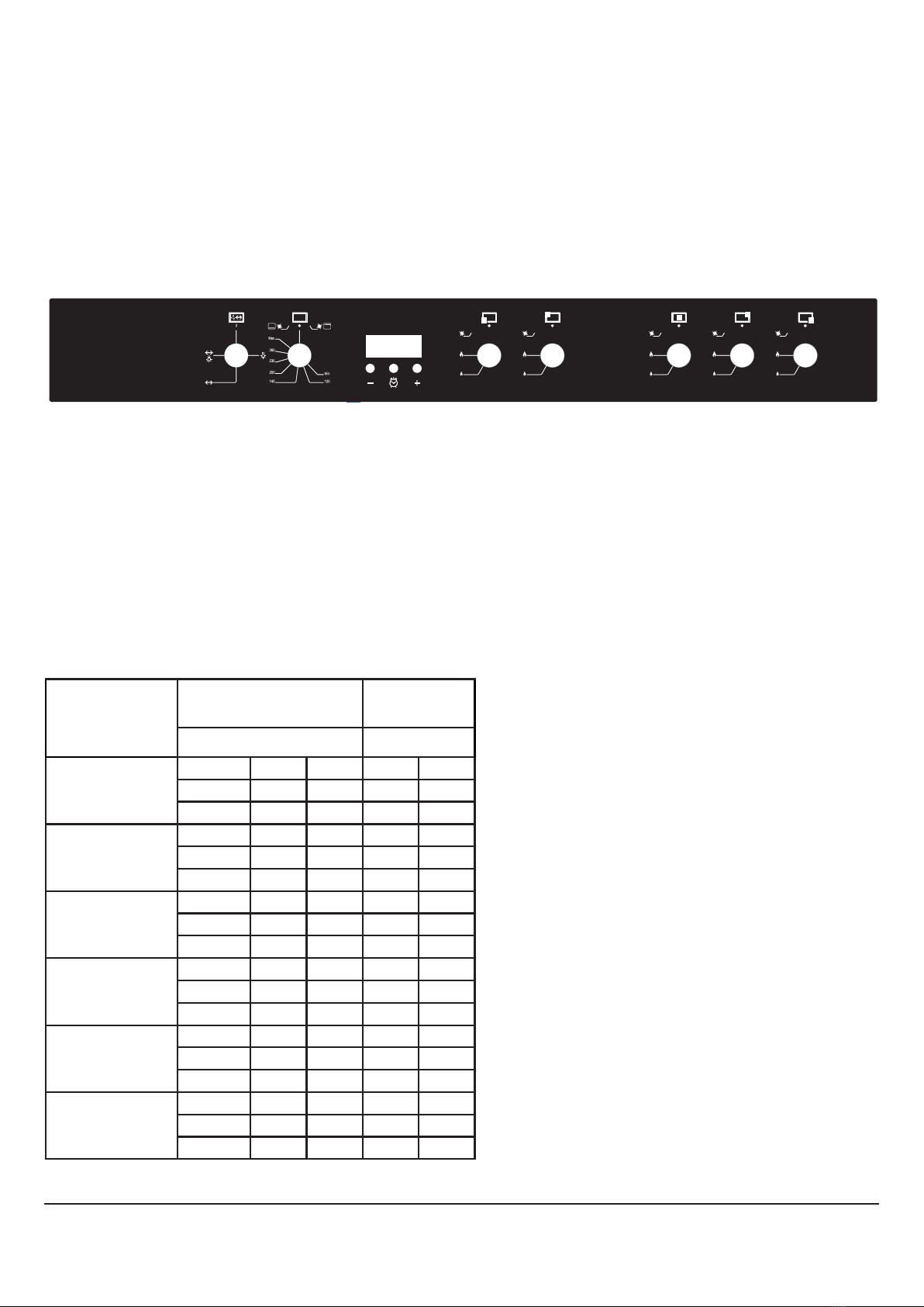
14
1. Lamp
2. Oven Temperature Controls
3. Display Screen
4. Front Left burner
5. Rear Left burner
6. Central burner
7. Rear Right burner
8. Front Right burner
WARNING: The control panel above is only for illustration purposes.
Consider the control panel on your device.
BURNER SPECIFICATIONS
YOUR RANGE COOKER (CONT.)
1 2 3 4 5 6 7 8
INSTALLATION OF YOUR OVEN
Burner
Specifications
G20,20 mbar
G25,25 mbar
G30,28-30 mbar
G31,37 mbar
Gas natural
LPG
Wok
Burner (3,5)
Injector
1,40
mm
0,96
mm
Gas flow
0,333
m³/h
254
g/h
Power
3,50
kW
3,50
kW
Rapid
Burner
Injector
1,15
mm
0,85
mm
Gas flow
0,276
m³/h
211
g/h
Power
2,90
kW
2,90
kW
Semi-Rapid
Burner
Injector
0,97
mm
0,65
mm
Gas flow
0,162
m³/h
124
g/h
Power
1,70
kW
1,70
kW
Auxiliary
Burner
Injector
0,72
mm
0,50
mm
Gas flow
0,96
m³/h
69
g/h
Power
0,95
kW
0,95
kW
Grill
Burner
Injector
1,10
mm
0,78
mm
Gas flow
0,238
m³/h
182
g/h
Power
2,50
kW
2,50
kW
Oven
Burner
Injector
1,30
mm
0,92
mm
Gas flow
0,333
m³/h
254
g/h
Power
3,50
kW
3,50
kW

15
INSTALLATION INSTRUCTIONS
INSTALLATION OF YOUR OVEN
Check if the electrical installation is proper to bring
the appliance in operating condition. If electricity
installation is not suitable, call an electrician and
plumber to arrange the utilities as necessary.
Manufacturer shall not be held responsible for
damages caused by operations performed by
unauthorized persons.
WARNING: It is customer's responsibility to prepare
the location the product shall be placed on and also
to have the electrical installation prepared.
WARNING: The rules in local standards about
electrical installations shall be followed during
product installation.
WARNING: Check for any damage on the appliance
before installing it.
Do not have the product installed if it is damaged.
Damaged products cause a risk for your safety.
RIGHT PLACE FOR INSTALLATION AND
IMPORTANT WARNINGS
Appliance feet should not stay on soft surfaces
such as carpets. The kitchen floor shall be durable
to carry the unit weight and any other kitchenware
that may be used on the oven.
The appliance is suitable for use on both side walls,
without any support, or without being installed in
a cabinet. If a hood or aspirator will be installed
above the cooker, follow the instructions of the
manufacturer for height of mounting. (min. 650
mm)
WARNING: The kitchen furniture near the appliance
must be heat resistant.
WARNING: Do not use the door and/or handle to
carry or move the appliance.
WARNING: Do not install the appliance beside
refrigerators or coolers.
Heat radiated by the appliance increases the energy
consumption of cooling devices.
28
WARNING: The kitchen furniture near the appliance must be heat
resistant.
WARNING: Do not use the door and/or handle to carry or move the appliance.
WARNING: Do not install the appliance beside refrigerators or coolers.
Heat radiated by the appliance increases the energy consumption of cooling
devices.
650mm min.
65 mm min. 65 mm min.

16
INSTALLATION OF THE OVEN FEET
Follow these instructions to install the oven feet;
1. Foot attachment lath is installed on the oven from the bottom of the oven as shown in (figure 10). Nuts
are centered on these lathes in order to screw feet. Complete the feet installation process by screwing
the feet to the nuts (figure 11).
2. You can balance your oven by turning the screwed feet according to the surface type you are using.
3. If your oven has plastic food as in (figure 12) you can adjust your ovens height from these feet as
turned clockwise or anticlockwise.
CHAIN LASHING
Before using the appliance, in order to ensure safe use, be sure to fix the appliance to the wall using
thechain and hooked screw supplied. Ensure that the hook is screwed into the wall securely.
INSTALLATION INSTRUCTIONS (CONT.)
29
Installation Of The Oven Feet
In order to install the oven feet;
1. Foot attachment lath is installed on the oven from the bottom of the
oven as shown in (gure 10).Nuts are centered on these lathes in order
to screw feet. Complete the feet installation process by screwing the feet
to the nuts (gure 11).
2. You can balance your oven by turning the screwed feet according to
the surface type you are using.
3. If your oven has plastic food as in (gure 12) you can adjust your
ovens height from these feet as turned clockwise or anticlockwise.
Chain Lashing Illustration
Before using the appliance, in order
to ensure safe use, be sure to fix the
appliance to the wall using thechain and
hooked screw supplied. Ensure that the
hook is screwed into the wall securely.
Figure 10 Figure 12Figure 11

17
INSTALLING THE OVEN DOOR
In order to re-place the oven door, perform the above steps in reverse
INSTALLATION INSTRUCTIONS (CONT.)
38
Installation Of The Oven Door
Figure 19 Figure 20
Completely open
the oven door by
pulling it to your-
self. Afterwards,
perform the un-
locking process by
pulling the hinge
lock upwards with
the help of a screw
driver as shown in
gure 19.1.
Bring the hinge
lock to the widest
angle as shown in
gure 19.2. Bring
both hinges con-
necting the oven
door to the oven to
the same position.
Afterwards, close
the oven door as to
lean on the hinge
lock as shown in
gure 20.1.
In order to re-place the oven door, perform the abovementioned steps in reverse.
To remove the
oven door, pull it
upwards by holding
it with both hands
when close to the
closed position as
shown in
gure 20.2.
Figure 19.1 Figure 19.2 Figure 20.1 Figure 20.2

18
OPERATION INSTRUCTIONS
TIME OF DAY ADJUSTMENT
Press to the “clock” button. The “•” icon between the hours and minutes will start to flash.
Using the “–” and “+” buttons, you can adjust the current time of day. Long presses of those buttons will
enable fast adjustments.
Pressing the “clock” button for a long time, until the hour and “•” between the hours and minutes start to
flash; will enable you to adjust just the hours portion of the display.
MINUTE MINDER ADJUSTMENT
Press to the “+” button. The screen will return to displaying the ‘0.00’ and the bell symbol will start to flash.
You can adjust the minute minder using the “+” and “–” buttons. After 6 seconds following the adjustment,
the bell symbol will be stabilized. The minute minder will start to countdown.
The minute minder time increments are in 10 seconds up to 99 minutes 50 seconds, thereafter the display
will show 1 hour and 40 minutes and the adjustment will be in 1 minute steps up to the 10 hours.
Note: In order to cancel a minute minder program, set the minute minder time down to 0.00 or press to
the “–” and +” buttons together.
CANCELLING THE BUZZER SOUND
When countdown of the minute minder is completed, the screen will return to displaying the current time
of day. The bell symbol will start to flash; a buzzer alarm is heard and will sound, if not stopped, for 7
minutes. Press any button to cancel the sound.
BUZZER TONE ADJUSTMENT
You may adjust the buzzer tone of the timer in the following way:
1. Pressing the “–” button, you can hear the currently set tone.
2. Releasing “–” and then pressing again, you can hear the next available (total 3) tone.
3. The last sound heard will be your adjusted one.
Note: After prolonged blackouts all functions will default to their factory settings and require
reprogramming.

19
OPERATION INSTRUCTIONS (CONT.)
35
PROGRAM TYPES
WARNING: All heater types and program types consisting of these heaters
may not be available at all models.
Roast chicken Fan
Lower and upper heating
elements Turbo heating and fan
Lamp Lower-upper heating element
and fan
Lower heating element and fan Grill and fan
Grill and roast chicken Grill
Grill and lamp Upper heating element
Electrical timer Lower heating element
Flame Ignition lighter
Small grill and fan Small grill
Function Button: Used for determining the heaters
to
be used for cooking the dish to be cooked in the
oven. Heater program types in this button and their
functions are described below. All heater types and
program types consisting of these heaters may not
be available at all models.
FUNCTION BUTTON
Used for determining the heaters to be used for cooking the dish to be cooked in the oven. Heater
program types in this button and their functions are described below. All heater types and program types
consisting of these heaters may not be available at all models.

20
OPERATION INSTRUCTIONS (CONT.)
USING OVEN BURNERS
1. If your oven equipped with burners that
operates with gas, appropriate knob should
be used in order to ignite the burners. Some
models have automatic ignition from the knob;
it is easy to ignite the burner by turning the
knob. Also, burners can be ignited by pressing
the ignition button or they can be ignited with a
match.
2. Do not continuously operate the igniter for
more than 15 seconds. If the burner does not
ignite, wait minimum one minute before trying
again. If the burner is extinguished for of the
any reason, close the gas control valve and wait
a minimum of one minute before trying again.
USING OVEN HEATING ELEMENTS
1. When your oven is operated first time, an
odour will be spread out which IS from using
the heating elements. In order to get rid of this,
operate it at 250 °C for 45-60 minutes while it is
empty.
2. Position the oven control knob to the desired
temperature to begin operation.
3. Kinds of meals, cooking times and thermostat
positions are given in cooking table. The values
given in the cooking table are characteristic
values and were obtained as a result of the
tests performed in our laboratory. You can
find different flavours suitable for your taste
depending on your cooking and using habits.
4. You can make chicken revolving in your oven by
means of the accessories.
5. Cooking times: The results may change
according to the area voltage and material
having different quality, amount and
temperatures.
6. During the time when cooking is being
performed in the oven, the oven door should
not be opened frequently. Otherwise circulation
of the heat may be imbalanced and the results
may change.
USING THE GRILL
1. When you place the grill on the top rack, the
food on the grill shall not touch the grill.
2. You can preheat for 5 minutes while grilling. If
necessary, you may turn the food upside down.
3. Food shall be in the center of the grill to provide
maximum air flow through the oven.
To turn on the grill;
1. Place the function button over the grill symbol.
2. Then, set it to the desired grill temperature.
To turn the grill off;
1. Set the function button to the off position.
WARNING: Keep the oven door closed while grilling.
(electrica grill)
WARNING: Keep the oven door closed while grilling.
(gas grill)
USING THE CHICKEN ROASTING
Place the spit on the frame. Slide turn spit frame
into the oven at the desired level. Locate a dripping
pan through the bottom in order to collect the fast.
Add some water in dripping pan for easy cleaning.
Do not forget to remove plastic part from spit. After
grilling, screw the plastic handle to the skewer
Figure 13 and take out the food from oven.
32
Using The Grill
1. When you place the grill on the top rack, the food on the grill shall
not touch the grill.
2. You can preheat for 5 minutes while grilling. If necessary, you may
turn the food upside down.
3. Food shall be in the center of the grill to provide maximum air ow
through the oven.
To turn on the grill;
1. Place the function button over the grill symbol.
2. Then, set it to the desired grill temperature.
To turn the grill off;
Set the function button to the off position.
WARNING: Keep the oven door closed while grilling. (electrical grill)
WARNING: Keep the oven door opened while grilling. (gas grill)
Using The Chicken Roasting *
Place the spit on the frame. Slide turn
spit frame into the oven at the desired
level.Locate a dripping pan through
the bottom in order to collect the fast.
Add some water in dripping pan for
easy cleaning.Do not forget to remove
plastic part from spit.After grilling,
screw the plastik handle to the skewer
and take out the food from oven.
Figure 13
Table of contents
Other TEKNIX Cooker manuals


Popular Cooker manuals by other brands

Cannon
Cannon HENLEY 10582G Use and Installation Instructions

Gorenje
Gorenje E52103AW instruction manual

Denali
Denali D-T2688L instruction manual

AEG
AEG COMPETENCE 318 V operating instructions

Parkinson Cowan
Parkinson Cowan Renown RG50MG Operating and installation instructions

Zanussi
Zanussi ZCM 611 Instruction booklet

DeLonghi
DeLonghi DEMX 9642 B manual

DeLonghi
DeLonghi DTR 906-DF Series Instruction on mounting and use

Parkinson Cowan
Parkinson Cowan Sonata SN55TCBUL Owners handbook and installation instructions

Smeg
Smeg CE9CMXA instructions

Euromaid
Euromaid EFS54FC-SGB user manual

Whirlpool
Whirlpool RJE-3750 Use and care guide


