Astra-941
Laser Tester
Operating Manual
The operating manual describes the operating principle, opera-
tional, storage and maintenance conditions pertaining to laser
tester Astra-941 (hereinafter “tester”) (Fig. 1).
1 Function
1.1 The tester is intended for remote operabil-
ity inspections of optic-electronic fire smoke
detectors Astra-421 (hereinafter Astra-421
detector).
1.2 The tester is powered by batteries (2 pcs.)
of СR2430 type (voltage –3.0 V).
Note –It is possible to use more common
batteries of СR2032 type. However, it will re-
duce the service life of such batteries.
1.3 The tester is protected against reversing
the polarity of the batteries.
2 Specifications
Coverage range, m, max............................................................10
Output emission power, mWt, max...............................................5
Power supply voltage, V...............................................................3
Current consumption during transmission, mA, max..................20
Emission wavelength, nm......................................from 630 to 680
Overall dimensions, mm, max....................................76 41 16
Weight, kg, max.......................................................................0.04
Operating conditions:
Temperature range, °С......................................from -10 up to +55
Relative air humidity, %.....................................up to 93 at +40 ºС
no moisture condensation
3 Delivery Set
Laser tester Astra-941..........................................................1 pcs.
Operating manual...............................................................1 copy.
4 Structure
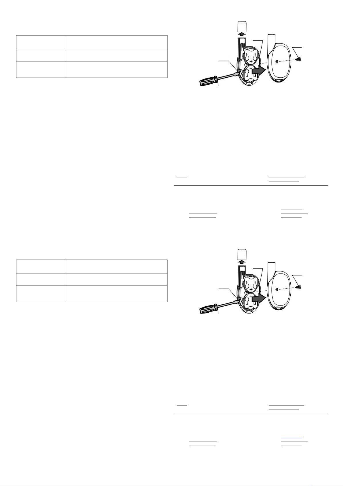
Structurally, the tester is designed as a key fob consisting of a
cover (face side) and a base (Fig.2).
Fig. 2
Mounted on the cover are a button and a printed circuit board
with radio elements and batteries. The cover is attached to the
base with a screw.
Mounted on PCB is an indicator which provides for tester operabili-
ty supervision.
Astra-941
Laser Tester
Operating Manual
The operating manual describes the operating principle, opera-
tional, storage and maintenance conditions pertaining to laser
tester Astra-941 (hereinafter “tester”) (Fig. 1).
1 Function
1.1 The tester is intended for remote operabil-
ity inspections of optic-electronic fire smoke
detectors Astra-421 (hereinafter Astra-421
detector).
1.2 The tester is powered by batteries (2 pcs.)
of СR2430 type (voltage –3.0 V).
Note –It is possible to use more common
batteries of СR2032 type. However, it will re-
duce the service life of such batteries.
1.3 The tester is protected against reversing
the polarity of the batteries.
2 Specifications
Coverage range, m, max............................................................10
Output emission power, mWt, max...............................................5
Power supply voltage, V...............................................................3
Current consumption during transmission, mA, max..................20
Emission wavelength, nm..............................................630 to 680
Overall dimensions, mm, max....................................76 41 16
Weight, kg, max.......................................................................0.04
Operating conditions:
Temperature range, °С......................................from -10 up to +55
Relative air humidity, %.....................................up to 93 at +40 ºС
no moisture condensation
3 Delivery Set
Laser tester Astra-941..........................................................1 pcs.
Operating manual...............................................................1 copy.
4 Structure
Structurally, the tester is designed as a key fob consisting of a
cover (face side) and a base (Fig.2).
Fig. 2
Mounted on the cover are a button and a printed circuit board
with radio elements and batteries. The cover is attached to the
base with a screw.
Mounted on PCB is an indicator which provides for tester operabili-
ty supervision.