STEINEL Combi Check 1.2 User manual

Spannungsprüfer
Combi Check 1.2
Master Check 3.2
D
GB
F
NL
I
E
S
FIN
DK
N
Bedienungsanleitung
Operating instructions
Mode d’emploi
Gebruiksaanwijzing
Istruzioni per l’uso
Instrucciones de manejo
Bruksanvisning
Brugsanvisning
Käyttöohje
Bruksanvisning

9
1
2
3
8
4
7
6
5
3
Combi Check 1.2
Master Check 3.2
Sicherheitshinweise
ç
y
Der Spannungsprüfer darf
nur innerhalb des angege-
benen Nennspannungs-
bereiches benutzt werden.
Die in DIN VDE 0105 Teil
100 und EN 50110-1 ent-
haltenen Anwendungs-
bestimmungen für Span-
nungsprüfer sehen vor,
dass kurz vor der Prüfung
auf Spannungsfreiheit, der
Spannungsprüfer auf
Funktion geprüft werden
muss. Fällt hierbei die
Anzeige aus, darf der
Spannungsprüfer nicht
mehr verwendet werden.
y
Die Anzeige der Über-
schreitung des oberen
Grenzwertes für Klein-
spannungen (ELV) dient
nur als Warnung für den
Benutzer und nicht als
Messwert.
y
Aufgrund des hohen Ein-
gangswiderstandes kann
eine Anzeige kapazitiver
und induktiver Spannun-
gen erfolgen.
y
Beim Prüfen nur an den
Griffen anfassen und die
Prüfelektroden nicht
berühren: Spannungs-
prüfung ausschließlich
2-polig durchführen.
y
An Einsatzorten mit hohem
Störgeräuschpegel muss
vor Gebrauch des Span-
nungsprüfers festgestellt
werden, ob das akustische
Prüfsignal wahrnehmbar
ist.
y
Die Anzeige der Leucht-
dioden erfolgt bei 80–85 %
der Stufenspannung.
y
Eine einwandfreie Anzeige
ist nur im Temperatur-
bereich von – 10 °C bis
+ 55 °C sichergestellt.
y
Die Funktion des Span-
nungsprüfers muss kurz
vor und nach der Prüfung
auf Spannungsfreiheit
geprüft werden. Fällt hier-
bei die Anzeige einer oder
mehrerer Stufen aus oder
wird keine Funktionsbereit-
schaft angezeigt, darf der
Spannungsprüfer nicht
weiter verwendet werden.
y
Unbefugte dürfen den
Spannungsprüfer und
dessen Ergänzungsein-
richtungen nicht zerlegen.
y
Die Aufbewahrung des
Gerätes sollte trocken und
in sauberer Umgebung
erfolgen.
y
Das Gerät darf unter Ein-
wirkung von Niederschlä-
gen (z. B. Tau oder Regen)
nicht verwendet werden
(IP 50).
y
Das Gerät kann im Rah-
men seiner höchstmög-
lichen Einschaltdauer (ED)
bis zu 30 Sekunden an die
höchste Nennspannung
des Nennspannungs-
bereiches angelegt wer-
den.
y
Die Wahrnehmbarkeit der
Anzeige kann bei ungüns-
tigen Beleuchtungs-
verhältnissen, z. B. bei
Sonnenlicht, beeinträchtigt
sein.
y
ACHTUNG:
Spannungsprüfer darf bei
geöffnetem Batteriefach
nicht benutzt werden.
D
2

Technische Daten
Batterie- und Funktionstest
Abmessungen: (L x B x H) 230 x 55 x 34 mm
Nennspannungs- Combi Check 1.2: 6–690 V AC/DC
bereich: Master Check 3.2: 6–400 V AC/DC
Frequenzbereich: 0–100 Hz;
Anzeige von AC bei f > 2 Hz
Spitzenspannungs- Combi Check 1.2: 6 KV
festigkeit: Master Check 3.2: 4 KV
Eingangswiderstand: > 300 kOhm
Eingangsstrom: Combi Check 1.2: Is < 2,5 mA bei 690 V
Master Check 3.2: Is < 2,5 mA bei 400 V
Durchgangsprüfung: Durchgang < 500 kOhm
Einpolige (nur Combi Check 1.2)
Phasenprüfung: Anzeige bei Spannungen
> 90 V AC (akustisches Signal)
Temperaturbereich: –10 °C bis +55 °C
Batterielebensdauer: ca. 1500 Prüfungen
Batterietyp: 2 x Micro 1,5 V AAA Alkaline
(keine Akkus verwenden)
Schutzklasse: IP 50
Zulassung: nach EN 61243-3
= VDE 0682 Teil 401
Gewicht: 135 g
Einlegen der Batterie:
Öffnen Sie das Batteriefach
mit Hilfe eines Schrauben-
drehers oder einer Münze.
Wenn die Rückseite des
Gerätes nach oben zeigt, und
der Riegel um 45° nach
rechts gedreht wird, löst sich
die Verriegelung, und der
Batteriekasten lässt sich bis
zum Anschlag herausziehen.
Batterien wie im Batterie-
kasten dargestellt einlegen
(keine Akkus verwenden!).
Zum Schließen des Batterie-
faches den Batteriekasten bis
zum Anschlag in das Ge-
häuse drücken und das Fach
durch eine Drehung des
Knebels um 45° nach links
einrasten.
ACHTUNG: Spannungsprüfer
darf bei geöffnetem Batterie-
fach nicht benutzt werden.
Funktionstest/Batterietest
Bei kurzgeschlossenen Prüf-
spitzen und gedrückter Taste
muss anfangs die gesamte
LED-Kette kurz aufleuchten.
Anschließend bleibt nur die
+6 V-Stufenanzeige an.
Zusätzlich ertönt ein akusti-
sches Signal. Blinkt bei
diesem Test die +6 V-Stufen-
anzeige, so müssen zum
nächstmöglichen Zeitpunkt
die Batterien gewechselt
werden.
Der notwendige Batterie-
wechsel wird zusätzlich
durch das Blinken der LED-
Kette bei Durchführung jeder
weiteren Spannungs-/Durch-
gangsprüfung angezeigt.
5
Combi Check 1.2
햲Prüfspitzenschutz
햳Prüfspitzen
햴Spannungsindikator, LED
햵Taster
햶Rastverbindung
햷Leuchtdioden für die
Anzeige von
쎻
aGleich- und
Wechselspannung
쎻bPolaritätsanzeige
쎻
cDurchgangsprüfung
쎻dPhasenprüfung
(nur Combi Check 1.2)
햸Batteriefach
햹Akustische Anzeige,
Buzzer
(nur Combi Check 1.2)
햺Prüfspitzenbeleuchtung
(nur Combi Check 1.2)
Master Check 3.2
햲Prüfspitzenschutz
햳Prüfspitzen
햴Spannungsindikator, LED
햵Taster
햶Rastverbindung
햷Leuchtdioden für die
Anzeige von
쎻
aGleich- und
Wechselspannung
쎻bPolaritätsanzeige
쎻
cDurchgangsprüfung
햸Batteriefach
Sehr geehrter Kunde,
vielen Dank für das Vertrauen,
das Sie uns beim Kauf Ihres
neuen STEINEL Spannungs-
prüfers entgegengebracht
haben. Sie haben sich für ein
hochwertiges Qualitäts-
produkt entschieden, das mit
größter Sorgfalt produziert,
getestet und verpackt wurde.
Der Stufenspannungsprüfer
bietet Ihnen folgende
Funktionen:
– Anzeige von Gleich- und
Wechselspannung
– Polaritätsanzeige
– Durchgangsprüfung mit
Taster
– Erkennung von Span-
nungen > 50 V AC/
120 V DC auch ohne
Batterien
– Automatische
Batterieüberwachung
– Ein-Hand-Bedienung bei
Steckdosenprüfung durch
Rastverbindung der Prüf-
spitzen
– Phasenprüfung
(nur Combi Check 1.2)
– Optische und akustische
Anzeige
(nur Combi Check 1.2)
– Zuschaltbare
Prüfspitzenbeleuchtung
(nur Combi Check 1.2)
Gerätebeschreibung
Bedienungsanleitung
D
4

Phasenprüfung
(nur Combi Check 1.2)
ACHTUNG: Bei ungünstigen
Standorten, z. B. auf Holztritt-
leitern oder isolierenden Fuß-
bodenbelägen und in nicht
betriebsgemäß geerdeten
Wechselspannungsnetzen,
kann die Phasenprüfung
nicht durchgeführt werden.
y
Zur Durchführung der
Phasenprüfung die kleine
Prüfspitze mit der Phase
(> 90 V AC) des Wechsel-
spannungsnetzes kontak-
tieren und den Phasen-
prüferkontakt am Anzeige-
griff mit dem Daumen
kontaktieren. Bei Phasen-
kontakt leuchtet die
6 V-Stufenanzeige
(+ und –) auf und zusätz-
lich ertönt ein akustisches
Signal.
7
Halbleiterprüfung
Für die polaritätsabhängige
Durchgangsprüfung (Halb-
leiterprüfung) wird bei Betäti-
gung des Tasters die interne
Prüfspannungsquelle auf die
Prüfspitzen geschaltet.
Hierbei stellt der Anzeigegriff
den Pluspol und der kleine
Griff den Minuspol dar. Bei
Durchgang leuchtet die
+6 V-Diode auf. Beim Combi
Check 1.2 ertönt zusätzlich
ein akustisches Signal.
Spannungsprüfung
햲Tastspitzen an zu prüfende
Potentialpunkte anlegen.
y
Für die Gleichspannungs-
prüfung stellt die Prüfspitze
des Anzeigegriffes den Plus-
pol und die kleine Prüf-
spitze den Minuspol dar.
y
Bei Wechselspannung
leuchten die Plus- und
die Minus-Diode der 6 V-
Spannungsstufe gleich-
zeitig auf.
y
Zu Beginn jeder Span-
nungsprüfung leuchtet die
gesamte LED-Kette einmal
kurz auf.
햳Die Höhe der anliegenden
Spannung wird durch das
Aufleuchten der Leucht-
dioden bis zum Stufen-
wert der anliegenden
Spannung angezeigt.
Beim Combi Check 1.2
ertönt zusätzlich ein
akustisches Signal.
Durchgangsprüfung
햲Vor Durchführung einer
Durchgangsprüfung in
Anlagen sind Fremdspan-
nungen abzuschalten und
gegebenenfalls Konden-
satoren zu entladen.
햳Prüfspitzen kurzschließen
und Taste gedrückt halten.
햴Prüfling mit den Prüf-
spitzen kontaktieren. Bei
einem Durchgangswider-
stand < 500 kOhm leuch-
tet die +6 V-Diode auf.
Beim Combi Check 1.2
ertönt zusätzlich ein
akustisches Signal.
Anliegende Fremdspannun-
gen werden trotz Durch-
gangsprüfung angezeigt und
führen zu keiner Zerstörung
des Gerätes.
6

CKonformitätserklärung
Das Produkt erfüllt die
Niederspannungsrichtlinie 73/23/EWG und die EMV-
Richtlinie 89/336/EWG.
Funktionsgarantie
Dieses STEINEL-Produkt ist
mit größter Sorgfalt hergestellt,
funktions- und sicherheitsge-
prüft nach geltenden Vor-
schriften und anschließend
einer Stichprobenkontrolle
unterzogen.
Die Garantiefrist beträgt
36 Monate und beginnt mit
dem Tag des Verkaufs an den
Verbraucher. Wir beseitigen
Mängel, die auf Material- oder
Fabrikationsfehlern beruhen,
die Garantieleistung erfolgt
durch Instandsetzung oder
Austausch mangelhafter Teile
nach unserer Wahl.
Eine Garantieleistung entfällt
für Schäden an Verschleiß-
teilen, für Schäden und Män-
gel, die durch unsachgemäße
Behandlung oder Wartung
auftreten sowie für Bruch bei
Sturz.
Weitergehende Folgeschäden
an fremden Gegenständen
sind ausgeschlossen. Die
Garantie wird nur gewährt,
wenn das unzerlegte Gerät mit
Kassenbon oder Rechnung
(Kaufdatum und Händler-
stempel), gut verpackt, an die
zutreffende Servicestation ein-
gesandt oder in den ersten
6 Monaten dem Händler über-
geben wird.
Reparaturservice:
Nach Ablauf der Garantiezeit
oder Mängeln ohne Garantie-
anspruch repariert unser
Werkservice. Bitte das
Produkt gut verpackt an die
nächste Servicestation
senden.
8
Zuschaltbare Prüfspitzenbeleuchtung
(nur Combi Check 1.2)
Die Prüfspitzenbeleuchtung
kann manuell durch Drücken
der Taste und einmaliges
Kurzschließen der Prüfspitzen
eingeschaltet werden. Die
Beleuchtung bleibt nur für
die Dauer der Tastenbetäti-
gung eingeschaltet.
Combi Check 1.2
햲Test probe guard
햳Test probes
햴Voltage indicator, LED
햵Pushbutton
햶Clip connector
햷LED's for indicating
쎻
aDC and AC voltage
쎻bpolarity
쎻
ccontinuity testing
쎻dphase testing
(Combi Check 1.2
only)
햸Battery compartment
햹Accoustic indicator, buz-
zer (Combi Check 1.2
only)
햺Test probe light
(Combi Check 1.2 only)
Master Check 3.2
햲Test probe guard
햳Test probes
햴Voltage indicator, LED
햵Pushbutton
햶Clip connector
햷LED's for indicating
쎻
aDC and AC voltage
쎻bpolarity
쎻
ccontinuity testing
햸Battery compartment
Dear Customer
Congratulations on purchas-
ing your new STEINEL
Voltage Tester and thank you
for the confidence you have
shown in us. You have cho-
sen a high-quality product
that has been manufactured,
tested and packed with the
greatest care. The step volt-
age tester is capable of the
following functions:
– DC and AC voltage indica-
tion
– Polarity indication
– Continuity testing with
pushbutton
– Voltage detection > 50 V
AC / 120 V DC even with-
out batteries
– Automatic battery monitor-
ing
– Single-hand operation for
testing socket outlets using
clip connector for test pro-
bes
– Phase testing
(Combi Check 1.2 only)
– Visual and accoustic
indicator (Combi Check 1.2
only)
– Selectable test probe light
(Combi Check 1.2 only)
Description
Instructions for Use
GB
9

Technical Specifications
Battery and Function Test
Dimensions: (L x W x H) 230 x 55 x 34 mm
Rated voltage range: Combi Check 1.2: 6–690 V AC/DC
Master Check 3.2: 6–400 V AC/DC
Frequency range: 0–100 Hz;
AC display from f > 2 Hz
Voltage surge proof: Combi Check 1.2: 6 KV
Master Check 3.2: 4 KV
Input resistance: > 300 kOhm
Input current: Combi Check 1.2: Is < 2.5 mA at 690 V
Master Check 3.2: Is < 2.5 mA at 400 V
Continuity testing: Continuity < 500 kOhm
Single-pole phase testing:
Continuity at voltages
(Combi Check 1.2 only)
> 90 V AC (acoustic signal)
Temperature range: – 10 °C to + 55 °C
Battery life: approx. 1500 operations
Battery type: 2 x micro 1.5 V AAA Alkaline
(do not use rechargeable batteries)
Enclosure: IP 50
Approval: to EN 61243-3
= VDE 0682 Part 401
Weight: 135 g
Battery installation:
Open the battery compart-
ment using a screwdriver or
a coin. With the rear side of
the unit facing up, turn the
catch clockwise through 45°
to unlock. Now pull the bat-
tery compartment out as far
as the stop. Install batteries
as indicated (do not use
rechargeable batteries). To
close the battery compart-
ment, push the battery com-
partment as far as it will go
into the housing and lock the
compartment in place by
turning the catch anticlock-
wise through 45°.
WARNING: Voltage tester
must not be used with the
battery compartment open.
Function test/battery test
With the test probes shorted
and pushbutton pressed the
entire LED step display must
come on briefly, leaving only
the +6 V step indicator on.
An acoustic signal will also
sound. If the +6 V step indi-
cator flashes during this test,
change the batteries at the
next opportunity possible.
The LED step display will
flash while conducting further
voltage/continuity checks to
remind you that the batteries
need changing.
11
Safety Instructions
ç
y
The voltage tester must
only be used within the
specified rated voltage
range. The provisions con-
tained in DIN VDE 0105
Part 100 and EN 50110-1
regarding the use of volt-
age testers stipulate that
just before testing for iso-
lation from supply, the
voltage tester must be
checked for proper work-
ing order. If the indicator
fails to operate during this
check, the voltage tester
must not be used.
y
Indication that the upper
limit for extra-low voltages
(ELV) has been exceeded
only serves as a warning
to the user and not as a
measurement reading.
y
Due to the high input
resistance, the capacitive
and inductive voltages
may be indicated.
yWhen testing, hold the
voltage tester by its hand-
les only. Do not touch the
test electrodes. Only per-
form 2-pole voltage tests.
y
Before using the voltage
tester in places where
noise levels are high,
first check whether the
accoustic test signal is
audible.
y
The LEDs start to glow at
80-85 % of designated
voltage.
y
Reliable indication is only
assured over a tempera-
ture range of –10 °C to
+55 °C.
y
The voltage tester must be
checked for proper work-
ing order shortly before
and after testing for isola-
tion from supply. If this
check reveals any failure
of the tester to indicate
one or more steps or if the
voltage tester fails to show
that it is ready for opera-
tion, it must not be used.
y
The voltage tester and its
accessories must not be
dismantled by unauthor-
ized persons.
y
The tester must be stored
in a dry and clean place.
y
The tester must not be
used in wet conditions
(e.g. condensation or rain)
(IP 50).
y
Within its maximum ON
duration, the device may
be exposed for up to 30
seconds to the maximum
rated voltage of the indi-
cated range.
y
Indicator legibility may be
impaired in adverse light
conditions, e.g. in sunlight.
y
WARNING: Voltage tester
must not be used with the
battery compartment open.
GB
10

Phase testing
(Combi Check 1.2 only)
WARNING: Phase testing
cannot be performed in
unfavourable locations, e.g.
on ladders with wooden
rungs or in rooms with insu-
lated floor coverings and in
AC voltage systems not
properly bonded to earth.
y
To perform the phase test,
contact the small test
probe with the phase
(> 90 V AC) of the AC
voltage system and touch
the phase tester contact
on the indicator handle
with your thumb. The 6 V
step indicator (+ and –)
will light up upon phase
contact and an acoustic
signal is also given.
13
Semiconductor testing
When the button is pressed
during polarity-dependent
continuity testing, the internal
test voltage source is
switched to the test probes.
The display handle repre-
sents the positive pole, and
the small handle the negative
pole. If continuity is given, the
+6 V diode illuminates. An
acoustic indication is also
given for Combi Check 1.2.
incorrectcorrect
Voltage testing
햲Apply the test probes to
the potential points you
wish to test.
y
For DC voltage testing, the
test probe on the display
handle represents the
positive pole, and the
small test probe the neg-
ative pole.
y
The positive and the neg-
ative diode of the 6 V volt-
age step will light up
simultaneously for AC
voltage.
y
The entire LED step dis-
play will briefly light up at
the start of each voltage
test.
햳The level of voltage pre-
sent is indicated by the
LED's lighting up as far as
the step level of voltage
present. An acoustic indi-
cation is also given for
Combi Check 1.2.
Continuity testing
햲Before conducting a con-
tinuity test in electrical
systems, first switch off
external voltage sources
and, where applicable,
discharge capacitors.
햳Short the test probes and
keep button pressed.
햴Contact the test object
with the test probes.
Contact the test object
with the test probes. If
contact resistance is
< 500 kOhms, the +6 V
diode will light up.
An acoustic indication is also
given for Combi Check 1.2.
Impressed external voltages
will be indicated despite the
continuity test, and will not
harm the tester.
12

CDeclaration of Conformity
This product complies with
Low Voltage Directive 73/23/EEC and EMC
Directive 89/336/EEC.
Functional Warranty
This STEINEL product has
been manufactured with
great care, and its operation
and safety have been tested
in conformity with the current
regulations. Production is
also submitted to final ran-
dom-sample testing.
The warranty period is
36 months, starting on the
date of sale to the user. We
undertake to remedy faults
caused by material or manu-
facturing defects. This war-
ranty undertaking shall be
performed by the repair or
replacement of the defective
parts, at our own discretion.
This warranty shall not cover
damage to wearing parts or
damage and faults caused
by incorrect operation or
maintenance. Breakage due
to a fall is also not covered.
Further consequential dama-
ge to external items is ex-
cluded.
Claims under warranty shall
only be accepted if the pro-
duct is sent fully assembled
and well packed complete
with sales slip or invoice
(date of purchase and dea-
ler’s stamp) to the appro-
priate Service Centre or
handed in to the dealer
within the first 6 months.
Repair Service:
Our Customer Service
Department will repair faults
not covered by warranty or
after the warranty period.
Please send the product well
packed to your nearest
Service Centre.
14
Selectable test probe light
(Combi Check 1.2 only)
The test probe light can be
switched on manually by
pressing the button and
briefly shorting the test pro-
bes. The light only remains
on while the button is
pressed.
Combi Check 1.2
햲Protection des pointes de
test
햳Pointes de test
햴Témoin de tension, DEL
햵Poussoir
햶Cran
햷Diodes pour l’affichage
de:
쎻
atensions continues et
alternatives
쎻bpolarité
쎻
ctest de continuité
쎻dtest de phase (uni-
quement Combi
Check 1.2)
햸Compartiment à piles
햹Avertisseur sonore
pour signal acoustique
(uniquement Combi
Check 1.2)
햺Éclairage des pointes de
test (uniquement Combi
Check 1.2)
Master Check 3.2
햲Protection des pointes de
test
햳Pointes de test
햴Témoin de tension, DEL
햵Poussoir
햶Cran
햷Diodes pour l’affichage
de:
쎻
atensions continues et
alternatives
쎻bpolarité
쎻
ctest de continuité
햸Compartiment à piles
Cher client,
Nous vous remercions de la
confiance que vous avez
témoignée à STEINEL en
achetant ce testeur de ten-
sion. Vous avez choisi un
article de très grande qualité,
fabriqué, testé et conditionné
avec le plus grand soin. Le
testeur de tension vous offre
les fonctions suivantes:
– affichage de tensions con-
tinues et alternatives,
– affichage de la polarité,
– test de continuité avec
poussoir,
– détection de tensions
> 50 V C.A./ 120 V C.C.
même sans piles,
– contrôle automatique des
piles,
– utilisation d’une seule main
pour les tests de prises de
courant par enclenchement
des pointes de test,
– test de phase (uniquement
Combi Check 1.2),)
– affichage visuel et signal
acoustique (uniquement
Combi Check 1.2),
– éclairage débrayable des
pointes de test (unique-
ment Combi Check 1.2).
Description de l’appareil
Mode d’emploi
F
15

Caractéristiques techniques
Test des piles et du fonctionnement de l’appareil
Dimensions : (L x l x H) 230 x 55 x 34 mm
Plage de tension nominale : Combi Check 1.2 : 6-690 V C.A./C.C.
Master Check 3.2 : 6-400 V C.A./C.C.
Plage de fréquences : 0–100 Hz ;
affichage du C.A. pour f > 2 Hz
Résistance aux crêtes de tension :
Combi Check 1.2 : 6 KV
Master Check 3.2 : 4 KV
Résistance d’entrée : > 300 kOhm
Courant d’entrée : Combi Check 1.2 : Is < 2,5 mA pour 690 V
Master Check 3.2 : Is < 2,5 mA pour 400 V
Test de continuité : continuité < 500 kOhm
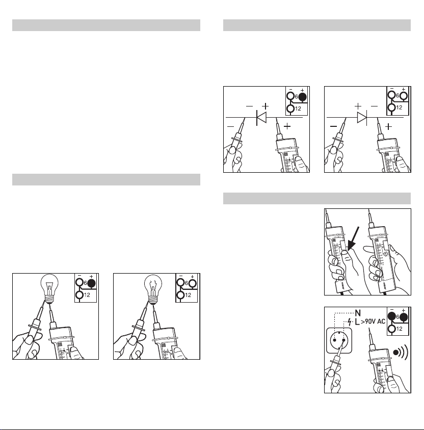
Test de phase unipolaire : affichage pour les tensions
(uniquement Combi Check 1.2)
> 90 V C.A. (signal acoustique)
Température d’utilisation : de –10 °C à +55 °C
Durée de vie des piles : env. 1 500 tests
Type de pile : 2 x Micro 1,5 V AAA alcalines
(ne pas utiliser de piles rechargeables)
Indice de protection : IP 50
Homologation : selon EN 61243-3
= VDE 0682 partie 401
Poids : 135 g
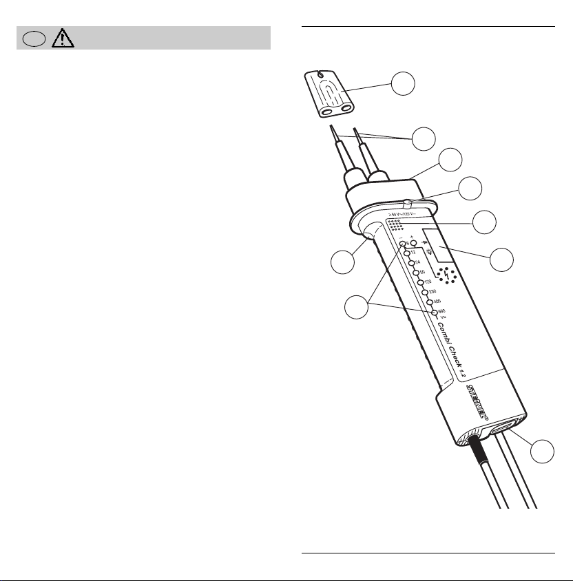
Mise en place des piles:
Ouvrir le compartiment à
piles avec un tournevis ou
une pièce de monnaie.
Quand la face arrière de
l’appareil est vers le haut et
qu’on tourne le verrou de 45°
vers la droite, la fermeture
s’ouvre et on peut retirer le
boîtier à piles jusqu’à la
butée. Mettre les piles en
place de la façon indiquée
dans le boîtier (ne pas utili-
ser de piles rechargeables!).
Pour fermer le compartiment
à piles, enfoncer le boîtier à
piles jusqu’à la butée dans le
compartiment et enclencher
le compartiment en faisant
tourner le verrou de 45° vers
la gauche.
ATTENTION: ne pas utiliser
le testeur de tension quand
le compartiment à piles est
ouvert.
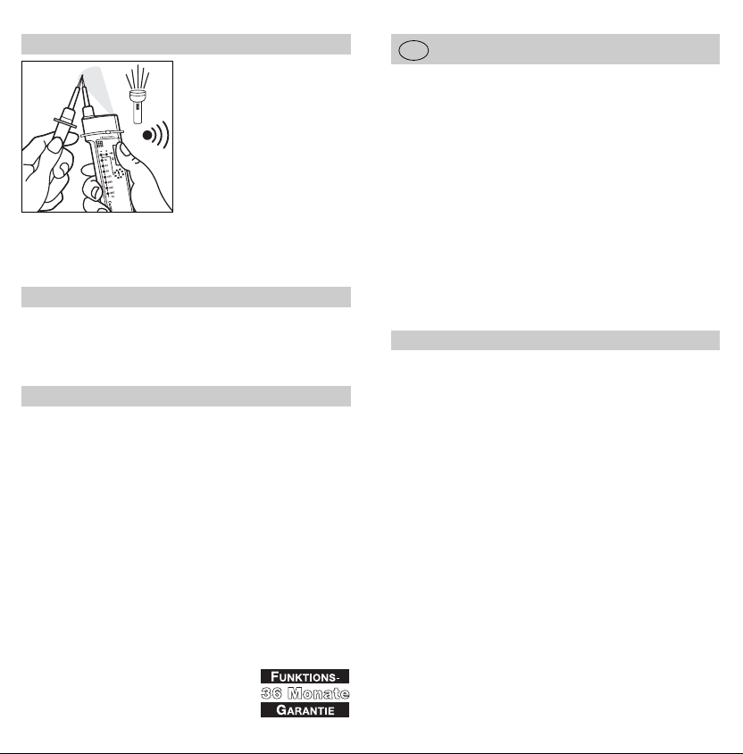
Test de fonctionnement/test
des piles:
Court-circuiter les pointes de
test et appuyer sur le bouton.
Toutes les DEL doivent s’allu-
mer pendant un bref instant.
Ensuite, seule la diode +6 V
reste allumée et l’appareil
émet un signal acoustique. Si
la diode +6 V clignote pen-
dant ce test, il faut changer
les piles le plus rapidement
possible.
À chaque test de
tension/continuité suivant, les
DEL clignotent pour rappeler
qu’il faut changer les piles.
17
Consignes de sécurité
ç
y
Le testeur de tension ne
doit être utilisé que dans la
plage de tension nominale
indiquée. Les dispositions
d’emploi relatives aux tes-
teurs de tension (norme
NF-C-18-510 Section
8.2.1) indiquent qu'il faut
vérifier le bon fonctionne-
ment du testeur juste avant
de procéder à l'essai d'ab-
sence de tension. En cas
de défaillance de l'afficha-
ge pendant cette vérificati-
on, il ne faut plus utiliser le
testeur de tension.
y
L’indication d’un dépasse-
ment de la limite supérieu-
re pour tensions faibles
(ELV) a pour unique but
d’avertir l’utilisateur et ne
constitue pas une valeur
de mesure.
y
Grâce à la résistance
d’entrée élevée, l’appareil
peut afficher des tensions
capacitives ou inductives.
y
Pendant le test, tenir l'ap-
pareil uniquement par les
poignées et ne pas tou-
cher les pointes de test.
N'effectuer que des tests
de tension bipolaires.
y
Avant d’utiliser le testeur
de tension dans un endroit
bruyant, il faut s’assurer
que le signal acoustique
est audible.
y
Les diodes s’allument à
80-85 % de la plage de
tension concernée.
yL'affichage correct n'est
garanti que dans une plage
de températures comprise
entre –10 °C et +55 °C.
y
Il faut vérifier le bon fonc-
tionnement du testeur
juste avant et après l'essai
d'absence de tension. Si
une ou plusieurs diodes
ne s’allument pas ou si le
témoin de disponibilité
reste éteint, il ne faut plus
utiliser le testeur.
y
Il est interdit à toute per-
sonne non autorisée de
démonter le testeur de
tension et ses dispositifs
complémentaires.
y
Il faut ranger l'appareil
dans un endroit sec et
propre.
y
Ne pas utiliser l'appareil
quand il est exposé aux
précipitations (p. ex. rosée
ou pluie) (IP 50).
y
Dans le cadre de son
fonctionnement prolongé
maximum, l'appareil peut
être raccordé jusqu'à
30 secondes à la tension
maximum de la plage de
tension nominale.
y
Un éclairage défavorable
(p. ex. soleil) peut affecter
la lisibilité de l'affichage.
y
ATTENTION: ne pas utili-
ser le testeur de tension
quand le compartiment à
piles est ouvert.
F
16

Test de phase
(uniquement
Combi Check 1.2)
ATTENTION: Il n’est pas
possible de procéder au test
de phase quand l’utilisateur
se tient à des endroits défa-
vorables, comme des esca-
beaux en bois ou des revête-
ments de sol isolants, ou
dans des réseaux de tension
alternative incorrectement
mis à la terre.
y
Pour procéder au test de
phase, mettre la petite
pointe de test en contact
avec la phase (> 90 V
C.A.) du réseau de tension
alternative et poser le
pouce sur le contact du
testeur de phase de la
poignée d’affichage. En
cas de contact de phase,
les diodes 6 V (+ et -) s’al-
lument et l’appareil émet
en plus un signal acous-
tique.
19
Test de semi-conducteur
Pour les tests de continuité
dépendant de la polarité
(test de semi-conducteur), la
source de tension interne est
connectée aux pointes de
test quand on actionne le
poussoir. La poignée d’affi-
chage est le pôle positif et
la petite poignée le pôle
négatif.
En cas de continuité, la
diode +6 V s’allume. Le
Combi Check 1.2 émet en
plus un signal acoustique.
correct incorrect
Test de tension
햲Mettre les pointes de test
en contact avec les points
de potentiel à tester.
y
Pour le test de tension
continue, la pointe de test
de la poignée d’affichage
est le pôle positif et la
petite pointe de test le
pôle négatif.
y
Dans le cas de tensions
alternatives, les diodes
positives et négatives 6 V
s’allument en même
temps.
y
Au début de chaque test
de tension, toutes les DEL
s’allument pendant un
bref instant.
햳La valeur de la tension
testée est indiquée par
l’allumage des diodes
jusqu’à la plage corres-
pondant à la tension
testée.
Le Combi Check 1.2
émet en plus un signal
acoustique.
Test de continuité
햲Avant d’effectuer un test
de continuité sur des
installations, il faut couper
les tensions d’origine
extérieure et, le cas
échéant, décharger les
condensateurs.
햳Court-circuiter les pointes
de test et maintenir le
bouton enfoncé.
햴Mettre le circuit à tester
en contact avec les poin-
tes de test. Si la résis-
tance transversale est
inférieure à 500 kΩ, la
diode +6 V s’allume.
Le Combi Check 1.2 émet en
plus un signal acoustique.
Malgré le test de continuité,
les tensions d’origine
extérieure peuvent être
affichées et ne détériorent
en aucun cas l’appareil.
18

CDéclaration de conformité CE
Ce produit répond aux pre-
scriptions de la directive
basse tension 73/23/CEE et
de la directive Compatibilité
électromagnétique
89/336/CEE.
Service après-vente et garantie
Ce produit STEINEL a été
fabriqué avec le plus grand
soin. Son fonctionnement et
sa sécurité ont été contrôlés
suivant des procédures fiables
et il a été soumis à un con-
trôle final par sondage.
La durée de garantie est de
36 mois et débute au jour de
la vente au consommateur.
Nous remédions aux défauts
provenant d'un vice de matiè-
re ou de construction. La
garantie sera assurée à notre
discrétion par réparation ou
échange des pièces défectu-
euses.
La garantie ne s'applique ni
aux pièces d'usure, ni aux
dommages et défauts dus à
une utilisation ou maintenance
incorrectes, ni aux bris de piè-
ces consécutifs à une chute.
Les dommages consécutifs
causés à d'autres objets sont
exclus de la garantie. La
garantie ne s'applique que si
l'appareil non démonté est
retourné à la station de servi-
ce après-vente la plus proche,
dans un emballage adéquat,
accompagné d'une facture ou
d'un ticket de caisse portant
la date d'achat et le cachet du
vendeur ou s'il est remis au
vendeur dans les 6 premiers
mois de la garantie.
Service de réparation:
Le service après-vente de
notre usine effectue égale-
ment les réparations non cou-
vertes par la garantie ou sur-
venant après l'expiration de
celle-ci. Veuillez envoyer le
produit correctement emballé
à la station de service après-
vente la plus proche.
20
Éclairage débrayable des pointes de test
(uniquement
Combi Check 1.2)
On allume l’éclairage des
pointes de test en appuyant
sur le bouton et en court-cir-
cuitant une fois les pointes
de test. L’éclairage ne reste
allumé que tant que le bou-
ton reste enfoncé.
Combi Check 1.2
햲Bescherming van de
testpennen
햳Testpennen
햴Spanningsindicator, LED
햵Druktoets
햶Arrêteerverbinding
햷Lichtdioden voor de
weergave van
쎻
aGelijk- en wisselspan-
ning
쎻bPolariteit
쎻
cDoorgangsmeting
쎻dFasemeting (alleen
Combi Check 1.2)
햸Batterijvakje
햹Akoestische weergave,
buzzer (alleen Combi
Check 1.2)
햺Verlichting testpennen
(alleen Combi Check 1.2)
Master Check 3.2
햲Bescherming van de
testpennen
햳Testpennen
햴Spanningsindicator, LED
햵Druktoets
햶Arrêteerverbinding
햷Lichtdioden voor de
weergave van
쎻
aGelijk- en wisselspan-
ning
쎻bPolariteit
쎻
cDoorgangsmeting
햸Batterijvakje
Geachte klant,
Hartelijk dank voor het ver-
trouwen dat u met de aan-
schaf van uw nieuwe span-
ningsmeter van STEINEL in
ons stelt. U heeft een hoog-
waardig kwaliteitsproduct
gekocht, dat met uiterste
zorgvuldigheid vervaardigd,
getest en verpakt werd. De
trapsgewijs werkende span-
ningsmeter biedt de volgen-
de functies:
- Weergave van gelijk- en
wisselspanning
- Polariteitsweergave
- Doorgangsmeting met
druktoets
- Herkenning van spannin-
gen > 50 V AC/120 V DC
ook zonder batterijen
- Automatische batterijcon-
trole
- Bediening met één hand bij
stopcontactcontrole door
arrêteerverbinding van de
testpennen
- Fasemeting (alleen Combi
Check 1.2)
- Optische en akoestische
weergave (alleen Combi
Check 1.2)
- Extra inschakelbare test-
penverlichting (alleen
Combi Check 1.2)
Beschrijving van het apparaat
Gebruiksaanwijzing
NL
21

Technische gegevens
Batterij- en functietest
Afmetingen: (l x b x h) 230 x 55 x 34 mm
Nominaal spanningsbereik:
Combi Check 1.2: 6-690 V AC/DC
Master Check 3.2: 6-400 V AC/DC
Frequentiebereik: 0–100 Hz;
weergave van AC bij f > 2 Hz
Diëlektrische topspanning:
Combi Check 1.2: 6 KV
Master Check 3.2: 4 KV
Ingangsweerstand: > 300 kOhm
Ingangsstroom: Combi Check 1.2: IS < 2,5 mA bij 690 V
Master Check 3.2: IS < 2,5 mA bij 400 V
Doorgangsmeting: doorgang < 500 kOhm
Eénpolige fasemeting: weergave bij spanningen
(alleen Combi Check 1.2)
> 90 V AC (akoestisch signaal)
Temperatuurbereik: –10 °C tot + 55 °C
Levensduur batterij: ca. 1500 metingen
Type batterij: 2 x micro 1,5 V AAA alkaline
(geen accu’s gebruiken)
Bescherming: IP 50
Toegestaan: volgens EN 61243-3
= VDE 0682, deel 401
Gewicht: 135 g
Plaatsen van de batterij:
Met behulp van een schroe-
vendraaier of een munt het
batterijvakje openen. Als het
apparaat met de achterzijde
naar boven ligt en de ver-
grendeling 45° naar rechts
wordt opengedraaid, kan het
batterijhuis tot de aanslag
naar buiten worden getrok-
ken. De batterijen zoals in het
batterijhuis aangegeven
plaatsen (geen accu’s
gebruiken!). Het batterijvakje
sluiten door het batterijhuis
tot aan de aanslag in het
vakje te schuiven. Vervolgens
het vakje inklikken door de
knevel 45° naar links te
draaien.
LET OP: Bij geopend batteri-
jvakje mag de spanningsme-
ter niet worden gebruikt.
Functietest/batterijtest
Bij kortgesloten testpennen
en ingedrukte knop moet aan
het begin de gehele LED-
keten kort oplichten.
Vervolgens blijft alleen de
weergave op +6 V-stand
staan. Bovendien klinkt een
akoestisch signaal. Knippert
bij deze test de +6 V-stand
weergave, dan dienen de
batterijen zo spoedig mogeli-
jk te worden vervangen.
De noodzakelijke batterijver-
vanging wordt bovendien
aangegeven door het knip-
peren van de LED-keten bij
het uitvoeren van elke vol-
gende spannings-/door-
gangsmeting.
23
Veiligheidsvoorschriften
ç
y
De spanningsmeter mag
alleen binnen het aange-
geven nominaalspannings-
bereik worden gebruikt. De
in DIN VDE 0105, deel 100
en EN 50110-1 vermelde
toepassingsbepalingen
voor spanningsmeters
schrijven voor, dat kort
voor het meten op span-
ningsloze staat, de span-
ningsmeter getest moet
worden op zijn functie. Valt
hierbij de weergave uit,
dan mag de spanningsme-
ter niet meer worden
gebruikt.
y
De weergave van over-
schrijding van de bovenste
grenswaarde voor lage
spanningen (ELV) dient
alleen als waarschuwing
voor de gebruiker en niet
als gemeten waarde.
y
Door de hoge ingangs-
weerstand kan een weer-
gave van capacitieve en
inductieve spanningen
plaatsvinden.
y
Bij het meten alleen bij de
grepen vasthouden en de
testelektroden niet aanra-
ken: spanningsmeting uit-
sluitend 2-polig uitvoeren.
y
Op plaatsen met intensieve
geluidsstoring moet voor
gebruik van de spannings-
meter worden vastgesteld
of het akoestische test-
signaal te horen is.
y
De lichtdioden geven de
spanning trapsgewijs bij
80-85 % aan.
y
Alleen binnen een tempe-
ratuurbereik van –10 °C
tot +55 °C is een correcte
weergave gewaarborgd.
y
De functie van de span-
ningsmeter moet kort voor
en na de meting op span-
ningsloze staat worden
gecontroleerd. Valt hierbij
de weergave van een of
meerdere standen uit of
wordt helemaal geen func-
tie weergegeven, dan mag
de spanningsmeter niet
meer worden gebruikt.
y
Onbevoegden mogen de
spanningsmeter en de
aangesloten delen niet
demonteren.
y
De spanningsmeter moet
droog en schoon worden
bewaard.
y
Het apparaat mag onder
vochtige omstandigheden
(bijv. bij dauw of regen)
niet worden gebruikt
(IP 50).
y
Binnen de hoogstmogelijke
inschakelduur (ID) kan het
apparaat max. 30 secon-
den aan de hoogste nomi-
nale spanning van het
nominaalspanningsbereik
worden aangelegd.
y
Bij ongunstige lichtverhou-
dingen, bijv. bij zonlicht,
kan de weergave soms
slecht leesbaar zijn.
y
LET OP: Bij geopend
batterijvakje mag de
spanningsmeter niet
worden gebruikt.
NL
22

Fasemeting
(alleen Combi Check 1.2)
LET OP: Op ongunstige
plaatsen, bijv. bij houten trap-
pen of isolerende vloeren en
in niet bedrijfsmatig geaarde
wisselspanningsnetten, kan
de fasemeting niet worden
uitgevoerd.
y
Voor het verrichten van de
fasemeting, moet de kleine
testpen met de fase
(>90 V AC) van het wissel-
spanningsnet in contact
worden gebracht en de
duim op het fasemeet-
contact aan de weergave-
greep worden gehouden.
Bij fasecontact licht de
weergave voor de 6 V-
stand (+ en -) op en
weerklinkt er bovendien
een akoestisch signaal.
25
Halfgeleidertest
Bij de polariteitsafhankelijke
doorgangsmeting (halfgelei-
dertest) wordt de interne
spanningsbron door het
indrukken van de knop op
de testpennen geschakeld.
Hierbij is de weergavegreep
de plus-pool en de kleine
greep de min-pool. Bij door-
gang gaat de + 6-diode
branden. Bij Combi Check
1.2 weerklinkt er bovendien
een akoestisch signaal.
correct verkeerd
Spanningsmeting
햲Testpennen tegen de te
testen potentiaalpunten
houden.
y
Bij de gelijkspanningstest
is de testpen van de
weergavegreep de plus-
pool en de kleine testpen
de min-pool.
y
Bij wisselspanning lichten
de plus- en de min-diode
van de 6 V-spannings-
stand gelijktijdig op.
y
Aan het begin van elke
spanningsmeting licht de
hele LED-keten één keer
kort op.
햳De hoogte van de aange-
sloten spanning wordt
door het trapsgewijze
oplichten van de licht-
dioden tot de waarde van
de aanliggende spanning
aangegeven. Bij Combi
Check 1.2 weerklinkt er
bovendien een akoestisch
signaal.
Doorgangsmeting
햲Alvorens een doorgangs-
meting te verrichten aan
een installatie moeten
afzonderlijke spanningen
worden uitgeschakeld en
eventueel condensatoren
worden ontladen.
햳Testpennen kortsluiten en
de knop ingedrukt hou-
den.
햴Te testen voorwerp met de
testpennen in contact
brengen. Bij een door-
gangsweerstand
< 500 kOhm licht de
+6 V-diode op. Bij Combi
Check 1.2 weerklinkt er
bovendien een akoestisch
signaal.
Aanliggende vreemde span-
ningen worden ondanks de
doorgangsmeting aange-
toond en leiden niet tot
beschadiging van het appa-
raat.
24

CVerklaring CE-richtlijnen
Het product voldoet aan de
laagspanningsrichtlijn 73/23/EG en de EMC-richt-
lijn 89/336 EG.
Functiegarantie
Dit STEINEL-product is met
grote zorgvuldigheid gefabri-
ceerd, getest op goede wer-
king en veiligheid volgens de
geldende voorschriften, en
aansluitend steekproefsgewijs
gecontroleerd.
De garantietermijn bedraagt
36 maanden en gaat in op de
datum van aanschaf door de
klant. Alle klachten, die berus-
ten op materiaal- of fabrica-
gefouten worden door ons
opgelost. De garantie bestaat
uit reparatie of vernieuwen van
de defecte onderdelen, door
ons te beoordelen.
Garantie vervalt bij schade
aan onderdelen, die aan slijta-
ge onderhevig zijn en bij
schade of gebreken, die door
ondeskundig gebruik of
onderhoud ontstaan zijn, als-
mede bij breuk door vallen.
Schade aan aangesloten
randapparatuur is uitgesloten
van garantie.
De garantie wordt alleen ver-
leend, als het betreffende, niet
gedemonteerde, apparaat met
kassabon of rekening (met
aankoopdatum en winkeliers-
stempel), goed verpakt aan
ons service-adres wordt toe-
gestuurd of binnen de eerste
6 maanden naar de winkelier
wordt teruggebracht.
Reparatie-service:
Na afloop van de garantieter-
mijn of bij schade die niet
onder de garantie valt, kan
ook door ons worden gerepa-
reerd. Gelieve het product
goed verpakt naar het dichtst-
bijzijnde service-adres te
sturen.
26
Extra inschakelbare testpenverlichting
(alleen Combi Check 1.2)
De verlichting van de test-
pennen kan met de hand
door het indrukken van de
knop en één keer kortsluiten
van de testpennen worden
ingeschakeld. De verlichting
blijft alleen ingeschakeld
zolang de knop wordt inge-
drukt.
Combi Check 1.2
햲Protezione punte di prova
햳Punte di prova
햴Indicatore di tensione,
LED
햵Tasto
햶Collegamento con
arresto
햷Diodi luminosi per
l'indicazione di
쎻
aTensione continua ed
alternata
쎻
bIndicazione di polarità
쎻
cTest di continuità
쎻dTest di fase (solo
Combi Check 1.2)
햸Scomparto batterie
햹Indicazione acustica,
cicalina (solo Combi
Check 1.2)
햺Illuminazione punte di
prova (solo Combi Check
1.2)
Master Check 3.2
햲Protezione punte di prova
햳Punte di prova
햴Indicatore di tensione,
LED
햵Tasto
햶Collegamento con
arresto
햷Diodi luminosi per
l'indicazione di
쎻
aTensione continua ed
alternata
쎻
bIndicazione di polarità
쎻
cTest di continuità
햸Scomparto batterie
Vi ringraziamo per la fiducia
dimostrataci acquistando
l'indicatore di tensione
STEINEL. Avete così scelto
un apparecchio di alto livello
qualitativo, prodotto, con-
trollato e imballato con la
massima cura. L'indicatore di
tensione a stadi vi mette a
disposizione le seguenti
funzioni:
– Indicazione di tensione
continua ed alternata
– Indicazione di polarità
– Test di continuità con tasto
– Rilevamento di tensioni
> 50 V AC / 120 V DC
anche senza batterie
– Controllo automatico delle
batterie
– Operazioni d'apparecchio
con uso di una sola mano
per i test delle prese di
corrente con punte di
prova collegate con
arresto.
– Test di fase (solo Combi
Check 1.2)
– Indicazioni ottica ed acusti-
ca (solo Combi Check 1.2)
– Possibilità di allacciamento
di illuminazione delle punte
di prova (solo Combi
Check 1.2)
Descrizione dell’apparecchio
Istruzioni per l'uso
I
27

Dati tecnici
Prove di batterie e di funzionamento
Dimensioni: (L x P x A) 230 x 55 x 34 mm
Campo di tensione nominale:
Combi Check 1.2: 6 - 690 V AC/DC
Master Check 3.2: 6 - 400 V AC/DC
Campo di frequenza: 0–100 Hz
Indicazione di AC a f > 2 Hz
Resistenza tensione di punta:
Combi Check 1.2: 6 KV
Master Check 3.2: 4 KV
Resistenza d'entrata: ≥300 kOhm
Corrente d'entrata: Combi Check 1.2: Is < 2,5 mA a 690 V
Master Check 3.2: Is < 2,5 mA a 400 V
Test di continuità: < 500 kOhm
Test di fase ad 1 polo: Indicazione per tensioni
(solo Combi Check 1.2)
> 90 V AC (segnale acustico)
Campo di temperatura: –10 °C fino +55 °C
Durata batteria: Circa 1500 prove
Tipo di batteria: 2 x Micro 1,5 V AAA alcalina
(non impiegare accumulatori)
Classe di protezione: IP 50
Controllato e approvato: Conforme EN 61243-3
= VDE 0682, Parte 401
Peso: 135 g
Inserimento delle batterie:
Servendovi di un cacciavite o
di una moneta, aprite lo
scomparto batterie.
La chiusura dello scomparto
si sblocca quando, con il lato
posteriore dell’ apparecchio
rivolto verso l'alto, la levetta
di chiusura viene girata di
45° verso destra. Allora pote-
te estrarre il contenitore delle
batterie fino alla battuta di
arresto.
Posizionate le batterie così
come indicato nello scom-
parto batterie (non impiegare
accumulatori!).
Per chiudere lo scomparto
batterie, spingete il conteni-
tore delle batterie nella sca-
tola fino alla battuta di arre-
sto, poi chiudete lo scompar-
to girando la levetta di chiu-
sura di 45°, fino all'inseri-
mento a scatto.
ATTENZIONE: Non si deve
usare l'indicatore di tensione
con lo scomparto batterie
aperto.
Test di funzionamento/
Test delle batterie
Con punte di prova in corto
circuito e con tasto premuto,
all'inizio deve illuminarsi tutta
la catena di LED. Infine rima-
ne illuminato soltanto il LED
che indica lo stadio di ten-
sione di +6 V. Si sente anche
un segnale acustico. Se
nell'eseguire questo test si
illumina il LED che indica lo
stadio di tensione di +6 V,
allora sarà necessario
cambiare quanto prima le
batterie.
La necessità di cambiare
batterie viene inoltre indicata
anche con l'illuminazione ad
intermittenza della catena di
LED ogni volta che viene
eseguita una prova di tensio-
ne o un test di continuità.
29
Avvertenze sulla sicurezza
ç
y
L'indicatore di tensione si
può usare soltanto
nell'ambito dell'indicato
settore di tensione nomi-
nale. In base alle prescri-
zioni di utilizzo contenute
nella normativa per indica-
tori di tensione DIN VDE
0105 Parte 100 e EN
500110-1, immediatamente
prima di eseguire la prova
di assenza di tensione è
necessario eseguire una
prova di funzionamento
per l'indicatore di tensione.
Non deve venire usato un
apparecchio che non indi-
ca nessun valore di ten-
sione.
y
L'apparecchio indica l'av-
venuto superamento del
valore superiore per basse
tensioni (ELV). Il valore
indicato va considerato
soltanto come avvertenza
per l'utilizzatore e non
come valore di misura-
zione.
y
Data l'elevato valore di
resistenza d'entrata, pos-
sono venir indicati valori di
tensione capacitiva e
induttiva.
y
Quando eseguite le prove
di tensione tenete l'appa-
recchio sempre soltanto
afferrando i manici, senza
toccare gli elettrodi di
prova. Si possono ese-
guire soltanto prove di
tensione bipolari.
y
Quando le prove vengono
fatte in un ambiente con
elevato livello di rumore,
prima di impiegare l'indi-
catore di tensione sarà
necessario verificare che
sia percepibile il segnale
acustico di prova.
y
I diodi luminosi danno
indicazioni per l'80-85 %
della tensione a stadi.
y
Si hanno indicazioni inec-
cepibili soltanto nell'inter-
vallo di temperatura da
-10 °C a +55 °C.
y
Immediatamente prima e
dopo la prova di assenza
di tensione è necessario
eseguire una prova di fun-
zionamento per l'indicatore
di tensione. Non si deve
usare l'indicatore di ten-
sione se nella prova di
funzionamento vengono a
mancare le indicazioni di
tensione per uno o più
stadi oppure non viene
indicato che l'apparecchio
è pronto per il funzio-
namento.
y
Soltanto le persone addet-
te alle operazioni con
l'indicatore di tensione
possono smontare l'appa-
recchio o i suoi accessori.
y
L'apparecchio deve venir
tenuto in un ambiente
secco e pulito.
y
Non si deve usare l'appa-
recchio, se lo stesso
durante l'uso viene
esposto a precipitazioni
atmosferiche (p. es.
rugiada o pioggia) (IP 50).
y
Nell'ambito della sua
durata massima ammissi-
bile di inserimento (ED),
l'apparecchio può venire
allacciato fino a 30 secon-
di alla massima tensione
nominale del predetermi-
nato campo di tensione
nominale.
y
Quando si opera in condi-
zioni sfavorevoli di illumi-
nazione, p. es. alla luce
solare, può risultare diffici-
le leggere le indicazioni di
misurazione dell'appa-
recchio.
yATTENZIONE: Non si deve
usare l'indicatore di ten-
sione con lo scomparto
batterie aperto.
I
28

Test di fase
(solo per Combi Check 1.2)
ATTENZIONE: Nel caso di
posizioni sfavorevoli, come
p. es. scale di legno o rivesti-
menti di pavimento con
caratteristica di isolamento
elettrico, e nel caso di reti di
tensione alternata non messi
a terra in modo corretto, non
sarà possibile eseguire prove
di fase.
y
Per eseguire un test di
fase mettete il puntale
(piccolo) di prova a
con-tatto con la fase
(> 90 V AC)
della rete di
tensione alternata e,
tenendo il manico dell'indi-
catore, con il pollice met-
tete a contatto il puntale
dell'indicatore di fase.
Quando avviene un con-
tatto di fase si illumina il
diodo corrispondente
allo stadio di tensione da
6 V (+ e -) si sente inoltre
un segnale acustico.
31
Test sui semiconduttori
Per test di corrente continua
in dipendenza della polarità
(test sui semiconduttori),
quando si preme il tasto la
fonte di tensione interna
viene allacciata alle punte di
prova.
In questo caso il manico
dell'indicatore rappresenta il
polo positivo, mentre il pun-
tale minore rappresenta il
polo negativo. In presenza
di continuità di corrente si
illumina il diodo da +6 V. Nel
caso del Combi Check 1.2
si sente inoltre un segnale
acustico.
giusto sbagliato
Test di tensione
햲Appoggiate le punte dello
strumento sui punti di
potenziale da sottoporre
a prova.
y
Per il test di tensione con-
tinua la punta di prova del
manico dell'indicatore
rappresenta il polo positi-
vo, mentre il polo negativo
è dato dall'altro puntale.
y
Nel caso di tensione alter-
nata si illuminano contem-
poraneamente i diodi
positivo e negativo dello
stadio di tensione da 6 V.
y
All'inizio di ogni test di
tensione si illumina breve-
mente tutta la catena di
LED.
햳Il valore della tensione
presente viene indicata
con l'illuminazione del
LED corrispondente al
valore fino alla tensione
in misurazione. Nel caso
del Combi Check 1.2 si
sente inoltre un segnale
acustico.
Test di continuità
햲Prima di eseguire un test
di continuità in un circuito,
sarà necessario disin-
serire le tensioni estranee
e scaricare eventualmente
i condensatori.
햳Mettete in corto circuito
le punte di prova e tenete
premuto il tasto.
햴Appoggiate le punte dello
strumento sull'elemento da
provare. Nel caso di una
resistività di massa
< 500 kOhm si illumina il
diodo da +6 V. Nel caso
del Combi Check 1.2 si
sente inoltre un segnale
acustico.
Anche con il test di conti-
nuità vengono indicate le
presenti tensioni estranee,
che però non danneggiano
l'apparecchio.
30

CDichiarazione di conformità
Questo apparecchio è stato
prodotto in conformità delle
direttive per basse tensioni
73/23/CEE ed in base alle
direttive 89/336/CEE per
EMC.
Garanzia di funzionamento
Questo prodotto STEINEL
viene prodotto con la massi-
ma cura, con controlli di fun-
zionamento e del grado di
sicurezza in corrispondenza
alle norme vigenti in materia;
vengono poi effettuati
collaudi con prove di
campionamento.
La garanzia si estende a
36 mesi ed inizia il giorno
d'acquisto da parte
dell'utilizzatore.
Ripariamo guasti dovuti a
difetti di materiale o produ-
zione. Le prestazioni di
garanzia comprendono – a
nostra scelta – la riparazione
o la sostituzione degli
elementi difettosi.
Non sussiste nessun diritto di
garanzia in caso di difetti sui
pezzi soggetti ad usura ed in
caso di guasti o difetti insorti
in seguito a trattamento o
manutenzione impropri, come
anche nel caso di rottura in
seguito a caduta.
Sono esclusi dal diritto di
garanzia gli ulteriori danni
conseguenti su oggetti estra-
nei. Si può far valere il diritto
di garanzia soltanto inviando
l'apparecchio propriamente
imballato ed accompagnato
dallo scontrino di cassa o
dalla fattura (con data di
acquisto e timbro del nego-
ziante) al competente punto
di assistenza tecnica, oppure
consegnando l'apparecchio
al negoziante entro i primi
6 mesi di garanzia.
Centro assistenza tecnica:
Con periodo di garanzia sca-
duto e nel caso di difetti che
non danno diritto a presta-
zioni di garanzia, il nostro
centro di assistenza esegue
le relative riparazioni. Vi
preghiamo di inviare l'appa-
recchio, ben imballato, al più
vicino centro di assistenza.
32
Illuminazione delle punte di prova allacciabile
(solo Combi Check 1.2)
L'illuminazione delle punte di
prova viene inserita manual-
mente premendo il tasto e
mettendo una volta a corto
circuito le punte di prova.
L'illuminazione rimane inseri-
ta fintanto che si tiene pre-
muto il tasto.
Combi Check 1.2
햲Cubierta de protección
de las puntas de
comprobación
햳Puntas de comprobación
햴Indicador de tensión, LED
햵Pulsador
햶Unión enclavada
햷Diodos luminosos para la
indicación de
쎻
atensión continua y
alterna
쎻
bindicación de la
polaridad
쎻
ccomprobación de
continuidad
쎻dcomprobación de
fases (sólo
Combi Check 1.2)
햸Compartimento de las
pilas
햹Indicador acústico,
zumbador (sólo
Combi Check 1.2)
햺Iluminación de las puntas
de comprobación (sólo
Combi Check 1.2)
Master Check 3.2
햲Cubierta de protección
de las puntas de
comprobación
햳Puntas de comprobación
햴Indicador de tensión, LED
햵Pulsador
햶Unión enclavada
햷Diodos luminosos para la
indicación de
쎻
atensión continua y
alterna
쎻
bindicación de la
polaridad
쎻
ccomprobación de
continuidad
햸Compartimento de las
pilas
Apreciado cliente:
Gracias por la confianza que
nos ha dispensado al com-
prar su nuevo comprobador
de tensión STEINEL. Se ha
decidido por un producto de
alta calidad, elaborado, pro-
bado y embalado con el
mayor cuidado. El compro-
bador de tensión escalonada
le ofrece las siguientes fun-
ciones:
– Indicación de la tensión
continua y alterna
– Indicación de la polaridad
– Comprobación de continui-
dad con pulsador
– Reconocimiento de tensio-
nes > 50 V AC/120 V DC,
incluso sin pilas
– Control automático de las
pilas
– Manejo con una mano en
la comprobación de tomas
de corriente mediante
unión enclavada de las
puntas de comprobación
– Comprobación de fases
(sólo Combi Check 1.2)
– Indicación óptica y acústi-
ca (sólo Combi Check 1.2)
– Iluminación de las puntas
de comprobación (sólo
Combi Check 1.2)
Descripción del aparato
Instrucciones de manejo
E
33

Datos técnicos
Comprobación de las pilas y del funcionamiento
Dimensiones: (long. x anch. x alt.) 230 x 55 x 34 mm
Gama de tensión nominal:
Combi Check 1.2: 6–690 V AC/DC
Master Check 3.2: 6–400 V AC/DC
Gama de frecuencias: 0–100 Hz;
indicación de AC a f > 2 Hz
Resistencia a las tensiones de pico:
Combi Check 1.2: 6 KV
Master Check 3.2: 4 KV
Resistencia de entrada: ≥300 kΩ
Corriente de entrada: Combi Check 1.2: Is < 2,5 mA a 690 V
Master Check 3.2: Is < 2,5 mA a 400 V
Comprobación de continuidad:
continuidad < 500 kΩ
Comprobación unipolar de fases:
indicación en tensiones
(sólo Combi Check 1.2)
> 90 V AC (señal acústica)
Gama de temperatura: –10 °C hasta +55 °C
Duración de la pila: aprox. 1500 comprobaciones
Tipo de pila: 2 x Micro 1,5 V AAA alcalina
(no utilizar pilas recargables)
Clase de protección: IP 50
Homologación: según EN 61243-3
= VDE 0682 Parte 401
Peso: 135 g
Inserción de la pila:
Abra el compartimento de las
pilas con un destornillador o
una moneda. Con la parte
posterior del aparato miran-
do hacia arriba y girando la
manilla 45° hacia la derecha
se suelta el bloqueo y puede
extraerse la caja de las pilas
hasta el tope. Inserte las
pilas como se muestra en la
caja de las mismas (¡no utili-
ce pilas recargables!). Para
cerrar el compartimento de
las pilas, introduzca de
nuevo en la carcasa la caja
de las mismas hasta el tope
apretando y bloquee el com-
partimento girando la manilla
45° hacia la izquierda.
ATENCIÓN: El comprobador
de tensión debe utilizarse
únicamente con el comparti-
mento de pilas cerrado.
Comprobación del funcio-
namiento/de las pilas
Con las puntas de compro-
bación cortocircuitadas y el
pulsador apretado, debe
encenderse primero breve-
mente toda la serie de
diodos luminosos LED.
Después, sólo continúa
encendido el diodo de + 6 V.
Además suena una señal
acústica. Si en esta compro-
bación parpadea el diodo de
+ 6 V, hay que cambiar las
pilas lo antes posible.
La necesidad de cambiar las
pilas se indica además medi-
ante el parpadeo de la serie
de diodos luminosos LED al
realizar cualquier comproba-
ción de tensión/continuidad
posterior.
35
Indicaciones para la seguridad
ç
y
El comprobador de ten-
sión digital solamente
debe utilizarse dentro de
la gama de tensión nomi-
nal indicada. Las instruc-
ciones de aplicación con-
tenidas en la normativa
DIN VDE 0105 Parte 100 y
EN 50110-1 para los com-
probadores preveen que
poco antes de comprobar
la ausencia de tensión
debe comprobarse el fun-
cionamiento del compro-
bador de tensión. Si al
realizar esta comproba-
ción falla la indicación, no
debe continuar utilizándo-
se el comprobador.
y
La indicación de que se
ha sobrepasado el valor
límite superior para bajas
tensiones (ELV) sirve sólo
como aviso para el usua-
rio, no como valor de
medición.
y
Debido a la gran resisten-
cia de entrada, puede pro-
ducirse una indicación de
tensiones capacitivas o
inductivas.
y
Al efectuar la comproba-
ción, sujete el aparato sólo
por las empuñaduras y no
toque los electrodos de
comprobación: efectúe la
comprobación de la ten-
sión exclusivamente
bipolar.
y
En lugares de uso con un
alto nivel de ruidos, antes
de utilizar el comprobador
de tensión debe compro-
barse si puede oírse la
señal acústica de compro-
bación.
y
La indicación de los
diodos luminosos tiene
lugar a un 80-85 % del
escalón de tensión.
y
Una indicación correcta se
garantiza sólo en la gama
de temperatura de –10 °C
a +55 °C.
y
Poco antes y después de
la comprobación debe
comprobarse que el com-
probador de tensión no
tiene tensión. Si al hacerlo
falla la indicación de uno o
varios escalones o no se
indica que el comprobador
está listo para funcionar,
no debe continuar utilizán-
dose el comprobador de
tensión.
y
El comprobador de ten-
sión y sus dispositivos
complementarios no
deben ser desmontados
por personas no autoriza-
das.
y
El aparato debe conser-
varse en un lugar seco y
limpio.
y
El aparato no debe uti-
lizarse bajo la influencia
de precipitaciones (p. ej.
rocío o lluvia) (clase de
protección IP 50).
y
El tiempo máximo que
puede conectarse el apa-
rato a la tensión máxima
de la gama de tensión
nominal es de 30 segun-
dos.
y
Las condiciones de ilumi-
nación desfavorables, p.
ej. la luz del sol, pueden
dificultar la lectura de la
indicación.
y
ATENCIÓN: El compro-
bador de tensión debe
utilizarse únicamente con
el compartimento de pilas
cerrado.
E
34

Comprobación de fases
(sólo Combi Check 1.2)
ATENCIÓN: En lugares des-
favorables, p. ej. en escale-
ras de tijeras de madera o
en revestimientos de suelo
aislantes y en redes de ten-
sión alterna sin puesta a
tie-rra industrial, no puede
efectuarse la comprobación
de fases.
y
Para la comprobación de
fases, aplique la punta de
comprobación pequeña a
la fase (> 90 V AC) de la
red de tensión alterna y
toque con el pulgar el
contacto del comprobador
de fases situado en la
empuñadura de visualiza-
ción. Cuando hay contacto
de fases se encienden los
diodos de 6 V (+ y –) y
suena demás una señal
acústica.
37
Comprobación de semiconductores
Para la comprobación de
continuidad en función de la
polaridad (comprobación de
semiconductores) se conec-
ta la fuente de tensión de
comprobación interna a las
puntas de comprobación
apretando el pulsador.
En la comprobación, la punta
de comprobación de la
empuñadura de visualización
representa el polo positivo y
la punta de comprobación
pequeña el polo negativo. En
el caso de continuidad se
enciende el diodo de +6 V.
En el Combi Check 1.2
suena además una señal
acústica.
correcto erróneo
Comprobación de tensión
햲Aplique las puntas de
comprobación a los pun-
tos de potencial a com-
probar.
y
Para la comprobación de
la tensión continua, la
punta de comprobación
de la empuñadura de
visualización representa el
polo positivo y la punta de
comprobación pequeña el
polo negativo.
y
En el caso de tensión
alterna, se encienden al
mismo tiempo el diodo
positivo y el negativo del
escalón de tensión de 6 V.
y
Al comienzo de cada
comprobación de tensión
se enciende una vez bre-
vemente toda la serie de
diodos luminosos LED.
햳El valor de la tensión exis-
tente se indica mediante
el encendido de los dio-
dos luminosos hasta el
escalón de la tensión
existente. En el Combi
Check 1.2 suena además
una señal acústica.
Comprobación de continuidad
햲Antes de realizar una
comprobación de conti-
nuidad en una instalación,
hay que desconectar las
tensiones externas y, en
su caso, descargar los
condensadores.
햳Cortocircuite las puntas
de comprobación y man-
tenga apretado el pulsa-
dor.
햴Aplique las puntas de
comprobación al objeto
a comprobar. Con una
resistencia de paso
< 500 kΩse enciende el
diodo de +6 V. En el
Combi Check 1.2 suena
además una señal
acústica.
Las tensiones externas
existentes se indican a pe-
sar de la comprobación de
continuidad y no ocasionan
la destrucción del aparato.
36

CDeclaración de conformidad CE
Este producto cumple la
directiva de baja tensión
73/23/CEE y la directiva de
compatibilidad electroma-
gnética 89/336/CEE.
Garantía de funcionamiento
Este producto STEINEL ha
sido elaborado con el máximo
esmero, habiendo pasado los
controles de funcionamiento y
seguridad previstos por las
disposiciones vigentes así
como un control adicional de
muestreo al azar.
La garantía es de 36 meses
comenzando el día de la
venta al consumidor, y cubre
los defectos de material y
fabricación. La prestación de
la garantía se efectúa median-
te la reparación o el cambio
de las piezas defectuosas, a
elección de STEINEL.
La garantía no cubre los
daños producidos en piezas
de desgaste ni los daños y
defectos originados por uso o
mantenimiento inadecuados o
los causados por rotura por
caídas.
Quedan excluidos de la
garantía los daños conse
cuenciales causados en
objetos ajenos. La garantía
sólo se aplica si se envía el
aparato sin desmontar y con
el comprobante o la factura
(fecha de compra y sello del
vendedor), bien embalado, a
su proveedor correspondiente
o se entrega al vendedor en
los primeros 6 meses
después de la compra.
Servicio de reparación:
Una vez transcurrido el perío-
do de garantía o en caso de
defectos no cubiertos por la
misma, las reparaciones las
lleva a cabo nuestro departa-
mento técnico. Rogamos
envíen el producto bien
embalado a la dirección indi-
cada abajo.
38
Activación de la iluminación de las puntas de comprobación
(sólo Combi Check 1.2)
La iluminación de las puntas
de comprobación puede
activarse manualmente apre-
tando el pulsador y cortocir-
cuitando una vez las puntas
de comprobación. La ilumi-
nación sólo permanece
activada mientras se mantie-
ne apretado el pulsador.
Combi Check 1.2
햲Skydd för mätspetsen
햳Mätspetsar
햴Spänningsindikator, LED
햵Tryckknapp
햶Låsfunktion
햷Lysdioder för indikation
av
쎻
alik- och växelspänning
쎻
bpolaritet
쎻
cgenomgångsprovning
쎻dfasprovning
(endast
Combi Check 1.2)
햸Batterifack
햹Akustisk signal, Summer
(endast Combi Check 1.2)
햺Belysning av mätspetsen
(endast Combi Check 1.2)
Master Check 3.2
햲Skydd för mätspetsen
햳Mätspetsar
햴Spänningsindikator, LED
햵Tryckknapp
햶Låsfunktion
햷Lysdioder för indikation
av
쎻
alik- och växelspänning
쎻
bpolaritet
쎻
cgenomgångsprovning
햸Batterifack
Bäste kund!
Tack för det förtroende Du
har visat genom att köpa en
STEINEL spänningsprovare.
Du har valt en högvärdig
kvalitetsprodukt, producerad,
testad och förpackad med
största noggrannhet.
Spänningsprovaren har
följande funktioner:
- Indikerar lik- och växelström
- Polaritetsindikation
- Genomgångsprovning med
tryckknapp
- Registrering av spänningar
50 V AC/120 V DC
- Automatiskt batteritest
- Enhandsmanövrering vid
provning av vägguttag tack
vare låsfunktion av mät-
spetsarna.
- Fasprovning
(endast Combi Check 1.2)
- Optisk och akustisk
indikation
(endast Combi Check 1.2)
- Belysning av mätspetsen
(endast Combi Check 1.2)
Apparatbeskrivning
Bruksanvisning
S
39
Other manuals for Combi Check 1.2
2
This manual suits for next models
1
Table of contents
Languages:
Other STEINEL Test Equipment manuals