Tekscan FlexiForce User manual
Calibration QuiCk Start Guide for flexiforCe™SenSorS
Introduction
Conditioning the FlexiForce™ sensors before every use is recommended. In addition, calibrat-
ing the sensors is recommended before initial use. Follow the procedure below to Condition and
Calibrate the sensors.
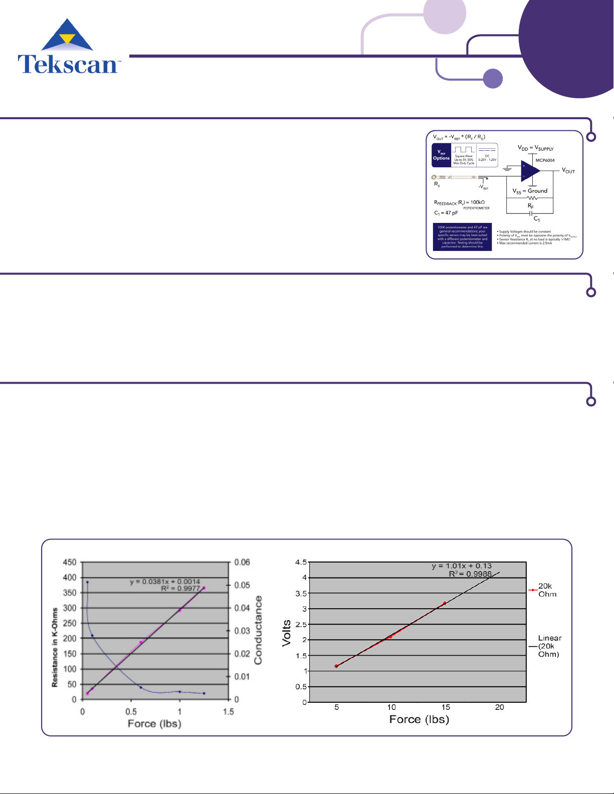
This procedure is meant for use with your own electronics. For testing, Tekscan recommends us-
ing the circuit shown in the diagram at right. Components and instructions for building this circuit
are available with the FlexiForce Starter Kit. You can also purchase a printed circuit board, the
FlexiForce QuickStart Board. If no circuit is available, you can use a multimeter, and measure the
resistance in kilo-ohms.
Part 1: Before Calibrating: Conditioning & Loading Considerations
Before using the sensors it is recommended that you condition the sensors. This process will “break in” the sensor and should be done before
calibration and before every use for best results. The sensors should be loaded with a force that is normal to the plane of the sensor, and 100%
of this force should be transferred through the sensing area (silver circle). If the contact area of the load is too large for the sensing area, then
you can use a puck (small force concentrator) to ensure that all of the force travels through the sensing area.
Place 110% (or more) of maximum test load onto the sensor for approximately 3 seconds. For example, if the maximum test load is 10 pounds,
place 11 (or more) pounds onto the sensor. Remove the load from the sensor. Repeat 4-5 times. When nished, proceed to Part 2: Calibration.
Part 2: Calibration for Static Forces
STEP 1. Place 1/3 of the test weight on the sensor. Leave the weight on the sensor the same amount of time (before recording the out-
put) as you will in your actual experiment. This helps minimize the drift error. Record the output, then remove the weight from the sensor.
STEP 2. Place 2/3 of the test weight on the sensor, and again wait the approximate amount of time. Record the output. Remove weight.
STEP 3. Place the full test weight on the sensor, and again wait the approximate amount of time. Record the output. Remove weight. If
using the recommended circuit, three sets of data are adequate. If using a multimeter, gather two more sets of data for a 5-point chart.
STEP 4. Gather each data set (Sensor Output vs Force applied) and plot data on a graph. If using a multimeter, sensor output is plotted as
Conductance (1/Resistance) vs. Force (Chart A below). This gives a linear plot. Then draw a line of best t, or calculate one with MS Excel.
If using our recommended circuit or your own electronics, sensor output should be plotted as Voltage vs. Force (Chart B below).
STEP 5. Use the equation for the line of best t and sensor output to determine force of unknown loads on sensor during experiment.
Chart A Chart B
Note: If testing involves dynamic forces instead of static force, this must be accounted for in the calibration process. The FlexiForce
sensor should be calibrated in the same time period as the dynamic event that you intend to measure.

+1.617.464.4283 1.800.248.3669
|
info@tekscan.com
|
www.tekscan.com/es
Rev G 08-04-2020 ISO 9001:2008 compliant & 13485:2016 registered
Part 3: Adjusting Full Scale Force Range with Recommended Circuit
The force range of the FlexiForce Sensors can be increased by lowering the drive voltage applied to the sensor and/or by lowering the resis-
tance value of the feedback resistor. Conversely, the sensitivity can be increased (for a lower force range) by increasing these values:
STEP 1. Start with a drive voltage (VT) value of ~1V applied to the sensor, and a feedback resistor (RF) value of 10kΩ.
STEP 2. Apply the maximum calibration force/weight to the sensor. This force should be approximately equal to the maximum force you
will be measuring in your application.
STEP 3. Reduce or increase the drive voltage, VT, until the circuit output is as close as possible to 4.5 volts.
STEP 4. Then “ne tune” by reducing or increasing the feedback resistor, RF, until the circuit output is 4.5 volts.
Please visit http://www.tekscan.com/flexible-force-sensors for additional specications and getting started information.
Available at Tekscan’s Online Store: http://www.tekscan.com/store/
1
Standard FlexiForce Sensors:
FlexiForce Sensors are single-point force sensors available in a
range of congurations and varying force range options.
1
FlexiForce Signal Conditioning Circuits:
With the FlexiForce Starter Kit you can build your own drive cir-
cuits for the sensors. Or, get started quickly with the FlexiForce
QuickStart Board. Both options include 2 Free A201 sample
sensors and provide an 0-5V analog voltage output.
Complete Force Measurement Systems:
Our Economical Load and Force Measurement Systems (ELF)
deliver a complete and robust solution combining force sen-
sors, data acquisition software and USB electronics.
Also available in a new wireless conguration (WELF2)!
Adjusting full scale force range with VTTrim Pot Adjusting full scale force range with RFEEDBACK Trim Pot
Other manuals for FlexiForce
1
Table of contents
Other Tekscan Accessories manuals


