tekton 5470 User manual

BOTTLE JACK
®
Model 5470, 5475,
5480, 5485, 5490,
5495, 5496
OPERATOR’S MANUAL
STORE THIS MANUAL IN A SAFE
PLACE FOR FUTURE REFERENCE
Save time, contact us first.
888-648-8665
NEED HELP?
!
?

READ AND UNDERSTAND ENTIRE MANUAL BEFORE OPERATING JACK. FAILURE TO
FOLLOW INSTRUCTIONS OR WARNINGS COULD RESULT IN PERSONAL INJURY
AND/OR PROPERTY DAMAGE.
Important Safety Rules
ADDING HYDRAULIC OIL
1. Place the jack upright on a level work surface.
2. Ensure ram and pump piston are completely in down position.
3. Remove hydraulic oil plug.
4. Fill hydraulic oil reservoir to level of fill hole.
5. Bleed air from hydraulic system (see following section for instructions).
6. Replace hydraulic oil plug.
BLEEDING AIR FROM HYDRAULIC SYSTEM
1. Place the jack upright on a level work surface.
2. Remove hydraulic oil plug.
3. Fit narrow end of pump handle over release valve screw and open 1-1/2 turns counterclockwise.
4. Insert pump handle into socket and pump rapidly 10 times to purge air from system.
5. Fit narrow end of pump handle over release valve screw and close (turn clockwise until tight).
6. Top off hydraulic oil reservoir to level of fill hole and replace hydraulic oil plug.
STORAGE AND LUBRICATION
To protect jack from damage and corrosion, be sure ram and extension screw are fully retracted and
pump piston is fully in down position before storage. Store jack upright in a dry location.
To prolong life of jack and assure reliable operation, lubrication may be applied when needed. Apply light
machine oil to all pivot points, extension screw, piston, and ram. Never use solvents on any part of jack.
LIFTING
1. Place jack only on a hard, level surface that can support weight of load and solid enough to
prevent base of jack from sinking or shifting.
2. Assemble two pieces of pump handle and press together firmly.
3. Fit narrow end of
pump handle
over
release valve screw
and close by turning clockwise until tight.
4. Position jack under load to be lifted at a secure point strong enough to support stress of
lifting. When lifting vehicles, consult vehicle manufacturer’s manual for approved lifting points.
Turn off vehicle engine, shift vehicle into park or lowest gear, engage parking brake, and chock all
wheels not being lifted. Place chock in front and back of each wheel to prevent rolling.
5. Adjust extension screw to establish solid, secure contact between saddle and load.
6. Insert pump handle into socket and operate up and down until load is raised to desired height.
7. Immediately insert supports (jack stands, if lifting vehicle) under load.
LOWERING
1. Visually inspect area under load before lowering. Be sure it is cleared of bystanders.
Remove load supports or jack stands.
2. Remove pump handle from socket and fit narrow end of pump handle over release valve screw.
Open by slowly turning counterclockwise until jack begins to lower.
Keep all body parts out from under load while lowering! Turn release valve screw very
slowly! Less than 1/8 rotation is needed to begin lowering. Continue to adjust release valve
screw carefully to control descent until load is stable and jack is completely disengaged
from load.
3. Turn extension screw clockwise until fully retracted.
4. Remove jack from beneath load and push ram completely down into jack before storage.
Operating Jack
Maintaining Jack
1. Do not exceed the lifting capacity listed on this bottle jack.
2. This jack is intended for lifting only. Never use jack as a support. Once load is lifted, it must be
supported immediately with a suitable structure (jack stands, if lifting vehicle) capable of bearing load.
Never work on, under, or around a load supported only by a jack.
3. When lifting vehicles, use only approved lift points as specified in vehicle manufacturer’s manual.
Turn off engine, apply parking brake, and use wheel chocks to prevent vehicle from rolling.
4. Operate jack only on a hard, level surface capable of bearing weight of load.
5. Clear all bystanders from work area before lifting load.
WARNING

Parts Reference
Saddle
Carry Handle
(#5495 and #5496 only)
Carry Handle
(#5490 only)
Extension Screw
Ram
Narrow End of Handle
(for adjusting release valve screw)
Pump Piston
Pump Handle (2 Pieces)
Release Valve Screw
Base
Socket
Hydraulic Oil Plug
Hydraulic Oil Reservoir

Ram does
not advance
Problem Solution
Ram does
not fully extend
Ram extends but
loses pressure
Jack leaks oil
Ram will
not retract
Erratic
performance
- Ensure release valve screw is closed. Turn clockwise to close.
- Check hydraulic oil reservoir for proper oil level.
- Bleed air from hydraulic oil reservoir (see page 2)
- Check hydraulic oil reservoir for proper oil level.
- Ensure release valve screw is closed tightly. Turn clockwise to close.
- Check oil reservoir for proper oil level.
- Bleed air from hydraulic oil reservoir (see page 2)
- Ensure hydraulic oil plug is closed tightly.
- Ensure release valve screw is closed tightly.
- Ensure release valve screw is open. Turn counterclockwise to open.
- Debris or rust could cause ram to stick. Clean/lubricate exposed
section of ram.
- Check hydraulic oil reservoir for proper oil level.
- Bleed air from hydraulic system.
Troubleshooting Guide
5470 4000 lb. (1818 kg) 7-3/4" (19.5 cm) 2" (5 cm) 13-7/8" (35.25 cm) 3-1/2" x 3-5/8"
(9 cm x 9.25 cm)
5475 8000 lb. (3636 kg) 7-1/4" (18.4 cm) 2-3/8" (6 cm) 15-1/8" (38.5 cm) 4-3/8" x 4-1/8"
(11 cm x 10.5 cm)
5480 12000 lb. (5454 kg) 8-1/2" (21.5 cm) 2-3/4" (7 cm) 17-1/4" (43.8 cm) 4-3/8" x 4-3/8"
(11 cm x 11 cm)
5485 16000 lb. (7272 kg) 9" (23.8 cm)
3-7/8" (9.8 cm)
18-3/4" (47.5 cm) 4-3/4" x 4-3/4"
(12 cm x 12 cm)
5490
24000 lb. (10910 kg)
9-1/4" (23.5 cm)
3-1/4" (8.25 cm)
18-5/8" (47.3 cm) 5-1/2" x 5-1/4"
(14 cm x 13.3 cm)
5495
40000 lb. (18180 kg)
9-1/2" (24 cm) 2-3/8" (6 cm) 18-1/8" (46 cm) 6-3/8" x 6"
(16 cm x 15.25 cm)
5496
40000 lb. (18180 kg)
7-1/2" (19 cm) 2-3/8" (6 cm) 14-1/4" (36 cm) 6-3/8" x 6"
(16 cm x 15.25 cm)
Model Lifting Capacity Min. Clearance Adj. Screw Max. Lifting Height Base
Capacities and Dimensions
© Copyright 2013
Michigan Industrial Tools
TEKTONTOOLS.COM
Michigan Industrial Tools
3707 Roger B. Chaffee Dr.
Grand Rapids, MI 49548
This manual suits for next models
6
Popular Jack manuals by other brands
Compac
Compac 15tc instruction manual

SilverStone
SilverStone HM50 instruction manual
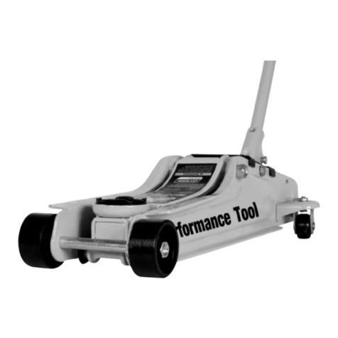
Performance Tool
Performance Tool W1613 owner's manual
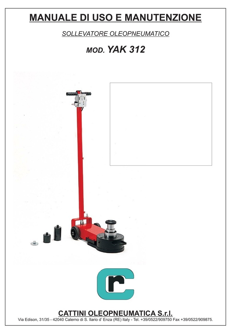
Cattini Oleopneumatica
Cattini Oleopneumatica YAK 312 Operating and maintenance manual
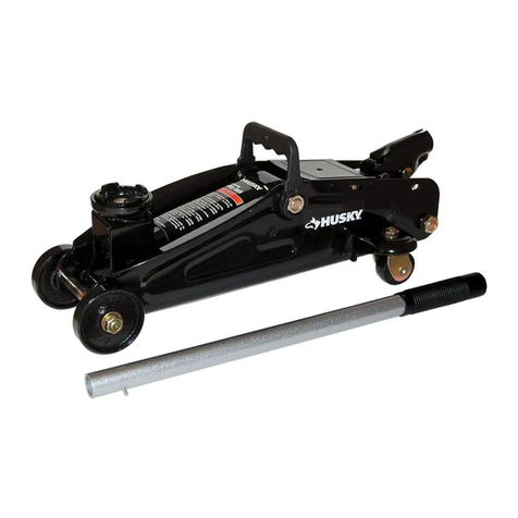
Husky
Husky HPL4136-VT Use and care guide
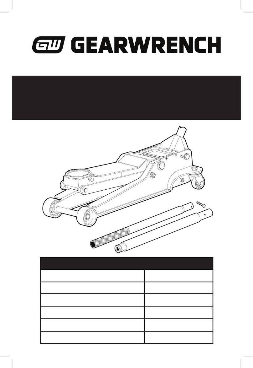
Gearwrench
Gearwrench GWLPFJ3T user manual
Tronair
Tronair 02-0544C0110 Operation & service manual
iTOOLco
iTOOLco REAL PALLET JACK user guide
HEIN-WERNER AUTOMOTIVE
HEIN-WERNER AUTOMOTIVE HW93720 Operating instructions & parts manual

Pittsburgh
Pittsburgh 56374 Owner's manual & safety instructions
Ultra-Fab
Ultra-Fab ULTRA 3502 Installation & operation
Raider
Raider RD-TJ03 user manual
