tekton TRQ62103 User manual

SPLIT BEAM
TORQUE WRENCH
TRQ62103 - 3/8 in. Drive Split Beam Torque Wrench (20–100 .-lb.)
TRQ62203 - 1/2 in. Drive Split Beam Torque Wrench (40–250 .-lb.)
Product Manual
Before using the torque wrench, be sure to read and understand the entire manual.
This tool is a precision measuring instrument that should be operated, stored, and
maintained with care. Failure to follow instructions could result in damage to the
tool, damage to property, or injury.

Flip the cover down to
access the adjustment knob.
Turn the adjustment knob
to the desired torque value.
Replace the cover over the
adjustment knob to secure
it during use. Confirm the
torque setting is accurate.
Determine the required torque for your application in foot pounds (ft.-lb.). Use the
conversion scale on the torque wrench to convert Nm to ft.-lb. If needed, use page 4
to convert other torque units to foot pounds.
INTERNAL MECHANICS
SETTING THE TORQUE VALUE
Click!
OPERATION
1
Conversion Scale
Torque wrench operates
and measures in the
clockwise direction only.

1
2
3
4
Don't use extensions on the handle.
The torque measurement will be
inaccurate and the tool could
become damaged.
STOP applying torque when you hear and
feel a click. This means you’ve reached the
desired torque value.
2
Click!
APPLYING TORQUE
OPERATION
For off-axis tools, like a crowfoot
wrench, calculate a leverage
adjustment on page 5.
Attach a drive tool to the drive tang.
The flex joint provides clearance for
working around obstacles but, when
flexed, can reduce accuracy by up to
4 percent due to the offset from the
plane of rotation.
Engage the drive tool on the fastener
or fitting. For the most accurate
reading, the ratchet head must be
parallel with the wrench body.
Grip the center of the handle and apply
torque SLOWLY in a clockwise direction.
Don't use the torque wrench on
electrical circuits. The handle
doesn’t provide insulation from
electrical current.
Center of Handle
Parallel Flexed
Flexed

• If the torque wrench is not used regularly, operate it several times at a low torque
setting to redistribute lubricant to the internal moving parts.
• The components in the handle are lubricated for life and should not be oiled. The
ratchet head may be lubricated for smooth use as needed.
• Clean the wrench by wiping it with a clean, dry, lint-free cloth. Do not immerse the
wrench in any type of liquid or cleaner to avoid damaging the internal components.
• The torque wrench should only be serviced or recalibrated by an accredited
measurement laboratory.
The ratchet head can be disassembled, if needed, for lubrication or service. Don’t
disassemble other parts of the wrench.
TORQUE WRENCH DIAGRAM
TORQUE WRENCH CARE
This tool is a precision measuring instrument that should be operated, stored, and
maintained with care.
STORAGE
MAINTENANCE
• Store the torque wrench in the storage case in a dry location.
• The torque wrench can be stored at any torque setting because of its internal design.
By comparison, other torque wrenches, like click-style models, often have to be
stored at the lowest torque setting.
3
Ratchet
Head
Flex
Joint
Adjustment
Knob
Cover Center of
Handle
Torque
Setting
Conversion
Scale Handle

FOOT
POUNDS
(.-lb.)
1
2
3
4
5
10
15
20
25
30
35
40
45
50
55
60
65
70
75
80
85
90
95
100
110
120
130
140
150
160
170
180
190
200
210
220
230
240
250
1.356
2.712
4.067
5.423
6.779
13.56
20.34
27.12
33.90
40.67
47.45
54.23
61.01
67.79
74.57
81.35
88.13
94.91
101.7
108.5
115.2
122.0
128.8
135.6
149.1
162.7
176.3
189.8
203.4
216.9
230.5
244.0
257.6
271.2
284.7
298.3
311.8
325.4
339.0
0.1383
0.2765
0.4148
0.5530
0.6913
1.383
2.074
2.765
3.456
4.148
4.839
5.530
6.221
6.913
7.604
8.295
8.987
9.678
10.37
11.06
11.75
12.44
13.13
13.83
15.21
16.59
17.97
19.36
20.74
22.12
23.50
24.89
26.27
27.65
29.03
30.42
31.80
33.18
34.56
13.83
27.65
41.48
55.30
69.13
138.3
207.4
276.5
345.6
414.8
483.9
553.0
622.1
691.3
760.4
829.5
898.7
967.8
1037
1106
1175
1244
1313
1383
1521
1659
1797
1936
2074
2212
2350
2489
2627
2765
2903
3042
3180
3318
3456
12
24
36
48
60
120
180
240
300
360
420
480
540
600
660
720
780
840
900
960
1020
1080
1140
1200
1320
1440
1560
1680
1800
1920
2040
2160
2280
2400
2520
2640
2760
2880
3000
192
384
576
768
960
1920
2880
3840
4800
5760
6720
7680
8640
9600
10560
11520
12480
13440
14400
15360
16320
17280
18240
19200
21120
23040
24960
26880
28800
30720
32640
34560
36480
38400
40320
42240
44160
46080
48000
NEWTON
METERS
(Nm)
KILOGRAM
METERS
(kg-m)
KILOGRAM
CENTIMETERS
(kg-cm)
INCH
POUNDS
(in.-lb.)
OUNCE
INCHES
(oz.-in.)
TORQUE CONVERSION
4
INPUT OPERATION
Units
Torque
Value Units
Torque
Value
OUTPUT EXAMPLE
Nm
kg-m
kg-cm
in.-lb.
oz.-in.
×
0.7376
7.233
0.07233
0.08333
0.00521
ft.-lb.
0.7376
7.233
0.07233
0.08333
0.00521
80 Nm × 0.7376 = 59 .-lb.
59 .-lb. ÷ 0.7376 = 80 Nm
Nm
kg-m
kg-cm
in.-lb.
oz.-in.
ft.-lb.
FORMULA INPUTS
The amount of leverage that's applied to a fastener is affected by the position of a
drive tool in relation to the torque wrench's drive tang. When using an off-axis tool that
doesn’t align with the drive tang, such as a crowfoot wrench, you may need to adjust
your torque setting.
T1 — Torque specification for the fastener
L— Effective length of the torque wrench
TRQ62103: L = 15.62 in.
TRQ62203: L = 19.22 in.
C— Change in length caused by a crowfoot wrench or other drive tool that
doesn’t align with the drive tang
T2 — Torque value you should use
LEVERAGE ADJUSTMENT
T1 × = T2
L
L + C T1 × = T2
L
L + (-C)
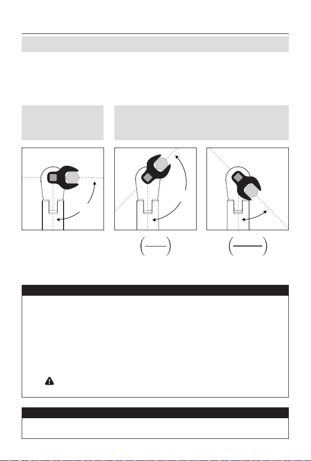
90º
>90º
<90º
5
If possible, align the
drive tool at a 90-degree
angle to the drive tang.
If a different angle is required, use one of the formulas
below to determine the appropriate torque value.
No formula is needed. Set
the torque value to the
fastener’s specification.
FORMULA OUTPUTS
Measure from the center of the fastener to the center of the drive tang in
a line parallel to the body of the wrench.
See Example 1 See Example 2
CALCULATION

Example 1
Example 2
Center of Handle
Center of Fastener
Center of Drive Tang
T2 = Torque Value
T1 = Torque Specification
for Fastener
L = Effective Length
C = Change in
Length
80 .-lb. × = 75.7 .-lb.
19.22 in.
19.22 in. + 1.1 in.
6
>90º
T1 = 80 ft.-lb.
C = 1.1 in.
80 .-lb. × = 84.9 .-lb.
19.22 in.
19.22 in. + (-1.1 in.)
<90º
T1 = 80 ft.-lb.
C = 1.1 in.
LEVERAGE ADJUSTMENT
DIAGRAM

We stand behind our products. 888-648-3371
tekton.com/support
KEEP THIS MANUAL IN THE STORAGE
CASE FOR FUTURE REFERENCE
This manual suits for next models
1
Table of contents
Other tekton Power Tools manuals


