WABECO CC-F1220 hs User manual

Operating instructions
CNC milling machine
with tool changer
CC-F1220 hs

2
Please read before putting into operation for the rst time!
Every person that operates the machine, maintains or repairs it, must have read
the operating instructions, and in particular, the safety notes prior to putting the
machine into operation. Please store these documents for subsequent use
Original version in German/translation in English
Dear Customer!
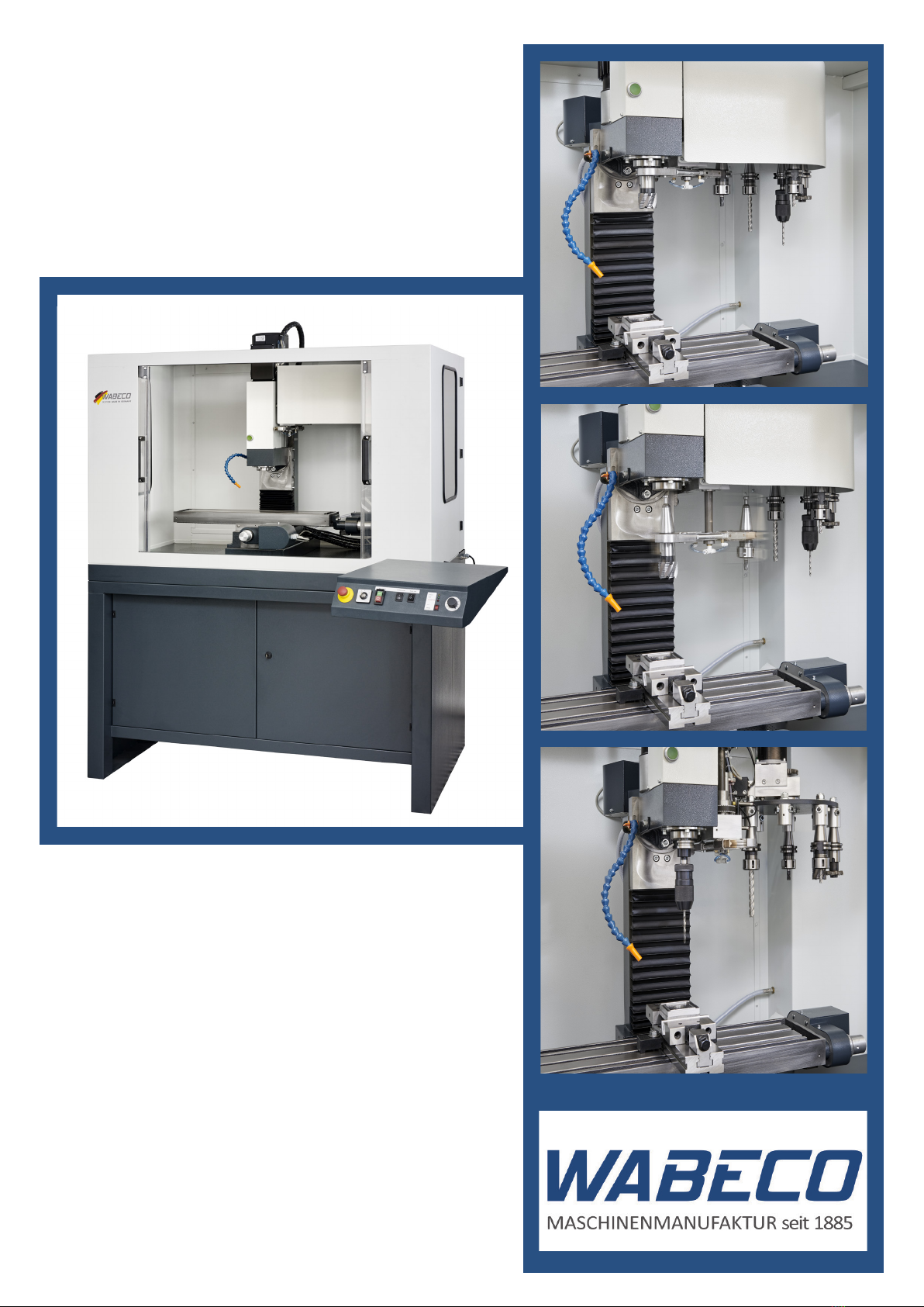
With the purchase of the WABECO machine you have decided in favour of a quality tool. This machine
has been manufactured with the greatest of care and subject to precise quality controls.
These operating instructions are designed to help your to use your new machine safely and correctly.
For this reason, we ask you to read the appropriate notes through attentively and to take care to observe
them.
After unpacking the tool, check whether any transportation damages have occurred. Complaints, wha-
tever their nature, should be communicated immediately. Subsequent claims cannot be recognised.
For all queries and replacement part orders, please always specify the machine number (see type
plate).
Reprinting and reproductions of any kind, even extracts, require the written permission of
WABECO
The transportation and protective packaging is made of the following materials:
■Corrugated card
■Polystyrene without Freon
■Polyethylene foil
■Timber as single-use pallet (untreated)
■Euro pallet (multiple use packaging)
If you no longer need the items, or you do not want to reuse them, dispose of these items at the ofcially
recognised recycling points.
The machine is manufactured in such a way that 98% of the used materials that can be recycled, for
example, steel, cast iron, aluminum and only 2% are chemical materials, e.g. cable sleeves of electrical
cables, PCBs.
If you have any difculties in disposing of these parts properly, we would be happy to help: with prior
agreement we will take back the machine in full and dispose of it. You must, however, cover the costs
of sending it to us.
Disposing of the machine
wabeco-rs.de
Walter Blombach GmbH
42899 Remscheid
Am Blaffertsberg 13
Germany
Phone +49 (0)2191 597-0
Fax +49 (0)2191 597-42
E-Mail [email protected]
Status at 06/2018

3
Index
Declaration of conformity 5
1. Important safety notes 6
1.1 Intended use 6
1.2 Improper and incorrect use 6
1.3 Modications to the machine 6
1.4 Safety regulations for proper use 6
1.5 Safety features 9
1.6 Explanations of the symbols 10
2. Delivery and set up 11
2.1 Transporting the machine 11
2.2 Installation of the machine 12
3. Putting into operation 13
3.1 Connecting compressed air supply 13
3.2 Setting up and connecting the control computer 13
4. Specications regarding the machine 14
4.1 Identication of the model 14
4.2 Declaration of noise levels 14
4.3 Technical data 15
4.4 Dimensions 17
4.5 Revolution setting 18
4.6 Electrical equipment 19
5. Achieving optimum results and avoiding incorrect usage 19
6. Inserting tools into the main spindle 21
6.1 Loading an empty tool magazine 22
6.2 Tool exchange 23
7. Installation and removal of collets 24
7.1 Installation 24
7.2 Removal 24
8. Adjustment of the dovetail guides 25
9. Coolant unit 26
9.1 Safety regulations for the handling of cooling lubricant 26
9.2 Filling the coolant unit 26
9.3 Operating the coolant unit 27
9.4 Positioning the segmented coolant hose 27
9.5 Controlling the ow of coolant using the coolant shut-off valve 28
10. Maintenance 29
11. Lubrication of the machine 30
12. Maintenance of pressure intensier 32
13. Operational faults and the elimination of such 33

4
Index
14. Control elements 34
15. Drawings and legends 36
15.1 Milling head with pneumatic tension 36
15.2 Tensioning mechanism 38
15.3 Z-column with vertical slide 40
15.4 Spindle Z-axis 42
15.5 Cross slide support 44
15.6 Spindle X-axis 46
15.7 Spindle Y-axis 48
15.8 Limit switch X-axis 50
15.9 Limit switch Y-axis 50
15.10 Limit switch Z-axis 51
15.11 Tool changer 52
15.12 Tool support disk 53
15.13 Support arm tool support disk 54
15.14 Gripper 56
15.15 Support arm gripper 58
15.16 Machine safety cabin 60
15.17 Coolant unit 61
15.18 Control panel 62
15.19 Support arm control panel 64
15.20 Machine base cabinet 65
16. Circuit diagram 66
16.1 Overall connection diagram 66
16.2 Axis motor and limit switch connection X-, Y-, Z-axis 67
16.3 NC-rotary table 67
16.4 Axis motor and limit switch connection V-, W-axis 68
16.5 Sensors / relay 69
16.6 Legend for circuit diagrams 70
16.7 Pneumatic diagram tool changer 72
17. NC-rotary table (optional) 73
17.1 Clamping of workpieces on the NC-rotary table 73
17.2 Swiveling the worm shaft in and out 73
17.3 Setting the axial play of the NC-rotary table 74
17.4 Removing the NC drive unit 75
17.5 Setting the axial play of the worm shaft 76
17.6 Setting the axial play of the eccentric tappet 76
17.7 Drawing and legend 77

5
Declaration of conformity
We hereby declare, in the name of the manufacturer
Walter Blombach GmbH
Werkzeug- und Maschinenfabrik
mit Sitz in Remscheid und Neuerburg
D-42871 Remscheid Postfach 12 01 61 Telefon: (02191) 597-0 Fax: (02191) 597-42
D-54673 Neuerburg WABECO Str. 1-10 Telefon: (06564) 9697-0 Fax: (06564) 9697-25
that the following named
CNC milling machine
Type:
CC-F1220 hs
in the serial version, meets the following relevant regulations
- EU Machine Directive 2006/42 EG
- EMC Directive 2014/30/EU
- EU Low Voltage Directive 2014/35/EU
In order to full/implement the requirements of the directives named above, the already published and
applicable standards were drawn upon:
EN ISO 12100:2010
DIN EN 60204-1:2007
DIN EN 13128:2009
Proxy for the compilation of the technical documentation is the operational head of the above named
manufacturer, Mr Christoph Schneider.
D-54673 Neuerburg 2018
________________________________
Place and date of issue
________________________________
Operating head Christoph Schneider

6
1. Important safety notes
1.1 Intended use
The milling machines described in these operating instructions are designed for the processing of metal,
plastic and timber only.
To ensure safe operation of the milling machines, the regulations set out in the chapter: „Safety regula-
tions“ must be observed.
The milling machines described in these operating instructions have been developed and manufactured
for the purpose named above. Walter Blombach GmbH accepts no responsibility for property damage
and personal injury caused as a result of not intended and incorrect use of the milling machines
1.2 Improper and incorrect use
1.3 Modications to the machine
For reasons of safety, it is forbidden for the user to make modications of any type to the milling machine.
Walter Blombach GmbH accepts no responsibility for property damage and personal injury caused as
a result of any modications to the milling machine by the user that have not expressly been authorised
by the company
1.4 Safety regulations for proper use
The machine may represent a source of danger if it is not used correctly. For this reason, it is important
that the following safety regulations are read attentively and observed carefully.
Every person that operates the machine, maintains or repairs it, must have read the operating instruc-
tions, and in particular, the safety notes prior to putting the machine into operation.
In order to full these requirements, these operating instructions must accompany the machine throug-
hout its entire lifetime and be available for research.
In the event that the machine changes owners, the operating instructions must thus be passed on to the
new owner along with the machine

7
1. Important safety notes
1.4 Safety regulations for proper use
1. Only specially trained persons may operate the machine. The guarantee and warranty are voided
if damages are caused by improper operation.
2. We remind you that no liability will be accepted for damages caused by not observing these ope-
rating instructions.
3. The operator of the machine is to ensure that at least one copy of the operating instructions is
stored in the immediate vicinity of the machine and available to the people who work with the
machine.
4. The operator is to ensure that the safety and danger notications on the machine are observed
and that the signs are kept in a legible state.
5. Do not work without goggles.
6. Wear close tting clothing and, if you have long hair, wear a hair net. Do not wear loose tting or
loose items (ties, shirt sleeves, jewellery etc.).
7. Gloves may not be worn.
8. In the event of an emission noise level as of 80 dB (A) at the workplace, ear defenders must be
worn.
9. The machine may not operate without supervision.
10. Secure your machine in such a way that it cannot be switched on by children. Persons who have
not been trained may not operate the machine.
11. Before using the machine, make sure it is in good working condition. Pay special attention to any
damage to the grounded plug or the electrical connections. Never operate the machine with a
defective, crushed or exposed cable.
12. Plug the grounded plug into a suitable socket for the machine. The cable for the machine may
only be connected to a safety socket or a connection box. Have the safety socket or connection
box checked by an electrical specialist before hand.
13. The safety socket or connection box must be close enough to the machine that the power cable
is not under strain.
14. When carrying out maintenance and cleaning work, the machine must be switched off and the
grounded plug pulled out.
15. Set-up work is only to be carried out with the machine switched off.
16. Do not reach into the operating machine.

8
1. Important safety notes
1.4 Safety regulations for proper use
17. Remain with the machine until it has come to a standstill.
18. Only have repairs carried out by a qualied specialist! Repair work may only be carried out by
persons who are qualied for the relevant repairs and who are familiar with the appropriate health
and safety requirements.
19. Protect the machine from damp.
20. Constantly check the machine for damages. Replace damaged parts only with original parts and
have these replaced by a specialist. The guarantee and warranty is voided if accessories and
replacement parts are use that are not designed for the machine.
21. To avoid insufcient lighting, we recommend setting up a light source that provides a value of at
least 500 Lux at the tool‘s cutting edge.
22. Do not remove the generated shavings with your hand. Use the appropriate tools (hand-held
sweeper, hook, brush).
23. Never change tools and workpieces while machine is running.
24. Tools and workpieces may never be changed when the machine is running.
25. Workpieces must be secured by suitable xtures e.g. prisms, machine vice etc..
26. Chuck keys or similar tools may not be attached to the machine to ensure that they cannot be
caught by the spindle and thrown about.
27. Never reach into the spindle opening of the main spindle with ngers (risk of crushing).
28. The set-up mode may only be executed by qualied specialists.
29. Return the operation selection switch to CNC operation after completion of set-up mode and
remove key.
30. The magazine of the tool changer may only be loaded and unloaded via the spindle of the
machine.

9
1.5 Safety features
1. Important safety notes
In order to allow for safe working with our machines, we have provided the following safety installations
and thus comply with the relevant European safety requirements
■Machine safety cabin
In CNC mode, the door to the machine safety cabin must be closed in order for the milling
machine to work in CNC operation.
■ON/OFF switch with under-voltage trigger
The ON/OFF switch is tted with an under-voltage trigger, thus, in the event of a power
failure, the machine does not switch itself back on automatically. This prevents risks caused
by the unexpected motion of the tool spindle.
■Emergency off switch
The emergency off switchacts to quickly stop the machine.
■Overload protection
The machine is tted with an overload protection feature. This overload protection feature
switches the main drive motor off automatically when the machine is overloaded.
The machine can only then be switched on after a waiting period.
■Switch for operational modes
The switch for operational modes has 3 settings (CNC operation - zero setting - set-up mode)
which can only be selected via a key. Once the operational mode has been selected, the key
can be removed which prevents unauthorised changing of the operational mode.
Working in CNC mode is only possible with a closed door. The door is locked as soon as the
main spindle starts. If the door is open, the main spindle cannot be started.
Working in set-up mode can be executed while the door is open. The switch for operating
modes has to be set to set-up mode.
The main spindle can thus be activated by closed as well as open door.
■Pressure monitor
The compressed air supply for the machine and/or the required systems pressure is checked
by the pressure monitor. If the systems pressure drops below the critical value for any
reason (e.g. burst hose), the machine automatically switches to failure. The machine can
only be restarted once the error has been removed.

10
1. Important safety notes
1.6 Explanations of the symbols
With a measured noise level of 80 dB (A) at the workpla-
ce the operator should wear Ear Protection.
Caution:
Always pull the power plug prior to any maintenance
work!
Read the operating instructions prior to initial operation or
maintenance work!
Caution:
Dangerous electric voltage
If the gripper of the tool changer is not swiveled in, the
positioning of the main spindle
(Z-axis) is admissible.
If the gripper of the tool changer is swiveled in, the posi-
tioning of the main spindle, (Z-axis) is not admissible. If
applicable, the gripper has to be swiveled out manually.
The operating pressure for the tool changer has to be set
to 5 bar at the pressure regulator of the machine.

11
The place of set up should be selected in such a way that
■ There is sufcient lighting
■The electrical power supply with safety socket and earth are installed close enough to the machine
that the power cable is not subject to any strain.
The machine has to be screwed to the installation surface and/or provided with a safe stand by using
level elements. For this purpose, the machine base cabinet of the machine has four xation thread bores
(M10) as well as four xation bores (Ø 12.5 mm).
The doors of the machine safety cabin can only be opened if the machine is switched to operation
modes CNC or set-up if the main spindle is not moving.
2. Delivery and set up
2.1 Transporting the machine
To transport the machine it is advisable to lift it at the lower cabinet with a forklift or platform trolley and
carefully move it to the desired location. If possible, use wide forks (max. 1260 mm). We recommend
using an intermediate plate for optimal load distribution and the protection of the machine. For example,
a Euro-pallet of 1200 x 800 mm is suitable.
Machine with machine safety cabin and machine base cabinet
Pallet for improved distribution of load
Forklift truck / pallet truck

12
2. Delivery and installation
2.2 Installation of the machine
The appropriate bores for the installation of the machine safety cabin onto a WABECO machine base
cabinet are already provided. The machine base cabinet ensures secure positioning of the milling ma-
chine and/or machine safety cabin.
If the machine safety cabin is installed on another suitable installation surface, the 8 through-bores have
to be drilled in the customer‘s installation surface. The positions of the 8 xation threads (thread M8)
of the machine safety cabin are illustrated below. The diameter of the through-bores in the installation
surface has to be at least 9 mm.
The hexagon bolts (M10) included in the scope of delivery of the machine base cabinet can be used for
adjustments. For this purpose, rst screw the hex nut (M10), which are also included in the scope of de-
livery, to the hex bolts. Subsequently, insert the screws equipped with nuts into the four provided threads
from below in the machine base cabinet. The machine base cabinet can now be adjusted by tightening
or loosening the screw. Once the machine base cabinet is adjusted, you can counter the hexagon bolts
with the nuts on the screws to secure their position.
Good work results and low vibration running are only possible if the above mentioned prerequi-
sites for mounting are complied with.

13
3. Putting into operation
■Use a dry cloth to remove the corrosion protection that was applied to all exposed parts for transport
■In the event of marine impregnation of exposed parts, it is recommended you spray them with oil,
allow it to work, and then remove the impregnation with a dry cloth.
■Once set up properly (see the section on delivery and set up) connect the grounded plug directly to
a safety socket and the 230 V 50/60 Hz (optional 110 V 60 Hz) mains power supply.
■ Provision of sufcient coolant for the operation of a coolant unit
■(optional)
■Release the axis clamps and check the individual feed spindles for easy operation
■Check all electronic control elements, for example, ON/OFF switch, emergency off switch, potenti-
ometer etc. for functionality.
3.1 Connecting compressed air supply
Prior to operating the machine, it has to be connected to suitable compressed air supply. Only non-lubri-
cated compressed air at a pressure of at least 5 bar may be added. The operating pressure for the tool
changer has to be set to 5 bar at the pressure regulator of the machine.
The tool changer of the milling machine possesses three compressed-air-operated movement mecha-
nisms. These are the up and down movement of the gripper, the opening and closing of the gripper jaws
as well as the opening and closing of the tool clamps of the main spindle.
Before connecting the compressed air supply, you have to ensure that no people or objects are in the
danger zone of the tool changer and that the doors of the cabin are closed. Please ensure also that the
gripper is located parallel to the main spindle and that no tool has been inserted.
Attention: The gripper is oved directly upward when connecting the compressed air supply.
3.2 Setting up and connecting the control computer
When selecting a suitable control computer, pay attention to the system prerequisites of the
control software. These are listed on the rear of the CD case sent with the machine
Follow the instructions in the start manual of the software to install the control software on the computer.
The start manual can be found in the CD case of the control software included with the machine.
In the next step, the software must be adapted to your machine. To do this, follow the instructions sent
with the machine which detail the editing of the parameters.
When the software has been successfully installed on the control computer and all parameters have
been adapted successfully, the control computer must be connected with the machine controller.
The machine controller communicates with the computer via the serial interface (COM port). In order to
establish a connection between the machine controller and the computer, connect the end of the inter-
face cable that is on the machine console to the COM port of the computer.
CAUTION:
The axial cable of the step motors and the serial interface cable may only be plugged in or remo-
ved when the controller is switched off. Otherwise this may lead to damage to the controller, the
machine or the control computer

14
4.2 Declaration of noise levels
Declaration of noise levels in accordance with DIN EN ISO 3744
Emission values in idle
Emission sound pressure level at the workplace
at 50 % = 74.8 dB (A
at 100 % = 76.4 dB (A)
Sound power level
at 50 % = 84.1 dB (A)
at 100 % = 80.3 dB (A)
At an emission sound pressure level from 80 dB (A) and above at the workplace
ear protection is required.
4. Specications regarding the machine
4.1 Identication of the model
The precise model designation of your machine can be found on the type plate attached to the machine.

15
4. Specications regarding the machine
4.3 Technical data
Working range
Longitudinal travel X-axis 500 mm
Transverse travel Y-axis 150 mm
Vertical travel Z-axis 280 mm
Distance milling table - tool spindle min. 110 mm - max. 390 mm
Outreach tool spindle - Z-column 185 mm
Machine precision
True running accuracy of the tool spindle 0.01 mm
Positioning accuracy ± 0.015 mm
Main drive motor
Frequency-controlled main drive motor
230V, 50/60 Hz 2.0 kW
Electronically innitely variable drive 100 - 7500 rpm
Due to high speed suitable for small workpieces e.g.
for engraving work
Main drive motor with overload protection
Electronics
Electronics manufactured in accordance with the VDE (Association of
German electronics engineers)
Constant torque throughout the entire speed range
Tool spindle
Tool holder ISO30 DIN 69871
Tightening thread DIN 69872
Arranged with re-adjustable anti-friction bearings
High torque even in the lowest speed range
e.g. for machining hard-to-cut materials
Wide toothed belt between motor and tool spindle
ensures a slip-free drive and a smooth running
Z-column and coordinate table
Made of ribbed gray cast iron
Work table 700 x 180 mm
Number of T-slots 3
Width of T-slots 12 mm
Center distance between T-slots 50 mm

16
4. Specications regarding the machine
4.3 Technical data
Spindles
High precision ball screws
Stepper motors
Maintenance-free
Travel speed (rapid traverse) X-and Y-axis 30 - 1200 mm/min
Travel speed (rapid traverse) Z-axis 30 – 800 mm/min
Power bipolar
Step angle 1.8°± 0.09
Resistance 0.3 Ohm
High feed and acceleration values
Plug Sub D 9 pol
Industrial control line 3 m shielded cable
Limit switches
For X-, Y- and Z-axis mechanical single limit switches
Tool changer
With double gripper system
Magazine stations 8
Tool change time 6 seconds
Tool diameter max. 50 mm
Tool weight max. 2.3 kg
Demand for compressed air 6 bar
Machine safety cabin
With integrated coolant unit
Content coolant 72 liter
Feed pump 230 Volt, 50/60 Hz
Dimensions and weight
Machine dimensions without packaging W1420 x D1000 xH1310
Weight without packaging 340 kg

17
4. Specications regarding the machine
4.4 Dimensions

18
4. Specications regarding the machine
4.5 Revolution setting
Depending on the material (e.g. steel, aluminum), a specic cutting speed is required for milling.
In order to always be able to select a cutting speed suitable for the material of the workpiece and the
milling diameter, the revolutions of the tool spindle can be innitely adjusted at the potentiometer from
100 to 7500 rpm in the 2.0 kW motor.
The potentiometer ((8) of the control panel) allows the innite setting of the revolutions of the tool spindle
from 100 to 7500 rpm. In order for the revolutions to be activated correctly via software, the potentiome-
ter must be set to 100%. During the operation it can be used to minimally adjust the revolution according
to the processing conditions
2.0 kW motor
% Revolutions rpm
2 50
3 100
4 200
5 350
10 700
15 1000
20 1400
25 1700
30 2100
35 2500
40 2900
45 3200
50 3600
55 4050
60 4500
65 4800
70 5200
75 5600
80 6050
85 6500
90 6900
95 7200
100 7500

19
4.6 Electrical equipment
The frequency-regulated main drive motor is delivered already installed
■The under-voltage trigger is integrated in the electronics of the motor
■The ON/OFF switch has to be switched on again also after an interruption of power
■If the main propulsion motor is overloaded, it switches off automatically.
■The main propulsion motor can only be reactivated after a short downtime.
■ For this purpose, rst switch the machine off via the ON/OFF switch; wait 5 seconds and reactivate
5. Achieving optimum results and avoiding incorrect usage
■Use of suitable processing tools.
■Adaptation of revolution setting and feed to the material and workpiece.
■Clamp the tool in such a way that the clamping point is as close to the workpiece as possible.
■ Clamp the workpieces rmly and without vibrations.
■The use of coolant and lubrication to increase the durability of the tool, improve surface quality and
accuracy.
■Clamp processing tools and workpieces on a clean clamping surface.
■ Lubricate machine sufciently.
■Set the bearing clearance and guides correctly.
4. Specications regarding the machine

20
5. Achieving optimum results and avoiding incorrect usage
It is recommended that:
■The borer should be tted and tensioned with the key in such a way that the borer is positioned
precisely between the three clamping jaws of the crown gear, quick clamping or collet chuck
■Clamp the milling machine with shaft using the collet chuck and the appropriate collets
■Clamp the milling machine with bored hole and longitudinal groove using the plugged milling
machine spike
When boring, attention is to be paid that:
■The appropriate revolutions are set according to the diameter of the borer
■The pressure is gentle enough that the borer is able to cut without straining
■In the event of too much pressure, the result is early borer wear or even borer breakage or jamming
in the bored hole. In the event of jamming, immediately bring the main drive motor to a stand-
still by pressing the emergency off switch
■When using hard materials, for example, steel, ordinary boring oil must be used
■The borer is always to be removed from the workpiece with the spindle rotating
■When using non-metal materials, for example, wood, tearing on breakthrough can be prevents by
clamping a piece of waste wood under the workpiece to be processed
■For wood workpieces with a veneer or plastic coating, always work from the side with the veneer
■With very thin sheets, also clamp using a piece of waste wood
When milling, attention is to be paid that:
■The appropriate cutting speed is selected (see the section on revolution setting)
■ For materials with normal rmness values, e.g. steel 18-22m/min
■ For materials with higher rmness values 10-14m/min
■The pressure is to be selected so that the cutting speed remains constant
■For hard materials, use ordinary boring oil
When clamping the workpieces, attention should be paid that:
■The appropriate clamping screws are used for the T-slots of the milling machine table or use a ma-
chine vice
■The milling machine table of the cross slide support is to be cleaned of dirt residue and shavings in
order to ensure perfectly even clamping
Table of contents
Other WABECO Power Tools manuals