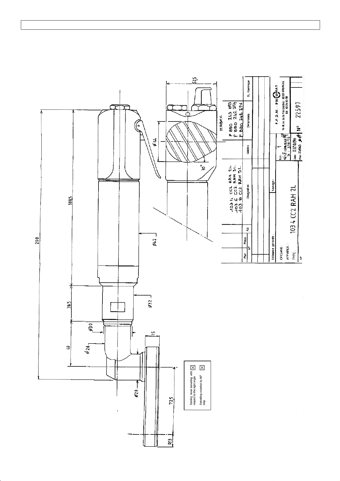
Angle nutrunner PNEUMAT 103 4 CC2 RAH2L H13 X 2 AL /Instructions Manual
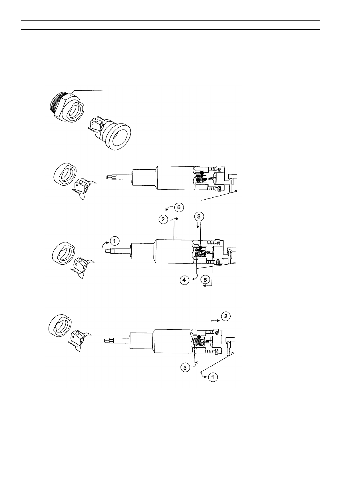
5. TORQUE ADJUSTMENT
Adjustment procedure :
First, of all, adjustment to the utilized torque, the position corresponding to the minimum torque.
Let the screwdriver turn in free rotation in the screwing sense and after having untightened the blocking
screw (43B), turn the adjusting screw (43C) in the negative sense (anticlockwise) until the screwdriver stops.
Release the lever and activate one more time the lever : the screwdriver musn’t turn.
Turn the adjusting screw in the clockwise direction by
half turn and activate the lever at each phase : when
the screwdriver starts, the adjusting torque
corresponds to the minimum torque.
Proceed to the standstill torque value control by
inserting a rotary transducer between the screwdriver
and the tightening socket in accordance with the 5393
ISO standard procedure.
Change the adjustment until obtaining the desired torque by taking up the adjusting screw play before to
unscrew the clamping screw.
We advise you to act on this screw only by succesive half-turn and to make a control after each adjusting
modification.
Do not make any adjustment on a retightening.
After each intervention on the adjusting screw (43C), retighten moderately the blocking screw.
6. UTILISATION CAUTION FOR CROWFOOT NUTRUNNERS
The nutrunners equipped with crowfoot require a particular care. The train of gears wich permits to make
screwings in hard-to-get to zone, is often proportioned in function of the ensambly working environment in
unusual conditions.
In certain cases where numerous pinions are necessary inside the crowfoot, the train of gears reversibility is
not systematic. We advise you against practising a traction on the screwdriver when it has reached its
screwing torque (after locking due to the limiter). It could bring about a retightening of the ensambly, or if this
action was repeated a premature breaking of the crowfoot or of its pinions.
7. ASSEMBLY AND DISASSEMBLY RECOMMENDATIONS
At each disassembly, clean and study carefully all the spare parts before to proceed to the gears and ball
bearings regreasing.
Lubricate lightly the blade housings in the moment of the motor reassembly.
Use only appropriated wrenches. Do not use vice tightening and multiple slip-joint pliers.
Warning :
The presence of a cutting kerf on a nut symbolize a threading on the left. It is recommended to disassembly
frecuently the exhaust silencers and to clean them with a spray gun after having soak them in a degreasing
agent solution in order to preserve the original caracteristic of the tool.
8. LUBRICATION
Unless otherwise stated, pneumatic tools must be feeded with filtered and lubricated air.
It is recommended to install the lubricator the nearer possible of the tool especially during the screwdriver
utilisation. It is also recommended to watch over to the good functionning and to the oil supply adapted
adjustment.
After a prolonged locking, introduce by the feeding connector some crude drops or clean gas oil drops.
-turn the motor in manual by actionning the output spindle.
Blocking screw
Adjusting screw
Adjusting wrench
Male 6 flats wrench of 3 mm