Operating
Instructions--7A18/7A18N
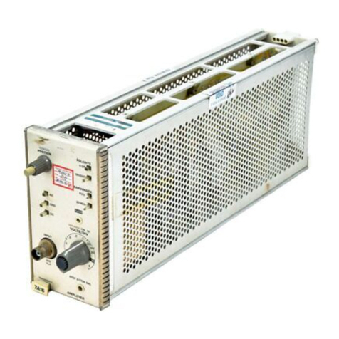
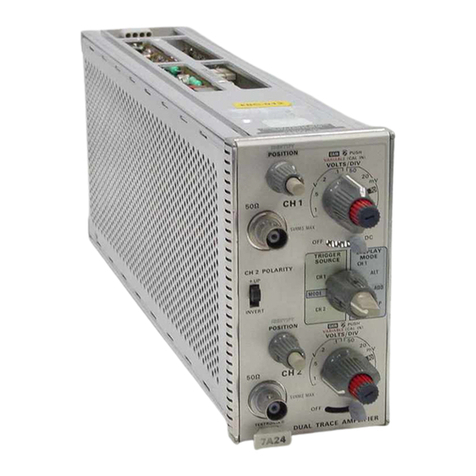
VOLTSIDIV Selects calibrated deflection factors
from
5
mV/Div to
5
VIDiv; ten
steps ina 1-2-5sequence.
VARIABLE Provides continuously variable un-
(VOLTSiDIV) calibrated settings between cali-
brated steps. Extends thedeflection
factor range to 12.5 voltsidivision
or more.
GAlNAdjustment When the VARIABLE control is
pushed in,
it
becomes afront-panel
screw-driver adjustment for cali-
bration of deflection factor.
DISPLAY MODE Selects one of the following modes
of operation:
CH I.--A single-tracedisplay of the
signal applied toChannel
1.
ALT--A dual-trace display of the
signal applied to both channels.
'The channels are alternately dis-
played, and switching occurs at
the end of each time-base
sweep.
ADD-Algebraically adds the signals
applied to the CH 1 and CH 2
input connectors, and the
algebraic sum is displayed on
the CRT. The CH 2 POLARITY
switch allows the display to be
CH 1
+
CH 2 or CH
1
-
CH 2.
Position of the trace in this dis-
play mode is controlled by CH 1
POSITION control only.
CHOP---Adual-trace display of the
signals applied to bothchannels.
The two channels time-sharethe
sweep as determined by the in-
dicator oscilloscope.
CH single-tracedisplay of the
signal applied toCH 2.
TRIGGER SOURCE Selects source of the trigger signal.
The trigger signals provide internal
triggering for the oscilloscope time-
base units.
CH 1
-
internal triggering signal
obtained from signal applied to
CH
1.
MODE-.-,Internal trigger signal auto-
matically follows DISPLAY
MODE selection. In ADD or
CHOP display modes, the trigger
signal is the algebraic sum of CH
1
and CH 2 trigger.
CH 2---Internal trigger signal
obtained from signal applied to
CH 2.
CH 2 POLARITY Provides means of inverting the CH
2 display.
-WP--.A positive-going signal at the
CH
2
input connector deflects
the
CRI
display upward.
INVERT--.A positive-going signal at
the CH
2
input connector de-
flects the CRT display down-
ward.
GENERAL OPERATING INFORMATION
Introduction
For single-trace operation, either of the two identical
amplifier channels can be used independently by setting the
DISPLAY MODE and TRIGGER SOURCE switches toCH
1 or CH 2 and connecting the signal to be observed tothe
appropriate input. In the discussions to follow, single-trace
operations using CH
1
only apply equally to CH 2 only.
Signal Connections
In general, probes offer the most convenient means of
connecting a signal to the input of the 7A18. A 10X atten-
uator probe offers a high input impedance and allows the
circuit under test to perform very close to normal operating
conditions.
The Tektronix P6053A probe, with its readout coding
ring, was designed specifically for use with 'Tektronix 7A-
series amplifier units equipped with readout. The readout
coding ring on the probe connects to
a
circuit inthe ampli-
fier unitwhich automatically corrects the readout displayed
on the CRT to the actual deflection factor at the tip of the
probe being used. For probes to be used with amplifier
units without readout, see the Tektronix, Inc. catalog.
Vertical Gain Check and Adjustment
TOcheck the gain of either channel, set the VOLTSlDfV
switch to 10mVand connect
40
mV, 1kHz signal from the
oscilloscope calibrator to the input connector of the chan-
nel being checked. Thevertical deflection should be exactly
four divisions. If not, adjust the front-panel GAIN for
exactly four divisions of deflection. The GAlN adjustment
is
engaged by pressing in the GAIN control knoband turn-
ing the knob with a narrow-blade screwdriver (see Front
Artisan Scientific - Quality Instrumentation ... Guaranteed | (888) 88-SOURCE | www.artisan-scientific.com
