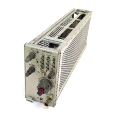
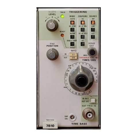
Tektronix 7B92A User manual

Tektronix,
Inc.
P.O.
Box
500
Beaverton,
Oregon
070-1751-02
Product Group 42
97077
COMMITTED
TO
EXCELLENCE
PLEASE CHECK FOR CHANGE INFORMATION
AT
THE REAR OF THIS MANUAL.
7B92A
DUAL
TIME
BASE
INSTRUCTION
Serial
Number
M~~~~§9'
13
0
99170
First Printing JUN 1978
Revised JUN 1987

Scans
By
Artel
Media
Artek Media
1042 P
lummer
Gir.
SW
Rochester,
MN
55902
www.artekmedia.com
"High resolution scans of obsolete technical manuals"
If your looking for a quality scanned technical manual
in
PDF format please visit
our W
EB
si
te at www.artekmedia.com or drop us
an
email at
manuals@artekmedia.com and we will be happy to ema
il
you a current
li
st ofthe
manuals we have available.
If you don't see the manual you need
on
the list drop us a line anyway we may
still be able to point you to other sources. If you have
an
existing manual you
would like scanned please write for details, This can often be done very
reasonably
in
consideration for adding your manual to our library.
Typically the scans
in
our manuals are done as follows;
1) Typed text pages are typically scanned
in
black and white at 300 dpi.
2)
Photo pages are typica
ll
y scanned
in
gray scale mode at 600 dpi
3)
Schematic diagram pages are typically scanned
in
black and white at 600
dpi unless the original manual had colored high lighting (as
is
the case for
some 70's vintage Tektronix manuals).
If you purchased this manual from us (typically through our Ebay name of
ArtekMedia) thank you very much. If you received this from a well-meaning
"friend" for free we would appreciate your treating this much like you would
"share ware".
By
that we mean a donation of at least $5-10 per manual
is
appreciated in recognition ofthe time
(a
ma
nu
al
can take as much as 40 hours to
reproduce, book, link etc.), energy and quality
of
effort that went into preserving
this manual. Donations via PayPal go to: [email protected] or c
an
be
mailed to us the address above.
Dave &Lynn Henderson
Artek Media

Copyright
~.
1974, 1975, 1978 Tektronix, Inc. All rights
reserved. Contents of this publication may not
be
reproduced
in
any form without the written permission of
Tektronix, Inc.
Products of Tektronix, Inc. and its subsidiaries are covered
by U.S. and foreign patents and/or pending patents.
TEKTRONIX, TEK, SCOPE-MOBILE,
and
8 are
registered trademarks of Tektronix, Inc. TELEQUIPMENT
is a registered trademark of Tektronix U.K. Limited.
Printed
in
U.S.A. Specification and price change privileges
are reserved.
INSTRUMENT SERIAL NUMBERS
Each instrument has a serial number
on
a panel insert, tag,
or stamped
on
the chassis. The first number or letter
designates the country of manufacture. The last five digits
of the serial number are assigned sequentially
and
are
unique to each instrument. Those manufactured
in
the
United States have six unique digits. The country of
manufacture
is
identified
as
follows:
BOOOOOO
100000
200000
300000
700000
Tektronix, Inc., Beaverton, Oregon, USA
Tektronix Guernsey, Ltd., Channel Islands
Tektronix United Kingdom, Ltd., London
Sony/Tektronix, Japan
Tektronix Holland,
NV,
Heerenveen,
The Netherlands

@
SECTION 1
SECTION 2
TABLE
OF
CONTENTS
LIST
OF
ILLUSTRATIONS
................................
.
SAFETY SUMMARY
.....................................
.
OPERATING
INSTRUCTIONS
Page
iii
v
INTRODUCTION
........................................
1-1
INSTALLATION
........................................
1-1
FRONT-PANEL CONTROLS, CONNECTORS, AND
INDICATORS.
. .
..
1-2
Main
Triggering
Controls
................................
1-2
Sweep
Controls
. . . . . . . . . . . . . . . . . . . . . . . . . . . . . . . . . . . . .
..
1-4
Delayed
Triggering
Controls
. . . . . . . . . . . . . . . . . . . . . . . . . . . .
..
1-5
Front-Panel
Inputs
. . . . . . . . . . . . . . . . . . . . . . . . . . . . . . . . . . .
..
1-5
FUNCTIONAL
CHECK
....................................
1-5
Setup Procedure
......................................
1-6
Sweep Functions
......................................
1-6
Triggering
Functions
...................................
1-7
GENERAL OPERATING
INFORMATION
.......................
1-8
Main
Triggering.
. . . . . . . . . . . . . . . . . . . . . . . . . . . . . . . . . . . .
..
1-8
Main
Trigger
Modes . . . . . . . . . . . . . . . . . . . . . . . . . . . . . . . . . .
..
1-8
Main
Trigger
Coupling
..................................
1-9
Main
Trigger
Source
...................................
1-10
Input
Impedance
......................................
1-10
Trigger
Slope
........................................
1-10
Trigger
Level.
. . . . . . . . . . . . . . . . . . . . . . . . . . . . . . . . . . . . . .
..
1-10
Selecting Sweep Rates . . . . . . . . . . . . . . . . . . . . . . . . . . . . . . . .
..
1-12
Time
Measurement
....................................
1-12
Display Modes
.......................................
1-12
Delay
Time
Multiplier.
. . . . . . . . . . . . . . . . . . . . . . . . . . . . . . . .
..
1-13
Delayed Sweep
Triggering
...............................
1-13
SPECIFICATION
........................................
2-1
I
WARNING
I
THE FOLLOWING SERVICING
INSTRUCTIONS
ARE FOR USE
BY
QUALIFIED
PER-
SONNEL ONL
Y.
TO
AVOID
PERSONAL INJURY, DO
NOT
PERFORM
ANY
SERVICING
OTHER THAN
THAT
CONTAINED
IN
OPERATlNG
INSTRUCTIONS
UNLESS YOU ARE
QUALIFIED
TO
DO SO.
SECTION 3 THEORY
OF
OPERATION
Block
Diagram
Description.
. . . . . . . . . . . . . . . . . . . . . . . . . . . . . .
..
3-1
Detailed
Circuit
Description
................................
3-1
Main
Trigger
Generator
.................................
3-1
Delaying Sweep Generator
...............................
3-3
Delayed
Trigger
Generator
...............................
3-4
Delayed Sweep Generator
...............................
3-6
Horizontal
Logic
......................................
3-6
Output
Amplifier
......................................
3-7
Readout
............................................
3-7
7892A
7B92A
TABLE
OF
CONTENTS
(cont)
SECTION 4 MAINTENANCE Page
Preventive Maintenance
...................................
4-1
Cleaning
............................................
4-1
Visual
Inspection
......................................
4-1
Lubrication
..........................................
4-1
Semiconductor
Checks
.................................
4-2
Adjustment
After
Repair
.................................
4-2
Troubleshooting
........................................
4-3
Troubleshooting
Aids
. . . . . . . . . . . . . . . . . . . . . . . . . . . . . . . . .
..
4-3
Troubleshooting
Equipment
..............................
4-6
Troubleshooting
Techniques
.............................
4-6
Corrective Maintenance
...................................
4-8
Obtaining
Replacement Parts
.............................
4-8
Soldering
Techniques
..................................
4-8
Component
Removal and Replacement
......................
4-9
Adjustment
After
Repair . . . . . . . . . . . . . . . . . . . . . . . . . . . . . . .
..
4-11
Repackaging For Shipment
..............................
4-11
SECTION 5 PERFORMANCE CHECK/CALIBRATION
Preliminary
Information
.................................
5-1
Test Equipment Required
................................
5-1
Part I Performance Check
.................................
5-4
Outline
for
Part I Performance Check
.......................
5-6
A.
Trigger
Sensitivity
.................................
5-4
B.
Horizontal System
.................................
5-4
Preliminary Procedure
..................................
5-4
A.
Trigger
Sensitivity
...................................
5-5
B.
Horizontal
System
...................................
5-10
Part
II
Calibration
.......................................
5-16
Outline
for
Part
II
Calibration
.............................
5-16
A.
Trigger
Sensitivity (SN B070000-above)
..................
5-16
B.
Trigger
Sensitivity (SN B069999-below)
..................
5-16
C.
Horizontal System
.................................
5-17
Preliminary Procedure
................................
5-17
A.
Trigger
Sensitivity (SN B070000-above)
....................
5-18
B.
Trigger
Sensitivity (SN B069999-below)
....................
5-25
C.
Horizontal System
...................................
5-33
SECTION 6
OPTIONS
SECTION 7 REPLACEABLE ELECTRICAL PARTS
SECTION 8 DIAGRAMS AND
CIRCUIT
BOARD ILLUSTRATIONS
SECTION 9 REPLACEABLE MECHANICAL PARTS
Change Information
ii
@

Figure No.
Frontispiece
1-1
1-2
1-3
1-4
1-5
1-6
LIST
OF
ILLUSTRATIONS
Page
7B92A Dual Time Base
Location
of
Variable and Mainframe Selector
multi-pin
connectors.
......
1-1
Location
of
release latch.
....................................
1-2
Front-panel
controls
and connectors.
...........................
1-3
Effect
of
MAIN
TRIGGERING LEVEL and SLOPE
controls
on
crt
display.
..
1-11
Area of
graticule
used
for
most accurate
time
measurements.
..........
1-12
Typical alternate sweep display.
...............................
1-13
2-1
Dimensional drawing.
......................................
2-5
REV APR 1984
4-1
Lubrication
procedure
for
a
typical
cam switch.
....................
4-2
4-2
Semiconductor
lead configurations.
............................
4-4
4-3
4-4
4-5
5-1
5-2
5-3
5-4
5-4A
5-5
5-6
5-7
5-8
5-9
5-10
5-11
5-12
5-13
5-14
5-15
Inter-board
multi-pin
connector
assembly.
........................
4-5
End-lead
multi-pi
n
connector
assembly.
.........................
4-5
Location
of
pin numbers
of
Interface connector.
...................
4-5
Main
Triggering
level range.
..................................
5-6
Delayed
Triggering
level range.
...............................
5-6
Variable
Time/Division
range.
.................................
5-13
Fast delay
time
accuracy.
....................................
5-14
AC HF
REJ
Balance
................................................
5-19
DC balance. (Circle denotes
correct
trigger
point.)
..................
5-19
Trigger
Sensitivity.
(Circle
denotes correct
trigger
pOint.)
.............
5-19
Main
Triggering
level range.
(Circle
denotes
triggering
limits.)
.........
5-19
Delayed
Triggering
level range.
(Circle
denotes
triggering
limits.)
.......
5-21
DC balance.
(Circle
denotes
correct
trigger
point.)
..................
5-26
Trigger
sensitivity. (Circle denotes
correct
trigger
point.)
.............
5-26
Main
Triggering
level range.
(Circle
denotes
triggering
limits.)
.........
5-27
Delayed
Triggering
level range.
(Circle
denotes
triggering
limits.)
.......
5-29
Correct
DTM Scale and Delay Start adjustment (circle).
..............
5-34
Variable
Time/Division
range.
.................................
5-38
Fast delay
time
accuracy.
....................................
5-39
7B92A
iii

7B92A
iv
LIST OF ILLUSTRATIONS (cont)
The illustrations
in
Section 8 are located near their associated diagrams
on
the foldout pages.
Figure No.
8-1
8-2
8-3
8-4
8-5
8-6
8-7
8-8
8-9
8-10
8-11
8-12
8-13
8-14
8-15
8-16
8-17
8-18
8-19
8-20
8-21
8-22
Circuit board locations
810ck
diagram
A3 Coupling Switch circuit board
A5
Delayed Triggering Switch circuit board
A2
Source Switch circuit board
A4 Mode Switch circuit board
A1 External Input circuit board
A8 Main Trigger circuit board
(SN
8070000-above)
A8 Main Trigger circuit board
(SN
8069999-below)
A9 Delayed Trigger circuit board
(SN
8096951-above)
A9 Delayed Trigger circuit board
(SN
870000-8096950)
A9 Delayed Trigger circuit board
(SN
8069999-below)
A6 Interface circuit board
(SN
8095741-above)
A6 Interface circuit board
(SN
8095740-below)
A7
Logic circuit board
(SN
8059999-below)
A7
Logic circuit board
(SN
8060000-above)
A12 Readout circuit board
Location of Sweep Timing adjustments
Location of Main Trigger adjustments (SN 8069999-below)
Location of Delayed Trigger adjustments
(SN
8069999-below)
Location of Main Trigger adjustments
(SN
8070000-above)
Location of Delayed Trigger adjustments (SN 8070000-above)
REV JAN 1985

@
SAFETY
SUMMARY
This manual contains safety
information
that the user must
follow
to
ensure safe operation
of
this
instrument.
WARNING
information
is
intended
to
protect
the operator;
CAUTION
information
is
intended
to
protect the instrument. The
following
are general safety precautions
that
must be observed
during
all phases
of
operation and maintenance.
WARNING
I
Ground the Instrument
To reduce
electrical-shock
hazard, the
mainframe
(oscilloscope)
chassis
must
be
properly
grounded. Refer
to
the
mainframe
manual
for
grounding
information.
Do Not Operate
in
Explosive Atmosphere
Do
not
operate this
instrument
in an area where flammable gases
or
fumes are present.
Such
operation
could
cause an explosion.
Avoid Live Circuits
Electrical-shock
hazards are
present
in this instrument. The
protective
instrument
covers
must
not
be removed
by
operating
personnel.
Component
replacement
and
internal
adjustments
must
be referred to
qualified
service personnel.
Do Not Service or Adjust Alone
Do
not
service
or
make
internal
adjustments to this
instrument
unless
another
person,
capable
of
giving
first
aid
and
resuscitation, is present.
WARNING
I
Warning Statements
Warning statements
accompany
potentially dangerous procedures in this manual. The
following
warnings
appear in
this
manual and are listed here
for
additional emphasis.
To avoidelectricalshock,
disconnect
the
instrument
from the
power
source
beforesoldering.
To avoid electricalshock,
disconnect
the
instrument
from the
power
source
before
replacing
components.
Handle
silicone
grease
with
care.
Avoid
getting
silicone
grease in eyes. Wash hands
thoroughly
after
use.
7B92A
v
._-_._--_._----

7B
92A
-
--
--
.....
l1li
1111001_1l1li0
....
eOIlf'UH
-K
~
Iii
Iii Iii
..
-
K.~
-
Ii
Iii Iii
KO~
Iii
K
iii
-
1751.01
vi
REV B,
JUN
1978

-
-
Section 1- 7B
92
A
OPERATING
INSTRUCTIONS
INTRODUCTION
The 7B92A Dual Time Base
unit
provides normal,
delayed,
inte~sified
,
and alternate sweep operation
for
TEKTRONIX
7DOO-Series
Oscilloscopes. Calibrated
sweep rates
from
0.2 second to 0.5 nanosecond and
triggering to
500
megahertz are provided. The 7B92A Is
inlended
for
use
with
high·frequency
7DOO-Series
Oscilloscope systems; however, most 7B92A functions
are compatible with all 7000·Series Oscilloscopes.
Other features Include lighted pushbutton switches,
compatibility
with
indicator
oscilloscopes having an
alphanumeric readout system, and 0 to 9.8
times
con·
tinuous sweep delay. A VARIABLE
control
allows
con·
tlnuously
variable sweep rates between calibrated steps.
Also, when operating
in
the AUTO MAIN TRIGGERING
Mode, a
bright
base
line
is
displayed in the absence
01
a
trigger
signal.
This
section describes the operation
of
the front·panel
controls and connectors, and provides a functional check
and general operating
information
for this instrument.
NOTE
The
AL
T OFFposition, which al/ows the Intensified
mode
of
operation. Is applicable to instruments SN
B06OOOO-above
.
M...
INFII
......
f_.,,;:=;;.
8
~~,~~;
SELlC'OIl
OlHlll
li:i)
,..JS
--
---
INSTALLATION
The 7892A is designed
to
operate in the horizontal
plug·in
compartment
01
the oscilloscope. Thisinstrument
can also be installed
in
a vertical
plug·in
compartment to
provide avertical sweep on the crt.However,when used
in
this manner, there Bre
no
internal
triggering
or retrace
blanking provisions, and the
unit
may
not
meet the
specllications given In the Specification section
of
this
manual.
Before proceeding with installation, check the settings
01
the
Time
/
Div
Variable Selec
tormulti·pln
connector
and
the Mainframe Selector
mulli·pin
connector
(see Fig.
'·1)
.
The Time/Div Variable Selector determines whether the
front·panel
Time
/Div VARIABLE
cont
rol operates in
con·
junction
with
the delaying
or
delayed sweeps. The Main·
frame Selector adapts the 7B92A
to
the oscillsocope
mainframebeing used.
Thetwo
mainframeselectionsare
:
1. 7800 and 7900-Serles Oscilloscopes.
2. All other
7DOO-Series
Oscilloscopes.
NOTE
The 7871 w
ill
not delay the 7892A for displaying
alternating Delaying
and
Delayedsweep
s.
Instead,
if
causes
a
sweep
lock·up
to
occur
underthefollowing
conditions: with the 7871 in the A horizontal com-
17
5
2·02
Fig
. ,-,. L
ocation
01
Variable and
Malnlrame
Selec
tor
mull1-
pln
co
nneclors.
RE
V e,
JUN
1978 1·1

Operating Ins
lruc
tio
ns- 7B92A
partmentandthe7B92A In theB horizontalcompart-
ment, the sweep locks up
if
the 7B92A is in its
Alternate
mode
and
the Mainframe Horizontal
mode
is Aft.
Lock-up
can be avoided
by
changing
the
Mainframe
Hor
izontal
mode
to
Chop
or
B.
This
allows
both
7B92A sweeps to be displayed.
To
install the 7B92A
in
a plug-in compartment, push it
in
until
it
fits firmly into the compartment. The front panel
of the 7B92A should be flush with the front panel of the
oscilloscope. Even though the gain of the oscilloscope
Is
standardized. the sweep calibration
of
the 7B92A should
be checked when Installed. The procedure for checking
the unit
is
given under Sweep Calibrationin theOperating
Checkout procedure In this section.
To remove the 7B92A. pull the
re
lease latch (see Fig.
'-2)
to
disengagethe unit from the oscilloscope. and pull it
out 01the plug-In compartment.
RELEASE
L
AT
CH
_ n,
__
•
...
T
•
1152·
16
FRONT-
PANEL
CONTROLS
,
CONNECTORS,
AND
INDICATORS
All controls,connectors.and indicatorsrequired forthe
operation of the 7B92A,except the Time/Div Variable and
Mainframe Selectors, are located
on
the front panel. A
brief description of the front-panel controls, connectors,
and indicators is given here. More detailed
in
formation is
given under General Operating Information. Fig.
,-,
' ·2
shows the Tlme/Dlv Variable and Mainframe Selectors.
Fig.
'-3
shows the front-panel controls, connectors, and
Indicators.
MAIN
TRIGGERING
Controls
(!)
LEVEL Control
Selects amplitude point on trigger signal where
sweep triggering occurs when the MAIN
TRIGGERING MODE AUTO, NOR
M,
or SINGLE
SWEEP switches are pressed. When the MAIN
TR
IGGERING MODE HF SYNC switch
is
pressed,
the LEVEL control adjusts the frequency of the
trigger generator to synchronize with the frequency
(or sub-harmonic)
of
the triggering signal
to
provide
a stable displ
ay.
CD
SLOPE ContrOl
Permits triggering on the positive
or
negative slope
of the trigger signal (except in HF SYNC).
CD
TRIG'D Indicator
When lit, indicates that the sweep is triggered and
will produce a display with
co
rrect setting of the
POSITION control and the controls on the
associated amplifier plug-in unit(s) and os-
cilloscope.
oMODE Switches
Select the desired MAIN TRIGGERING mode.
Selected mode is indicated by lighted pushbutton.
AUTO: Selects a triggered sweep initiated by the
applied trigger signal
at
a point determined by the
LEVEL control and SLOPE control when the trigger
signal repetition rate
Is
above30hertzand withinthe
frequency range selected by the COUPLING
switches. When the LEVEL control
is
outside the
amplituderange,thetrigger repetition rate isoutside
the frequency range selected by the COUPLING
switches,
or
the trigger signal is inadequate, the
sweep free--runs
to
provide a reference trace.
HF SYNC: Sweep initiated by trigger signals with
repetition rates above 100 megahertz and within the
range selected by the COUPLING switch. Stable
display can be obtained when the LEVEL control
adjusts the frequency
olthe
trigger generatorto the
frequency (
or
sub-harmonic) of the trigger signal.
When the LEVEL control is adjusted
to
frequencies
between sub-harmonics, the sweep free-runs.
Rev
e, JUN
1978
-
-
-
-

Operating Instructlon
l-
7892A
.....
-
-
..
..
III l!! III
,,-
.....
-
III III III
.....
DO
III III
•
..
..
III
18
1752
·
11
Ag
. '-
3.
Fronl
-panel
cont
rol• • nd
co
nn
ec:t
Ort
.
NORM: Sweep initiated by the applied trigger signal
at a point selected by the LEVEL control and SL
OP
E
control over the frequency range selected by the
COUPLING switches. Triggered sweep can
be
ob-
tained onty over the amplitude range of the apptled
trigger signal. When the LEVEL control is either
outside the amplitude range, the trigger repetition
rale Is outside the frequency range selected by the
COUPLING switches, or the trigger signal
Is
Inade·
quate. there is no trace.
SINGLE
SWE
EP-RE
SE
T: When the SINGLE
SWEEP-RESET switch
Is
pressed, asingle trace will
be
presented when the next triggerpulse is received.
The SINGLE
SW
EEP-RE
SE
T switch remains lit until
REV
B.
JUN
19
78
atriggeris received and the sweep
iscomp
leled.The
SI
NGLE
SW
EEP
-
RE
SET switch must be pressed
again before another sweep can be displayed.
CD
COUPLING Switches
Select trigger signal coupling. Selected
coup
ling is
indicated by lighted pushbutton.
AC: Rejects
dc
and attenuates ac signals below
about 30 hertz. Accepts signals between 30 hertz
and 500 megahertz.
1·3

Operating Instructions-7B92A
AC LF REJ: Rejects
dc
and attenuates signals
below
30
kilohertz.
Accepts
signals between 30
kilohertz
and 500 megahertz.
AC
HF REJ. Rejects
dc
and attenuatessignals above
50
kilohertz.
Accepts
signals
from
30 hertz
to
50
kilohertz.
DC:
Accepts
all signals
from
dc
to
500 megahertz.
CD
SOURCE
Switches
Select
the
triggering
source. Selected source is
indicated
by
lighted
pushbutton.
INT:
Trigger
signal
obtained
internally
from
amplifier
plug-in
unit
of
oscilloscope.
LINE:
Trigger
signal
obtained
internally
from
the
line
voltage applied
to
the
oscilloscope.
EXT:
Trigger
signal
obtained
from
an external
source applied
to
the
MAIN
TRIG IN
connector.
EXT
-;-10:
Trigger
signal
obtained
from
an external
source applied
to
the
MAIN
TRIG IN
connector.
In
this
position,
the
external signal isattenuated before
it is applied
to
the
trigger
circuit.
Sweep Controls
(j)
TIME/DIV
OR
DLY
TIME
Selects
the
basic sweep rate
for
normal sweep
operation
and selects
the
delay
time
(multiplied
by
the
DELAY
TIME
MUL
T dial setting) when
operating
in
the
Alternate
or
Delayed sweep modes.
The
VARIABLE
control
must
be in the
CAL
(knob
in)
position
for
calibrated sweep rate.
o
DL
Y'D
Time/Division
1-4
Selects the delayed sweep rate
for
operation
in
Delayed and Alternate sweep modes. The
VARIABLE
control
must
be in the
CAL
(knob
in)
position
for
calibrated sweep rate.
Four
display
modes can be selected
by
the
following
switch
settings:
Normal Sweep: A
normal
sweepis selected
when
the
TIME/DIV
OR DLY
TIME
switch and
the
DLY'D
Time/Division
switches
are locked
together
at
the
same sweep rate. The
DL
Y'D
Time/Division
knob
must be pressed in
for
normal sweep mode.
Calibrated sweep rates
from
0.2
second/division
to
0.5
nanosecond/division
can be selected
ALT Sweep:
The
Alternate
mode
is selected when
the DLY'D
Time/Division
switch
is pulled
out
and
rotated
clockwise
and
the
TRACE SEP
control
is
turned
clockwise
from
the
AL
T OFF position. In this
mode,
the
delaying sweep is displayed
(with
an
intensified zone
during
the
time
that
the delayed
sweep runs) alternately
with
the delayed sweep.
Intensified Sweep:
The
Intensified mode, a
function
of
the
delaying and delayedsweeps is selected when
the
DL
Y'D
Time/Division
switch
is pulled
out
and
rotated clockwise, and
the
TRACE SEP
control
is
rotated
fully
counterclockwise
to
the
AL
T OFF
position
(see Fig. 1-3). In
this
mode, a
portion
of
the
delaying sweep is intensified during the
time
that
the
delayed sweep
generator
runs.
DLY'D Sweep: The Delayed sweep
mode
is selected
when
the
DL
Y'D
Time/Division
switch
is pulled out,
rotated
for
the desired delayed sweep rate, and then
pushed in. In
this
mode,
the
delayed sweep is
displayed at a rate determined
by
the
DL
Y'D
Time/Division
switch
at
the
end of each delay
period, as selected by
the
TIME/DIV
OR DLY
TIME
switch
and
the
DELAY
TIME
MUL
T dial setting.
CD
VARIABLE
Two-position
switch
actuated
by
the
VARIABLE
control
to
select calibrated
or
uncalibrated sweep
rates. In
the
CAL
position
(knob
in)
the
VARIABLE
control
is inoperative and the sweep rate is
calibrated. When pressed and released,
the
knob
moves
out
to
activate the
VARIABLE
control
for
uncalibrated
sweep rates.
The
sweep rate in each
TIME/DIV
OR DLY
TIME
switch
position
can be
reduced at least
to
the
sweep rate
of
the
next slower
position.
The
VARIABLE
control
will operate
with
either
the
delaying
or
delayed sweep
by
means
of
the
internal
Time/Div
Variable Selector.
®POSITION
Control
Positions
the
display
horizontally
on
the
graticule.
®
CONTRAST
Adjustment
Varies
the
relative brightness of
the
intensified
portion
of the
delaying
trace when in the Alternate
mode.
®
TRACE
SEP/
AL
T OFF
Control
This
control
vertically
positions
the
delaying sweep
display
up
to
3.5 divisions above the delayed sweep
display
when in
the
Alternate mode.
The
AL
T OFF
position
allows
the
Intensified sweep mode of
operation,
permitting
the
display
of
an intensified
portion
of
the
delaying
sweep.
REV
B,
JUN
1978

@
INTENSITY
Control
Varies
the
intensity
of
the
Intensified sweep only,
when
operating
in
the
Intensified
or
Alternate
mode
(must be set near
clockwise
end when 7B92A is
operating
in some 7000-Series Oscilloscopes).
®SWP
CAL
Adjustment
Screwdriver
adjustment
sets
the
basic
timing
of
the
7B92A
to
compensate
for
slight
differences
in
input
sensitivity when
changing
indicator
oscilloscopes.
@DELAY
TIME
MULT
Dial
Provides variable delay
of
0
to
9.8
times
the
basic
delay
time
selected
by
the
TIME/DIV
OR DLY
TIME
switch.
Delayed Triggering Controls
® LEVEL
Control
Determines
the
delayed
trigger
mode
and
the
delayed
trigger
level.
RUNS AFTER DELAY
TIME
(LEVEL
control
turned
fully
clockwise
into
detent): Delayed sweep runs
immediately
following
the
delay
time
selected
by
the
TIME/DIV
OR
DLY
TIME
switch
and
the
DELAY
TIME
MUL
T dial. Delayed Slope,
Coupling,
and
Source
functions
are inoperative.
Delayed Sweep Triggerable: When
the
Delayed
Triggering
LEVEL
control
is
turned
counterclockwise
out
of detent,
the
delayed sweep
is triggerable.
The
Delayed
Triggering
LEVEL
con-
trol
can
now
be rotated
to
select
the
amplitude
pOint
on
the
trigger
signal at
which
the
delayed sweep is
triggered. In
the
Delayed Sweep
Triggerable
mode,
the
delayed Slope,
Coupling,
and
Source
functions
are activated.
@ SLOPE
Switch
Two-position
pushbutton
switch
to
select
the
slope
of
the
trigger
signal
which
starts
the
delayed sweep.
+:
The
delayed sweep can be
triggered
on
the
positive slope
of
the
trigger
signal.
-:
The
delayed sweep can be
triggered
on the
negative slope of
the
trigger
signal.
@
SOURCE
Switch
Two-position
pushbutton
switch
to
select
the
source
of
the
delayed
trigger
signal.
REV
A,
JUN
1978
Operating Instructions-7B92A
INT:
The
delayed
trigger
signal is
obtained
from
the
vertical
amplifier
of
the
oscilloscope.
EXT:
The
delayed
trigger
signal is
obtained
from
an
external source
connected
to
the
DLY'D TRIG IN
connector.
@COUPLING
Switch
Two-position
pushbutton
switch
to
determine
the
method
of
coupling
the
trigger
signal
to
the
delayed
trigger
circuit.
AC: Rejects
dc
and attenautes signals
below
30
hertz. Accepts
trigger
signals from 30 hertz
to
500
megahertz.
DC: Accepts
trigger
signals from
dc
to
500
megahertz.
Front-Panel Inputs
®
MAIN
TRIG IN
Connector
Serves
as
an external
trigger
input
for
the
main
triggering
circuit
when
the
MAIN
TRIGGERING
SOURCE
EXT
or
EXT
-7-
10
pushbutton
switches are
pressed.
® TERM Switch
Two-position
pushbutton
switch
to
select
50
ohms
(out
position)
or
1
megohm
(in position)
input
impedance
for
the
MAIN
TRIG IN and
DL
Y'D TRIG
IN connectors.
DL
Y'D TRIG IN
Connector
Serves
as
an
external
trigger
input
for
the delayed
triggering
circuit
when
the
Delayed
Triggering
SOURCE
switch
is set
to
EXT.
~
Do
not
exceed 7 volts (rms)
of
externalsignal when
50
{1 termination is selected.
FUNCTIONAL
CHECK
The
following
procedures may be used
for
familiariza-
tion
or
as
a check
of
basic
instrument
operation. The
procedure
is divided
into
two
parts, Sweep Functions and
Triggering
Functions. A
complete
operating
check
of
the
7B92A
functions
can be made
by
performing
both
parts,
or
each part
may
be
performed
separately.
If
performing
the
functional
check
procedure
reveals a
malfunction
or
1-5

Operating Instructions-7B92A
possible im
proper
adjustment; fi rst check
the
operation
of
the
associated
plug-in
units, then refer
to
the
instruction
manual
for
maintenance and
adjustment
procedures.
NOTE
For
optimum
high-frequency
performance, the
7B92A
should
be
installed
in an
oscilloscope
system
with
similar
frequency
and
sweep-rate capabilites.
Setup Procedure
1.
Install
the
7B92A
in
a
horizontal
compartment
of
the
oscilloscope.
2.
Install
the
amplifier
plug-in
unit
in a vertical
com-
partment.
3.
Turn
on the
oscilloscope
and
allow
at least
20
minutes warm up.
4.
Set the 7B92A
controls
as
follows:
MAIN TRIGGERING
SLOPE
MODE
COUPLING
SOURCE
(+)
AUTO
AC
INT
Delayed Triggering
LEVEL
SLOPE
COUPLING
SOURCE
RUNS AFTER DELAY
TIME
(+)
AC
INT
Sweep Controls
POSITION
Midrange
INTENSITY
As desired
TIME/DIV
OR 1 ms
DLY
TIME
DL
Y'D
Time/Division
1 ms
(knob
in)
VARIABLE
CAL
Time/Div
Variable Delayed Sweep
Selector (internal)
DELAY
TIME
MULT
1.00
TRACE SEP
Midrange
5.
Set
the
oscilloscope
to
display
the
plug-in
unitsand
adjust
for
a well-defined display. See
oscilloscope
and
amplifier
plug-in
unit
instruction
manuals
for
detailed
operating
instructions.
1-6
Sweep Functions
Normal Sweep. Perform the
following
procedure
to
obtain a normal sweep and
demonstrate
the
function
of
the related sweep
controls:
1.
Perform
the
Setup Procedure.
2.
Connect
a 4 volt,
one-kilohertz
signal
from
the
oscilloscope
calibrator
to
the
amplifier
plug-in
unit
input.
3.
Adjust
the
amplifier
plug-in
unit
volts/division
switch
for
two
divisions
of
display.
4.
Rotate
the
MAIN
TRIGGERING
LEVEL
control
fora
stable display.
5.
Rotate
the
POSITION
control
and note
that
the
trace
moves horizontally.
6.
Check
the
crt
display
for
one
complete
cycle
per
division. If necessary,
adjust
the
SWP
CAL
screwdriver
adjustment
for
one
complete
cycle
per division over the
center
eight
graticule
divisions. Be sure
that
the
timing
of
the
calibrator
signal is accurate
within
0.5%.
Alternate and Delayed Sweep. Perform
the
following
procedure
to
obtain alternate-delayed sweeps and
demonstrate
the
function
of
the
related sweep controls:
7.
Pullout
the
DLY'D
Time/Division
knob
and rotate
clockwise
to
0.1
ms
for
the
Alternate sweep mode. Note
both
an intensified trace and a
normal-intensity
delayed
sweep trace on the crt. Increased
oscilloscope
intensity
may
be required
for
viewing
the
delayed sweep.
8.
Rotate the
INTENSITY
control
and notethat
it
varies
the
intensity
of
the
delaying
sweep.
9.
Rotate
the
CONTRAST
adjustment
for
adequate
identification
on
the
intensified
portion
of the
delaying
sweep when alternating
with
Delayed sweep.
NOTE
When
operating
in
the
Intensified
mode, the
inten-
sified
zone is
controlled
by
the
intensity
of
the test
oscilloscope
instead
of
the 7B92A
CONTRAST
and
INTENSITY
controls.
REV
S,
JUN
1978

10.
Rotate the TRACE SEP
control
to
vertically posi-
tion
the delaying sweep trace
with
respect
to
the delayed
sweep trace. With the TRACE SEP
control
in the
AL
T OFF
position,
only
the Intensified sweep will be displayed.
11.
Rotate the DELAY TIME
MUL
T dial and note that
the
amount
of
delay time before the intensified
portion
of
the
display
is
controlled
by
the
DELAY
TIME
MUL
T dial.
12.
Press the DLY'D
Time/Division
switch in
for
the
Delayed sweep mode.
Note
the
delayed
display
with
sweep rate determined by the DLY'D
Time/Division
switch.
13.
Press and release the VARIABLE control. Rotate
the VARIABLE
control
and note that the sweep rate
indicated bythe DLY'D
Time/Division
switch can bevaried
to
at least the sweep rate of the next adjacent
position
(0.2 ms). The internal
Time/Div
Variable Selector must be
set
to
the
Delayed Sweep position. Return
the
VARIABLE
control
to
the
CAL
position
(knob
in).
Triggering
Functions
Main and Delayed
Triggering.
Perform
the
following
procedure
to
obtain a triggered alternate, normal,
or
delayed sweep and demonstrate
the
function
of
the
related controls:
14.
Perform
the
Setup Procedure.
Connect
the one-
kilohertz calibrator signal
from
the oscilloscope
to
the
amplifier
plug-in
unit
input
and adjust
for
about
four
divisions of vertical display.
15.
Set the DLY'D Time/Division switch and the
TIME/DIV
OR DLY TIME switch
to
1 ms, and press in the
DL
y'D
Time/Division
knob
(normal sweep mode). Rotate
the MAIN TRIGGERING LEVEL
control
for
a stable
display.
16.
Check that a stable
display
can be obtained with
the MAIN TRIGGERING
COUPLING
switch set
toAC,
AC
HF REJ, and DC,
for
both
the positive and negative
positions of the SLOPE
control
(MAIN TRIGGERING
LEVEL
control
may be adjusted
as
necessary
to
obtain a
stable display). Remove all connections from
the
os-
cilloscope system.
17.
Connect
a 0.4 volt, one-kilohertz signal from
the
oscilloscope calibrator
to
the
amplifier
plug-in
unit and
to
the MAIN TRIG IN connector.
Setthe
MAIN TRIGGERING
SOURCE switch
to
EXT. Set the amplifier
plug-in
unit
volts/div switch
for
about
four
divisions of display. Check
that a stable display can be obtained
with
the
MAIN
TRIGGERING
COUPLING
switch set
to
AC, AC HF REJ,
REV
A,
JUN
1978
Operating
Instructions-7B92A
and DC,
for
both the positive and negativepositionsofthe
SLOPE control (MAIN TRIGGERING LEVEL
control
may
be
adjusted
as
necessary
for
a stable display).
18.
Change the
MAIN
TRIGGERING SOURCE switch
to
EXT
-:-
10.
Settheoscilloscope
calibrator
for
four
voltsat
one kilohertz and adjustthe
amplifier
plug-in
unit
volts/div
switch
for
about
four
divisions of display. Check that a
stable display can be obtained with the MAIN
TRIGGERING COUPLING switch set
to
AC,
AC
HF REJ,
and DC,
for
both the positive and negativepositions ofthe
SLOPE control (MAIN TRIGGERING LEVEL control may
be adjusted
as
necessary
to
obtain a stable display).
Remove all
connections
from
the
oscilloscope system.
19.
Set
the
MAIN TRIGGERING COUPLING switch
to
AC
and SOURCE switch
to
INT. Connect a one-kilohertz
calibrator signal from the oscilloscope
to
the
amplifier
plug-in
unit input and adjust
for
about
four
divisions
of
display amplitude. Adjust
the
MAIN TRIGGERING LEVEL
control
for
astabledisplay. Set the MODEswitch
to
NORM
and check
for
a stable display. Change
the
MODE
switch
to
AUTO
and adjust
the
LEVEL
control
for
afree-running
display. Changethe
MODE
switch
to
NORM and check
for
no display.
20.
Adjust the MAIN TRIGGERING LEVEL control
for
a stable display. Change
the
MAIN TRIGGERING MODE
switch
to
SINGLE SWEEP. Press
the
RESET
button
and
check
for
one sweep
as
the RESET button is pressed.
Removetheone-kilohertzSignal from the
amplifier
plug-in
unitand presstheRESET button. Check
for
no
display
and
RESET
button
light on.
Connect
the one-kilohertz signal
to the amplifier
plug-in
unit
input
and check
for
onesweep
as
the signal is applied. Remove all
connections
from the
oscilloscope system.
21.
Set the MAIN TRIGGERING MODE switch
to
AUTO
and SOURCE switch
to
AC. Turn the Delayed
Triggering
LEVEL
control
fully
clockwise
to
the
RUNS
AFTER DELAY TIME position. Pull
out
the DLY'D
Time/Division
switch and rotate
to
0.2 ms (Alternate
mode). Connect a 0.4 volt, one-kilohertz signal from the
oscilloscope calibrator
to
the
amplifier
plug-in unit
input
and adjust
for
about
two
divisions
of
display amplitude.
Rotate the MAIN TRIGGERING LEVEL
control
for
astable
intensified display. The INTENSITY
control
may need
to
be
adjusted
to
view the intensified display. Rotate the
DELAY
TIME
MULT dial and note that the delay
time
before the intensified
portion
of
display is
continuously
variable.
22.
Set the Delayed
Triggering
SLOPE, COUPLING,
and SOURCE switches
to
(+),
AC, and INT. Rotate the
Delayed
Triggering
LEVEL
control
counterclockwise
out
of
the detent and adjust
for
a stable display. Rotate the
1-7

Operating Instructions-7B92A
DELAY
TIME
MUL
T dial and note
that
the
intensified
sweep
does
not
start at
the
completion
of
the
delay
time
but
waits
for
the
next
trigger
pulse.
23.
Check
that
a stable
display
can be obtained
with
the
Delayed
Triggering
COUPLING
switch
set
to
AC
and
DC
for
both
the
(+)
and
(-)
positions
of
the
SLOPE
switch
(Delayed
Triggering
LEVEL
control
may
be adjusted as
necessary
for
a stable display).
24.
Change
the
Delayed
Triggering
SOURCE
switch
to
EXT.
Connect
a 0.4 volt,
one-kilohertz
signal
from
the
oscilloscope
calibrator
to
the
DLY'D
TRIG
IN
connector.
Check
that
a stable
display
can be
obtained
with
the
Delayed
Triggering
COUPLING
switch
set
to
AC
and DC,
for
both
the
(+)
and
(-)
positions
of
the
SLOPE
switch
(Delayed
Triggering
LEVEL
control
may
be adjusted as
necessary
for
a stable delayed sweep display).
High-Frequency Synchronization. Perform
the
follow-
ing
procedure
to
obtain
a
triggered
alternate, normal,
or
delayed sweep
with
a 100
megahertz
to
500 megahertz
input
signal:
NOTE
To
check
HF
sync
operation, a
signal
source fre-
quency
between 100
megahertz
and
500
megahertz
is required.
If
a 100
to
500
megahertz
signal
source
is
not
available,
or
if it
is
not
desired
to
check
the
HF
sync
operation, the last
two
steps
of
this
procedure
may
be deleted.
25.
Change
the
MAIN
TRIGGERING
MODE
switch
to
HF
SYNC.
Connect
a
high-frequency
signal
source
(100to
500 megahertz)
to
the
amplifier
plug-in
unit
input
and
adjust
for
four
divisions
of
vertical
deflection.
Adjust
the
TIME/DIV
OR
DLY
TIME
switch
and DLY'D
Time/Division
switch
for
about
six
cycles
of
display. Rotate
the
MAIN
TRIGGERING
LEVEL
control
throughout
its range and
note
that
the
sweep is
alternately
stable,
then
free-
running, several
times
during
the
rotation
(stable
display
indicates
that
the
trigger-generator
frequency
is adjusted
to
a
sub-harmonic
of
the
trigger
signal
frequency).
Check
that stable
displays
can also be
obtained
with
the
MAIN
TRIGGERING
COUPLING
switch
set
to
AC,
AC
LF REJ,
and DC
(MAIN
TRIGGERING
LEVEL
control
may
be
adjusted, as necessary,
for
a stable display).
26.
Pullout
the
DL
y'D
Time/Division
switch
and
rotate
it
to
the
next fastest sweep rate
from
the
setting
of
the
TIME/DIV
OR DLY
TIME
switch
(Alternate mode). When
the LEVEL
control
is in
the
detent
(RUNS AFTER
DELAY
TIME)
the
display
should
be stable. Rotate
the
LEVEL
control
counterclockwise
out
of
the
detentand
adjust
for
a
1-8
stable display.
Check
that
stable
crt
displays
can be
obtained
with
the
Delayed
Triggering
COUPLING
switch
set
to
AC
and DC.
Disconnect
the
high-frequency
signal
from
the
oscilloscope
system.
GENERAL OPERATING INFORMATION
MAIN
TRIGGERING
The
MAIN
TRIGGERING
MODE,
COUPLING,
and
SOURCE
pushbutton
switches
are arranged in a se-
quence
which
places
the
most-often
used
position
at
the
top
of
each series
of
pushbuttons. With
this
arrangement,
a stable
display
can
usually
be
obtained
by
pressing
the
top
pushbuttons:
AUTO,
AC,
and
INT. When an adequate
trigger
signal is
applied
and the LEVEL
control
is set
correctly,
the
TRIG'D
indicator
will light.
If
the
TRIG'D
indicator
is
not
lit: (1)
the
LEVEL
control
is at a
setting
outside
the range
of
the
trigger
signal
from
the
amplifier
plug-in
unit, (2) the
trigger
signal is inadequate,
or
(3)
the
trigger-signal
frequency
is
below
the
lower
frequency
limit
of
the
COUPLI
NG
switch
position.
If
the
desired
display
is
not
obtained
with
these pushbuttons,
other
selections
must be made. Refer
to
the
following
discussions
or
the
instruction
manuals
for
the
oscilloscope
and
amplifier
plug-in
unit
for
more
information.
Main Trigger Modes
The
MODE
pushbutton
switch
selects
the
mode
in
which
the
main sweep is
triggered.
AUTO.
The
AUTO
pushbutton
provides
a
triggered
display
with
the
correct
setting
of
the
LEVEL
control
(see
Trigger
Level
discussion)
whenever
an adequate
trigger
signal is applied.
The
TRIG'D
indicator
lights
when
the
display
is
triggered.
When
the
trigger
repetition
rate is
outside
the
frequen-
cy
range selected
by
the
COUPLING
switch
or
the
trigger
signal is inadequate,
the
sweep
free-runs
at
the
sweep rate
indicated
by
the
TIME/DIV
OR
DLY
TIME
switch
(TRIG'D
indicator
off). An adequate
trigger
signal ends the free-
running
condition
and a
triggered
display
is presented.
When
the
LEVEL
control
is at a setting
outside
the
amplitude
range
of
the
trigger
Signal,
the
sweep also free
runs at
the
sweep rate
indicated
by the
TIME/DIV
OR DLY
TIME
switch.
This
type
of
free-running
display
can be
useful
when
it is desired
to
measure
only
the
maximum
peak-to-peak
amplitude
of
a signal
without
observing
the
waveshape (such as in
bandwidth
measurements).
HF SYNC.
The
HF
SYNC
pushbutton
permits
stable
displays
of
repetitive signals
with
only
0.5 division
of
internal
trigger
signal (100
millivolts
external signal)
required
for
frequencies
between 100 megahertz and 500
megahertz.
REV
C,
JUN
1978

A
triggered
display
is
obtained
when the LEVEL
control
adjusts
the
frequency
of
the
trigger
generator
to
the
frequency
or
sub-harmonic
of
the
trigger
signal. Stable
displays
may
be
obtained
several
times
between
the
limits
of
the
LEVEL control,
depending
on
the
amplitude
and
frequency
of
the
trigger
signal. The LEVEL
control
should
be set
for
optimum
display. (In
the
High-Frequency
Synchronization
mode,
the
display
is
not
necessarily
stable
when
the
TRIG'D
indicator
is lit.)
When
the
LEVEL
control
is adjusted between sub-
harmonics
of
the
trigger
signal frequency,
the
trigger
repetition rate is
below
100 megahertz
or
outside
the
frequency
rangeselected
by
the
COUPLING
switch,
or
the
trigger
signal
amplitude
is inadequate,
the
sweep free-
runs at
the
sweep rate determined by
the
TIME/DIV
OR
DLY
TIME
switch.
NORM.
The NORM
pushbutton
provides a
triggered
display
with
the
correct
setting of
the
LEVEL
control
whenever an adequate
trigger
signal is applied.
The
TRIG'D
indicator
lights
when
the
display
is triggered.
The NORM
trigger
mode
must
be used
to
produce
triggered displays
with
trigger
repetition rates
below
about 30 hertz. When
the
TRIG'D
indicator
is off,
no
trace
will be displayed.
SINGLE SWEEP. When
the
signal
to
be displayed is
not
repetitive
or
varies in amplitude, waveshape,
or
repetition
rate, a conventional repetitive
type
display
may
produce
an
unstable presentation. A stable
display
can often be
obtained
under
these
circumstances
by
using
the
single-
sweep feature of
this
unit. The Single Sweep
mode
is also
useful
to
photograph
non-repetitive
or
unstable displays.
To
obtain a single-sweep
display
of
a repetitive signal,
first obtain the best possible display in the
Norm
mode.
Then,
without
changing
the
other
MAIN
TRIGGERING
controls, press
the
SINGLE
SWEEP-RESET
pushbutton.
A single trace is presented each
time
the
pushbutton
is
pressed. Further sweeps
cannot
be presented until
the
SINGLE
SWEEP-RESET
pushbutton
is pressed again.
If
the
displayed signal is a
complex
waveform
composed
of
pulses
of
varying amplitude, successive single-sweep
displays may not start at
the
same
point
on
the
waveform.
To
avoid
confusion
due
to
the
crt persistence,
allow
the
display
to
disappear before pressing
the
SINGLE SWEEP-
RESET
pushbutton
again. At fast sweep rates,
it
may
be
difficult
to
view
the
single-sweep display. The apparent
trace
intensity
can be increased
by
reducing
the
ambient
light
level
or
using a viewing
hood
as
recommended in
the
oscilloscope
instruction
manual.
REV
A,
JUN
1978
Operatin9 I
nstructions-7B92A
When using the Single Sweep
mode
to
photograph
waveforms,
the
graticule
must
be
photographed
separate-
ly
in
the
normal manner
to
prevent over-exposing
the
film.
Be sure
the
camera system is well protected against stray
light,
or
operate
the
system in a darkened room. For
repetitive waveforms, press
the
SINGLE
SWEEP-RESET
pushbutton
only
once
for
each waveform unless
the
signal
is
completely
symmetrical. Otherwise,
multiple
waveforms may appear on
the
film. For random signals,
the lens can be left open until
the
signal
triggers
the
unit.
Further
information
on
photographic
techniques
is given
in
the
appropriate
camera
instruction
manual.
Main Trigger Coupling
The
MAIN
TRIGGERING
COUPLING
switches select
the
method
in
which
the
trigger
signal is
connected
to
the
trigger
circuits. Each
position
permits selection
or
rejec-
tion
of
some
frequency
components
of
the
trigger
signal
which
trigger
the
sweep.
AC. The AC
pushbutton
blocks
the
dc
component
of
the
trigger
signal.
Signals
with
low-frequency
com-
ponents
below
about 30 hertz are attenuated. In general,
ac
coupling
can be used
for
mostapplications. However,
if
the
signal
contains
unwanted
frequency
components,
or
if
the sweep is
to
be
triggered
at a
low
repetition rate
or
dc
level, one of the
other
COUPLING
switch
positions
will
provide a better display.
AC
LF REJ. The
AC
LF REJ
pushbutton
rejects dc, and
attenuates
low-frequency
trigger
signals
below
about
30
kilohertz. Therefore,
the
sweep is
triggered
only
by
the
higher-frequency
components
of
the
trigger
Signal. This
position
is
particularly
useful
for
providing
stable
trigger-
ing
if
the
trigger
signal
contains
line-frequency
com-
ponents. Also,
the
AC LF REJ
position
provides
the
best
Alternate
mode
vertical
displays
at fast sweep rates when
comparing
two
or
more
unrelated signals.
AC
HF
REJ. The AC HFREJ
pushbutton
passes all
low-
frequency
signals between
about
30 hertz and
50
kilohertz. The
dc
component
is rejected and signals
outside
the above range are attenuated. When
triggering
from
complex
waveforms,
this
position
is useful
to
provide
a stable
display
of
the
low-frequency
components.
AC
HF
REJ
coupling
should
not
be used when
operating
in the HF
SYNC
triggering
mode.
DC. The DC
pushbutton
can be used
to
provide stable
triggering
from
low-frequency
Signals
which
would
be
attenuated in
the
other
modes. It can also be used
to
trigger
the
sweep
when
the
trigger
Signal reaches a
dc
level set
by
the
LEVEL
control.
When using internal
triggering,
the setting of
the
amplifier
plug-in
unit
position
control
affects
the
triggeri
ng point.
1-9
----------------------.-----

Operating
Instructions-7B92A
Main
Trigger
Source
The
MAIN
TRIGGERING
SOURCE
pushbutton
switches select
the
source
of
the
trigger
signal
that
is
connected
to
the
main
trigger
circuits.
INT.
The
INT
pushbutton
connects
the
trigger
signal
from
the
amplifier
plug-in
unit. Further selection
of
the
internal
trigger
signal may be provided
by
the
amplifier
plug-in
unit
or
oscilloscope; see
the
instruction
manuals
for
these
instruments
for
more
information.
For
most
applications,
the
internal source can be used. However,
some
applications
require special
triggering
that
cannot
be obtained in
the
INT
position. In such cases,
the
LINE
or
EXT positions
of
the
SOURCE
switches
must
be used.
LINE.
The
LINE
pushbutton
connects
a sample
of
the
power-line
voltage
from
the
oscilloscope
to
the
trigger
circuit. Line
triggering
is useful
when
the
input
signal is
time-related
(multiple
or
submultiple)
to
the
line
frequen-
cy. It is also useful
for
providing
a stable
display
of
a line-
frequency
component
in a
complex
waveform. Line
triggering
cannot
be used when
operating
in
the
HF
sync
triggering
mode.
EXT. The EXT
pushbutton
connects
the
signal
from
the
MAIN
TRIG IN
connector
to
the
trigger
circuit.
The
external signal must be
time-related
to
the
displayed
waveform
for
a stable display. An external
trigger
signal
can be used
to
provide a
triggered
display
when
the
internal signal is
too
low
in
amplitude
for
correct
trigger-
ing,
or
contains signal
components
on
which
triggering
is
not desired. It is also useful when signal
tracing
in
amplifiers, phase-shift networks, wave-shaping circuits,
etc. The signal from a
single
point
in the
circuit
can be
connected
to
the
MAIN
TRIG
IN
connector
through
a
probe
or
cable.
The
sweep is then
triggered
by
the
same
signal at all times and
allows
amplitude,
time
relationship,
or waveshape changes of signals at various
points
in
the
circuit
to
be examined
without
resetting
the
MAIN
TRIGGERING controls.
EXT ";-10.
The
EXT..;- 10
pushbutton
operatesthe same
as
described
for
EXT
except
that
the
external signal is
attenuated.
Attenuation
of
high-amplitude
external
trigger
signals is desirable
to
increase
the
effective range of
the
LEVEL
control.
Input
Impedance
The
input
impedance
of
the
MAIN
TRIG IN and DLY'D
TRIG IN
connectors
may
be selected
by
the
front-panel
TERM switch.
1-10
FRONT-PANEL
IN - 1 MO. The 1 MO
position
is
suitable
for
most
low-
and
medium-frequency
applications
or
when using a 10X probe.
The
1 MO
position
provides a
high
input
impedance
for
minimum
loading on
the
trigger
signal source.
FRONT-PANEL
OUT
-50
O.
The
500
position
is
recommended
for
high-frequency
applications
requiring
maximum
overal bandwidth.
The
50
ohm
termination
should be used when
externally
triggering
from
a
50
ohm
system.
Trigger
Slope
The
MAIN
TRIGGERING
SLOPE
control
(concentric
with
the
MAIN
TRIGGERING
LEVEL
control)
determines
whether
the
trigger
circuit
responds on
the
positive-going
or negative-going
portion
of
the
trigger
signal. The
trigger
slope
cannot
be selected when
operating
in
the
high-
frequency
synchronization
mode. When
the
SLOPE
con-
trol is in
the
+ (positive-going) position,
the
display
starts
on
the
positive-going
portion
of
the
waveform; in
the
-
(negative-going) position, the
display
starts on
the
negative-going
portion
of
the
waveform (see Fig. 1-4).
When several cycles of a signal appear in
the
display,
the
setting of the SLOPE
control
is often
unimportant.
However, if
only
a certain
portion
of a
cycle
is
to
be
displayed,
correct
setting
of
the
SLOPE
control
is
impor-
tant
to
provide
a
display
which
starts on the desired slope
of
the
input
signal.
Trigger
Level
The
MAIN
TRIGGERING
LEVEL
control
determines
the
voltage level on the
trigger
signal at
which
the
sweep is
triggered
when
operating
in
the
Auto, Norm,
or
Single
Sweep modes. When
the
LEVEL
control
is set in the +
region,
the
trigger
circuit
responds at amore positive
point
on
the
trigger
signal. When the LEVEL
control
is set in
the
-region,
the
trigger
circuit
responds at a
more
negative
point
on
the
trigger
signal. Fig. 1-4 illustrates
this
effect
with
different
settings
of
the
SLOPE switch.
To
set
the
LEVEL
control,
first
select
the
MAIN
TRIGGERING
MODE,
COUPLING,
SOURCE, and
SLOPE.
Then
set
the
LEVEL
control
fully
counterclockwise
and rotate it
clockwise
until
the
display
starts
at
the
desired point. Less selection of
the
triggering
level is available
as
the
trigger
signal
frequency
exceeds
150 megahertz.
When
operating
in
the
MAIN
TRIGGERING HF sync
mode,
the
LEVEL
control
synchronizes the
trigger
generator
frequency
to
a
sub-harmonic
of
the
trigger
signal frequency.
Trigger
slope and level
cannot
be
selected.
REV
A,
JUN
1978

CRT
DISPLAY
OBTAINED
WITH
SLOPE
CONTROL
SET
TO
POSITIVE
(+1
CRT
DISPLAY
OBTAINED
WITH
SLOPE
CONTROL
SET
TO
NEGATIVE
(-I
o
o
o
o
.........
.........
....
.....
.........
Operating
Instructions-7B92A
----
POSI~IV~
i
I
-.-
-
(+1
SLOPE I
I
f / \
/1\
!\
{ /\
V\
\ I \ \
fll
,\
\ \
\J
IV
\1
~
IV
--,--,_._.- -
POSITIVE
I
.--
(+1
SLOPE
/ I
Ij
/
f\
\ r
If\
_.
~.
"
.\
1 I \
HH
-\ \ \ \
\1
1\1
W
\J
IJ
NEGATIVE
f---
(-I
SLOPE
),i(r
f\
'\
{
f\
--
.\
\.
.\
. \ I
J J \ I \ J \
\11
\
IV
U
~
V
-.--~-
---
-,_.-
NEGATIVE
.
--
--
(-I
SLOPE
/
--~
l
f\/
r\
[
1\
V
.\.
:\
1
( \ \ \
V J \ V J
1752·05A
Fig. 1-4. Effect of
MAIN
TRIGGERING
LEVEL and SLOPE
controls
on
crt
display.
REV
B,
JUN
1978 1-11
Other manuals for 7B92A
3
Table of contents
Other Tektronix Time Base manuals

Tektronix
Tektronix 5B42 User manual

Tektronix
Tektronix 7B52 User manual

Tektronix
Tektronix 7B92A User manual

Tektronix
Tektronix 7B15 User manual

Tektronix
Tektronix 7B80 User manual

Tektronix
Tektronix 7B53A User manual

Tektronix
Tektronix 7T11 User manual

Tektronix
Tektronix 71310 User manual

Tektronix
Tektronix 7B50 User manual

Tektronix
Tektronix 7B92A User manual