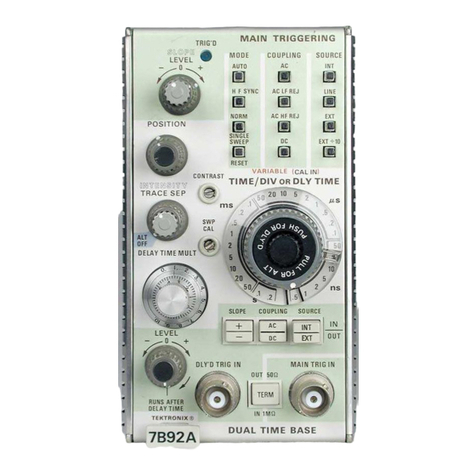
Tektronix 7B92A User manual

°
Tektronix,
Inc
.
P.O
.
Box
500
Beaverton,
Oregon
97077
COMMITl"ED
TO
EXCELLENCE
RLSASS
~HE
K
F'4R
HANGS
IN~~R
ATION
AT
THE
REAR
~~'
THIS
MANUAL
.
I
N
TF~
U
~T
I
Q
N
M
loJ,~
L
Serial
Number
__ ._
070-1751-02
First
Printing
JUN
1978
Product
Group
42
Revised
JUN
1987

LIST
OF
ILLUSTRATIONS
............
,..
iii
SAFETY
SUMMARY
.
. .
..................................
.
v
Page
SECTION
1
OPERATING
INSTRUCTIONS
INTRODUCTION
..........................
......
. .
.
. .
.
. .
1-1
INSTALLATION
........................ .
.
......
....
....
1-1
FRONT-PANEL
CONTROLS,
CONNECTORS,
AND
INDICATORS
.....
1-2
Main
Triggering
Controls
......................,.....,,,
,
1-2
Sweep
Controls
.
. .
.
..............................,,,.
,
1-4
Delayed
Triggering
Controls
..........................,,
1-5
Front-Panel
I
nputs
..........................,,.,,,,,,
, ,
1-5
FUNCTIONAL
CHECK
.............................,..
.
.
. .
1-5
Setup
Procedure
.........................
....
,
1-6
Sweep
Functions
.........................
,
1-6
Triggering
Functions
......................
......
...
..,
,
1-7
GENERAL
OPERATING
INFORMATION
..........
. .
.
...
. .
...
. .
1-8
Main
Triggering
.........................
...
.
. .
.
.....
. .
1-8
Main
Trigger
Modes
.....................
.
.
.
. .
......
,,.,
1-8
Main
Trigger
Coupling
..............,...
.
.
.
,.,.
,
1-9
Main
Trigger
Source
...................
...
.
,
...
1-10
Input
Impedance
......................
...
....
....
.
. ,
1-10
Trigger
Slope
.......................
...
.......
. .
.....
1-10
Trigger
Level
.......................
...
......
....
.....
1-10
Selecting
Sweep
Rates
................
. .
............,,,.
1-12
TimeMeasurement
..................
.
.
.,.
...
1-12
Display
Modes
.................
. .
.
.
..................
1-12
Delay
Time
Multiplier
.........
. .
.
...
........,.
1-13
Delayed
Sweep
Triggering
.
....
.....
.
.
...........,,,,,.,,
1-13
SECTION
2
SPECIFICATION
........
...
...........,..
, .
.
2-1
WARNING
THE
FOLLOWING
SERVICING
INSTRUCTIONS
AREFOR
USE
BY
QUALIFIED
PER-
SONNEL
ONLY
.
T
O
AVOID
PERSONAL
INJURY,
DO
NOT
PERFORM
ANY
SERVICING
OTHER
THAN
THAT
CONTAINED
IN
OPERATING
INSTRUCTIONS
UNLESS
YOUARE
QUALIFIED
TO
DOSO
.
SECTION
3
THEORY
OF
OPERATION
Block
Diagram
Description
................
.......,..,,,,.
. .
3-1
Detailed
Circuit
Description
..............
................
, ,
3-1
Main
Trigger
Generator
...............
...............
,,,
3-1
Delaying
Sweep
Generator
.............
.......
. .
.....
....
3-3
Delayed
Trigger
Generator
.............
.......
. .
.,,,,
.,.
3-4
Delayed
Sweep
Generator
............
........
, .
,,,,.
.,,,
3-6
Horizontal
Logic
.................
.
.
.....
.
. .
. .
.....
...,
3-6
Output
Amplifier
................
. .
.
....
.
.
....
....
.....
3-7
Readout
.
.
.
. .
.........................
..............
3-7
SECTION
4
MAINTENANCE
Page
Preventive
Maintenance
..................
.............
....
4-1
Cleaning
. .
.
........................
.............
.
.
. .
4-1
Visual
Inspection
......................
............
....
4-1
Lubrication
.
.
.
.
......................
..............
. .
4-1
Semiconductor
Checks
.................
.............
...
4-2
Adjustment
After
Repair
.................
.............
...
4-2
Troubleshooting
.
.
......................
.............
...
4-3
Troubleshooting
Aids
...................
.............
...
4-3
Troubleshooting
Equipment
..............
.............
...
4-6
Troubleshooting
Techniques
..............
.............
. .
4-6
Corrective
Maintenance
....................
........
.
....
. .
4-8
Obtaining
Replacement
Parts
..............
.............
. .
4-8
Soldering
Techniques
...................
..............
.
4-8
Component
Removal
and
Replacement
.......
..............
.
4-9
Adjustment
After
Repair
..................
.......
.
......
.
4-11
Repackaging
For
Shipment
...............
....
.
.........
.
4-11
SECTION
5
PERFORMANCE
CHECK/CALIBRATION
Preliminary Information
...
.
.................
.
.
.
. .
. .
.
....
5-1
Test
Equipment
Required
.
...
....................
. .
. .
....
5-1
Part
I
Performance
Check
. .
...
.....................
.
.
.....
5-4
Outline
for
Part
I
Performance
Check
..................
.....
5-6
A
.
Trigger
Sensitivity
.
.....
...
.
...................
....
5-4
B
.
Horizontal
System
.
....
.........................
...
5-4
Preliminary
Procedure
.......
...
.
....................
...
5-4
A
.
Trigger
Sensitivity
.
.......
........................
...
5-5
B
.
Horizontal
System
.
. .
.
....
.
.
......................
...
5-10
Part
II
Calibration
.......
.
....
.
.
.
.
...................
....
5-16
Outline
for
Part
II
Calibration
. .
. .
.
.
. .
.................
....
5-16
A
.
Trigger
Sensitivity
(SN
8070000-above)
...............
...
5-16
B
.
Trigger
Sensitivity
(SN
~069999-below)
................
. .
5-16
C
.
Horizontal
System
.
...........
...................
. .
5-17
Preliminary
Procedure
.
..........
...................
. .
5-17
A
.
Trigger
Sensitivity
(SN
~070000-above)
.
.
.................
.
5-18
B
.
Trigger
Sensitivity
(SN
~069999-below)
.
.
.................
.
5-25
C
.
Horizontal
System
................
..................
.
5-33
SECTION
6
OPTIONS
SECTION
7
REPLACEABLE
ELECTRICAL
PARTS
SECTION
8
DIAGRAMS
AND
CIRCUIT
BOARD
ILLUSTRATIONS
SECTION
9
REPLACEABLE
MECHANICAL
PARTS
Change
Information
TS
(coot)

REV
APR
1984
L
.I
~°
Figure
No
.
Page
Frontispiece
7B92A
Dual
Time
Base
1-1
Location
of
Variable
and
Mainframe
Selector
multi-pin
connectors
.
......
1-1
1-2
Location
of
release
latch
. . . . . . . .
.
. .
..........................
1-2
1-3
Front-panel
controls
and
connectors
.
...........................
1-3
1-4
Effect
of
MAIN
TRIGGERING
LEVEL
and
SLOPE
controls
on
crt
display
. . .
1-11
1-5
Area
of
graticule
used
for
most
accurate time
measurements
.
..........
1-12
1-6
Typical
alternate
sweep
display
.
. .
.
.
...........................
1-13
2-1
Dimensional
drawing
.
........
.
.
.
...........................
2-5
4-1
Lubrication
procedure
for
a
typical
cam
switch
.
....................
4-2
4-2
Semiconductor
lead
configurations
.
.
.
.
........................
.
4-4
4-3
Inter-board
multi-pin
connector
assembly
. .......................
.
4-5
4-4
End-lead
multi-pin
connector
assembly
.
........................
.
4-5
4-5
Location
of
pin
numbers
of
Interface
connector
.
..................
.
4-5
5-1
Main
Triggering
level
range
. . ................................
.
5-6
5-2
Delayed
Triggering
level
range
.
..............................
.
5-6
5-3
Variable
Time/Division
range
. .................................
5-13
5-4
Fast
delay time
accuracy
. . ...............................
.
. .
.
5-14
5-4A
AC
HF
REJ
Balance
.........
.
.
.
...................
.....
........ ....
5-19
5-5
DC
balance
.
(Circle
denotes
correct
trigger
point
.)
..................
5-19
5-6
Trigger
Sensitivity
.
(Circle
denotes
correct
trigger
point
.)
.............
5-19
5-7
Main
Triggering
level
range
.
(Circle
denotes
triggering
limits
.)
.........
5-19
5-8
Delayed
Triggering
level
range
.
(Circle
denotes
triggering
limits
.)
.......
5-21
5-9
DC
balance
.
(Circle
denotes
correct
trigger
point
.)
...
...............
5-26
5-10
Trigger
sensitivity
.
(Circle
denotes
correct
trigger
point
.)
.............
5-26
5-11
Main
Triggering
level
range
.
(Circle
denotes
triggering
limits
.)
.........
5-27
5-12
Delayed
Triggering
level
range
.
(Circle
denotes
triggering
limits
.)
.......
5-29
5-13
Correct
DTM
Scale
and
Delay
Start
adjustment
(circle)
.
..............
5-34
5-14
Variable
Time/Division
range
. .................
................
5-38
5-15
Fast
delay time
accuracy
. ....................
................
5-39

7B92A
Figure
No
.
LIST
OF
ILLUSTRATIONS
(cont)
The
illustrations
in
Section
8 are
located
near
their
associated
diagrams
on
the
foldout
pages
.
8-1
Circuit
board
locations
8-2
Block
diagram
8-3
A3
Coupling
Switch
circuit
board
8-4
A5
Delayed
Triggering
Switch
circuit
board
8-5
A2
Source
Switch
circuit
board
8-6
A4
Mode
Switch
circuit
board
8-7
A1
External
Input
circuit
board
8-8
A8
Main
Trigger
circuit
board
(SN
8070000-above)
8-9
A8
Main
Trigger
circuit
board
(SN
8069999-below)
8-10
A9
Delayed
Trigger
circuit
board
(SN
B096951-above)
8-11
A9
Delayed
Trigger
circuit
board
(SN 870000-B096950)
8-12
A9
Delayed
Trigger
circuit
board
(SN
8069999-below)
8-13
A6
Interface
circuit
board
(SN
B095741-above)
8-14
A6
Interface
circuit
board
(SN
8095740-below)
8-15
A7
Logic
circuit
board
(SN
8059999-below)
8-16
A7
Logic
circuit
board
(SN
8060000-above)
8-17
A12
Readout
circuit
board
8-18
Location
of
Sweep
Timing
adjustments
8-19
Location
of
Main
Trigger
adjustments
(SN
8069999-below)
8-20
Location
of
Delayed
Trigger
adjustments
(SN
8069999-below)
8-21
Location
of
Main
Trigger
adjustments
(SN
B070000-above)
8-22
Location
of
Delayed
Trigger
adjustments
(SN
8070000-above)

This
manual
contains
safety
information
that
the
user
must
follow
to
ensure
safe
operation
of
this
instrument
.
WARNING
information
is
intended
to
protect
the
operator
;
CAUTION
information
is
intended
to
protect
the instrument
.
The
following
are
general
safety
precautions
that
must
be
observed
during
all
phases
of
operation
and
maintenance
.
Ground
the
Instrument
To
reduce
electrical-shock
hazard,
the
mainframe
(oscilloscope)
chassis
must
be properly
grounded
.
Refer
to
the
mainframe
manual
for
grounding
information
.
Do
Not
Operate
in
Explosive
Atmosphere
Do
not operate
this
instrument
in
an area
where
flammable
gases
or
fumes
are
present
.
Such
operation
couldcause
an
explosion
.
Avoid
Live Circuits
Electrical-shock
hazards
are
present
in
this
instrument
.
The
protective
instrument
covers
must
not
be
removed
by
operating
personnel
.
Component
replacement
and
infernal
adjustments
must
be
referred
to
qualified
service
personnel
.
Do
Not
Service
orAdjust
Alone
Do
not
service
or
make
internal
adjustments
to this
instrument
unless
another
person,
capable
of
giving
first
aid
and
resuscitation,
is
present
.
Warning
Statements
Warning
statements
accompany
potentially
dangerous
procedures
in
this
manual
.
The
following
warnings
appear
in
this
manual and
are
listed
here
for
additional
emphasis
.
To
avoid
electrical
shock,
disconnect
theinstrument from
the
power
source
before
soldering
.
To
avoid
electrical
shock,
disconnect
the
instrument
from
the
power
source
before
replacing
components
.
Handle
silicone
grease
with care
.
Avoid
getting
silicone
grease
in
eyes
.
Wash
hands
thoroughly
after
use
.

7B92A
TR16'0
EEODE
COUPIIRG
SOURCE
e
f
RuTO
~c
IxT
a
w i
aYltc
Rc
EE
REJ
urE
TORY
RC
RE
REJ
FXT
POSITION
RRFi
v
-
'
~
CAL
IN'~
c
.uwrlYSr
TIME/DIV
OR
DLY
TIME
OF'SUP
.'i`
TRACE
SEP
.
~
5U ZD
10
h,~
-
IJf
~
ms
awo
.6
/~"
v
y
~
.2
n
h
1~
~ o
OlYO
TRIG 1~
YAill
TRt61R
OOr
WO
~,~~
.~
.~
~~
II
.~
fl~i
Aif
ER
T E
R
M
OEIAYTYRE
:~
reKrROnaf
~-
DUAL
TIME
BASE
7B92A

OPERATING
INSTRUCTIONS
INTRODUCTION
INSTALLATION
The
7B92A
Dual
Time Base
unit
provides
normal,
The
7B92A
is
designed
to
operate
in
the
horizontal
delayed,
intensified,
and
alternate
sweep
operation
for
plug-in
compartment
of
the
oscilloscope
.
This
instrument
TEKTRONIX
7000-Series
Oscilloscopes
.
Calibrated
can
also
be
installed
in
a
vertical
plug-in
compartment
to
sweep
rates
from
0
.2
second
to
0
.5
nanosecond
and
provide a
vertical
sweep
on
the
crt
.
However,
when
used
in
triggering
to
500
megahertz
are provided
.
The
7B92A
is
this
manner,
there
are
no
internal
triggering
or
retrace
intended
for
use
with
high-frequency
7000-Series
blanking
provisions,
and
the
unit
may
not
meet
the
Oscilloscope
systems
;
however,
most
7B92A
functions
specifications
given
in
the
Specification
section
of
this
are
compatible
with
all
7000-Series Oscilloscopes
.
manual
.
Other
features
include
lighted
pushbutton
switches,
Before
proceeding
with
installation,
check
the
settings
compatibility
with
indicator
oscilloscopes
having
an
of
the
Time/Div
Variable
Selectormulti-pin
connector
and
alphanumeric
readout
system,
and
0
to
9
.8
times
con-
the
Mainframe
Selector
multi-pin
connector
(see
Fig
.
1-1
)
.
tinuous
sweep
delay
.
A
VARIABLE
control
allows
con-
The
Time/Div
Variable Selector
determines
whether
the
tinuously
variable
sweep
rates
between
calibrated
steps
.
front-panel
Time/Div
VARIABLE
control
operates
in
con-
Also,
when
operating
in
the
AUTO
MAIN
TRIGGERING
junction with
the
delaying
or
delayed
sweeps
.
The
Main-
Mode,
a
bright
base
line
is
displayed
in
the
absence
of
a
frame
Selector
adapts the
7B92A
to
the
oscilloscope
trigger
signal
.
mainframe
being
used
.
The
two
mainframe
selections
are
:
This
section
describes the
operation
of
the
front-panel
controls
and
connectors,
and
provides a
functional
check
and
general operating
information
for
this
instrument
.
REV
B,
JUN
1978
NOTE
The
ALT
OFF
position,
which
allows
fhe
lnfensified
mode
of
operation,
is
applicable
to
instruments
SN
8060000-ab
o
ve
.
1
.
7800
and
7900-Series
Oscilloscopes
.
2
.
All
other
7000-Series Oscilloscopes
.
NO
TE
The
7871
will
not
delay
the
7892A
for
displaying
alternating
Delaying
and
Delayed
sweeps
.
lnsfead,
it
causes
a
sweep
lock-up
to
occurunder
the
following
conditions
;
with
the
7871
in
the
A
horizontal
com-
Fig
.
1-1
.
Location
of
Variable
and
Mainframe
Selector
multi-pin
connectors
.
Section
1-7B92A
i~s2-oz

Operating
Instructions-7B92A
To
install
the
7B92A
in
a
plug-in
compartment,
push
it
in until
it
fits
firmly
into
the
compartment
.
The
front
panel
of
the
7B92A
should
be
flush
with
the
front
panel
of
the
oscilloscope
.
Eventhough
the gain
of
the
oscilloscope
is
standardized,
the
sweep
calibration
of
the
7B92A
should
be
checked
when
installed
.
The
procedure
for
checking
the
unit
is
given
under
Sweep
Calibration
in
the
Operating
Checkout
procedure
in
this
section
.
To
remove
the
7B92A,
pull
the
release latch
(see
Fig
.
1-2)
to
disengagethe
unit
from
the
oscilloscope,
and
pull
it
out
of
the
plug-in
compartment
.
partmentandthe7B92AintheBhorizontalcompart-
shows
the
Time/Div
Variable
and
Mainframe
Selectors
.
meni, the
sweep
locks
up
if
the
7B92A
is
in
its
Fig
.
1-3
shows
the
front-panel
controls,
connectors,
and
Alternate
mode
and
the
Mainframe
Horizontal
mode
i
ndicators
.
i
s
Alf
.
Lock-up
can
be
avoided
by
changing
the
Mainframe
Horizontal
mode
to
Chop
or
B
.
This
allows
both
7B92A
sweeps
to
be displayed
.
RELEASE
LATCH
t
X52-t
s
Fig
.
1-2
.
Location
of
release
latch
.
MAIN
TRIGGERING
Controls
LEVEL
Control
Selects
amplitude
point
on
trigger
signal
where
sweep
triggering
occurs
when
the
MAIN
TRIGGERING
MODE
AUTO,
NORM,
or
SINGLE
SWEEP
switches are pressed
.
When
the
MAIN
TRIGGERING
MODE
HF
SYNC
switch
is
pressed,
the
LEVEL
control adjusts
the
frequency
of
the
trigger
generator
to
synchronize
with
the
frequency
(or
sub-harmonic)
of
the
triggering signal to
provide
a
stable
display
.
SLOPE
Control
Permits
triggering
on
the
positive
or
negative
slope
of
the
trigger
signal
(except
in
HF
SYNC)
.
O
TRIG'D
Indicator
When
lit,
indicates
that
the
sweep
is
triggered
and
will
produce
a
display
with
correct
setting
of
the
POSITION
control
and
the
controls
on
the
associated
amplifier
plug-in
units)
and
os-
cilloscope
.
MODE
Switches
Select
the
desired
MAIN
TRIGGERING
mode
.
Selected
mode
is
indicated
by
lighted
pushbutton
.
AUTO
:
Selects
a
triggered
sweep
initiated
by the
applied
trigger
signal
at
a
point
determined
by the
LEVEL
control
and
SLOPE
control
when
the
trigger
signal
repetition
rate
is
above30
hertz
and
within
the
frequency
range
selected
by
the
COUPLING
switches
.
When
the
LEVEL
control
is
outside
the
amplitude
range,
the
trigger
repetition
rate
is
outside
the
frequency
range
selected
by the
COUPLING
switches,
or
the
trigger
signal
is
inadequate,
the
sweep
free-runs
to
provide a
reference
trace
.
FRONT-PANEL
CONTROLS,
CONNECTORS,
AND
INDICATORS
HFSYNC
:
sweep
initiated
by
trigger
signals
with
repetition
rates
above
100
megahertz
and
within
the
All
controls,
connectors,
and
indicators
required
forthe
range
selected
by
the
COUPLING
switch
.
Stable
operation
of
the
7B92A,
except
the
Time/Div
Variable
and
display
can
be obtained
when
the
LEVEL
control
Mainframe
Selectors,
are
located
on
the
front
panel
.
A
adjusts
the
frequency
of
the
trigger
generator
to
the
brief
description
of
the
front-panel
controls,
connectors,
frequency
(or
sub-harmonic)
of
the
trigger
signal
.
and
indicators
is
given
here
.
More
detailed
information
is
When
the
LEVEL
control
is
adjusted
to
frequencies
given
under
General
Operating
Information
.
Fig
.
1-1
between
sub-harmonics,
the
sweep
free-runs
.
REV
B,
JUN
1978

REV
B,
JUN
1978
POSITION
iRIG
.D
,MAIN
TRIGGERIN
/EL
MODE
COUPLIR6
SOURCE
0
H
f
S1'~C
AC
Lf
REJ
UNf
a~ a
EIORY
AC
NF
REJ
RESET
CRRTRAST
V<'~tiaFiL~
WALIN
\
TIME/DIV
OR
DLY
TIME
tJW
~
~`~
1f
y
. '
E1J
k
i
t
OR
O~~O
.
.W
s
.e
i
~
.5
1
r"
.
RRRRCE
Fig
.
1-3
.
Front-panel
controls
and
connectors
.
_
AC
INT
IN
_
lp
DC
~`
EXT
,
OU
YT
19
u
LEVEL
.
0
DLY'D
TRIG
III
REAIII
TRIG
III
\
aUT 5SQ
.
q
\w
~
TERM
-
L
BURS
AITEII
DELATTIRIE
~
1RIG
_
TEKTRONIX®
4Y
DUAL
TIME
BASE
YY
7B92A
Operating
Instructions-7B92A
1752-17
NORM
:
Sweep
initiated
by
the
applied
trigger
signal
a
trigger
is
received
and
the
sweep
is
completed
.
The
at
a
point
selected
by the
LEVEL
control
and
SLOPE
SINGLE
SWEEP-RESET
switch
must be
pressed
control
over the
frequency
range
selected
by
the
again
before
another
sweep
can
be
displayed
.
COUPLING
switches
.
Triggered
sweep
can
be ob-
tained
only
over the
amplitude
range
of
the
applied
trigger
signal
.
When
the
LEVEL
control
is
either
outside
the
amplitude
range,
the
trigger
repetition
O
COUPLING
Switches
rate
is
outside the
frequency
range
selected
by the
COUPLING
switches,
or
the
trigger
signal
is
inade-
Select
trigger
signal
coupling
.
Selected
coupling
is
quate,
there
is
no
trace
.
indicated
by
lighted
pushbutton
.
SINGLE
SWEEP-RESET
:
When
the
SINGLE
SWEEP-RESET
switch
is
pressed,
a
single
trace
will
AC
:
Rejects
do
and
attenuates
ac
signals
below
be
presented
when
thenext
trigger
pulse
is
received
.
about
30
hertz
.
Accepts
signals
between
30
hertz
The
SINGLE
SWEEP-RESET
switch
remains
lit
until
and 500 megahertz
.

Operating
Instructions-7B92A
AC
LF
REJ
:
Rejects
do
and
attenuates
signals
below
30
kilohertz
.
Accepts
signals
between
30
kilohertz
and
500
megahertz
.
AC
HF
REJ
.
Rejects
do
and
attenuates
signals
above
50
kilohertz
.
Accepts
signals
from
30
hertz
to 50
kilohertz
.
DC
:
Accepts
all
signals
from
do
to
500
megahertz
.
V
SOURCE
Switches
Select
the
triggering
source
.
Selected
source
is
indicated
by
lighted
pushbutton
.
INT
:
°I°rigger
signal
obtained
internally
from
amplifier
plug-in
unit
of
oscilloscope
.
LINE
:
Trigger
signal
obtained
internally
from
the
line
voltage applied
to
the
oscilloscope
.
EXT
:
Trigger
signal
obtained
from
an
external
source
applied
to
the
MAINTRIG
IN
connector
.
EXT
--10
:
Trigger
signal
obtained
from
an
external
~
VARIABLE
source
applied
to
the
MAIN
TRIG
IN
connector
.
In
Tv,,o_position
switch
actuated
by
the
VARIABLE
this
position,
the
external
signal
is
attenuated
before
it
is
applied
to
the
trigger
circuit
.
control
to
select
calibrated
or
uncalibrated
sweep
rates
.
In
the
CAL
position
(knob
in)
the
VARIABLE
control
is
inoperative
and
the
sweep
rate
is
Sweep
Controls
calibrated
.
When
pressed
and
released,
the
knob
moves
out
to
activate
the
VARIABLE
control
for
uncalibrated
sweep
rates
.
The
sweep
rate
in
each
Selects
the
basic
sweep
rate
for
normal
sweep
TIME/DIV
OR
DLY
TIME
switch
position
can
be
operation
and
selects
the delay time
(multiplied
by
reduced
at
least
to
the
sweep
rate of
the
next
slower
the
DELAY
TIME
MULT
dial
setting)
when
operating
position
.
The
VARIABLE
control
will
operate
with
in
the
Alternate
or
Delayed
sweep
modes
.
The
eitherthe
delaying
or
delayed
sweep
by
means
of
the
VARIABLE
control
must
be
in
the
CAL
(knob
in)
internal
Time/Div
Variable Selector
.
position
for
calibrated
sweep
rate
.
TIME/DIV
OR
DLY
TIME
O
DLY'D
Time/Division
turned
clockwise
from
the
ALTOFF
position
.
In
this
mode,
the
delaying
sweep
is
displayed
(with
an
intensified
zone
during the time
that
the
delayed
sweep
runs)
alternately
with
the
delayed
sweep
.
Intensified
Sweep
:
The
Intensified
mode,
a
function
of
the
delaying
and
delayed
sweeps
is
selected
when
the
DLY'D
Time/Division
switch
is
pulled
out
and
rotated
clockwise,
and
the
TRACE
SEP
control
is
rotated
fully
counterclockwise
to
the
ALTOFF
position
(see
Fig
.
1-3)
.
In
this
mode,
a
portion
of
the
delaying
sweep
is
intensified
during thetime
that
the
delayed
sweep
generator runs
.
DLY'D
Sweep
:
The
Delayed
sweep
mode
is
selected
when
the
DLY'D
Time/Division
switch
is
pulled
out,
rotated
for
the
desired
delayed
sweep
rate,
and
then
pushed
in
.
In
this
mode,
the
delayed
sweep
is
displayed
at
a
rate
determined
by
the
DLY'D
Time/Division
switch
at
the
end
of
each
delay
period,
as
selected
by the
TIME/DIV
OR
DLY
°i°IME
switch
and
the
DELAY
TIME
MULT
dial
setting
.
10
POSITION
Control
Selects
the
delayed
sweep
rate
for
operation
in
Positions
the
display
horizontally
on
the
graticule
.
Delayed
and
Alternate
sweep
modes
.
The
VARIABLE
control
must
be
in
the
CAL
(knob
in)
position
for
calibrated
sweep
rate
.
11
CONTRAST
Adjustment
Four
display
modes
can
be
selected
by the
following
Varies
the
relative
brightness
of
the
intensified
switch
settings
:
portion
of
the delaying
trace
when
in
the
Alternate
Normal
Sweep
:
A
normal
sweep
is
selected
when
the
mode
.
TIME/DIV
OR
DLY
TIME
switch
and
the
DLY'D
Time/Division switches are locked together
at
the
same
sweep
rate
.
The
DLY'D
Time/Division
knob
12
TRACE
SEP/ALT
OFF
Control
must
be
pressed
in
for
normal
sweep
mode
.
Calibrated
sweep
rates
from
0
.2
second/division
to
This
control
vertically
positions
the
delaying
sweep
0
.5
nanosecond/division
can
be
selected
display
up
to
3
.5
divisions
above
the
delayed
sweep
display
when
in
the
Alternate
mode
.
The
ALT
OFF
ALT
Sweep
:
The
Alternate
mode
is
selected
when
position
allows
the
Intensified
sweep
mode
of
the
DLY'D
Time/Division
switch
is
pulled
out
and
operation,
permitting
the
display
of
an
intensified
rotated
clockwise
and
the
TRACE
SEP
control
is
portion
of
the delaying
sweep
.
REV
B,
JUN
1978

13
INTENSITY
Control
Varies
the
intensity
of
the
Intensified
sweep
only
;
when
operating
in
the
Intensified
or
Alternate
mode
(must be
set
near
clockwise
end
when7B92A
is
operating
in
some
7000-Series
Oscilloscopes)
.
~4
SWP
CAL
Adjustment
~g
COUPLING
Switch
Screwdriver
adjustment
sets
the
basic
timing
of
the
7B92A
to
compensate
for
slight
differences
in
input
Two-position
pushbutton
switch
to
determine
the
sensitivity
when
changing
indicator
oscilloscopes
.
method
of
coupling the
trigger
signal to
the
delayed
trigger
circuit
.
DELAY
TIME
MULT
Dial
Provides
variable
delay
of
0
to
9
.8
times
the
basic
delay time
selected
by
the
TIME/DIV
OR
DLY
TIME
switch
.
Delayed
TriggeringControls
Front-Panel
Inputs
SLOPE
Switch
Two-position
pushbutton
switch
to select
the slope
of
the
trigger
signal
which
starts
the
delayed
sweep
.
Operating
Instructions-7B92A
IN~T
:
The
delayed
trigger
signal
is
obtained
from
the
vertical
amplifier
of
the
oscilloscope
.
EXT
:
The
delayed
trigger
signal
is
obtained
from
an
external
source
connected
to
the
DLY'D
TRIG
IN
connector
.
AC
:
Rejects
do
and
attenautes
signals
below
30
hertz
.
Accepts
trigger
signals
from
30
hertz
to
500
megahertz
.
DC
:
Accepts
trigger
signals
from
do
to
500
megahertz
.
16
LEVEL
Control
20
MAIN
TRIG
IN
Connector
Determines
the
delayed
trigger
mode
and
the
Serves as
an
external
trigger
input
for
the
main
delayed
trigger
level
.
triggering
circuit
when
the
MAIN
TRIGGERING
SOURCE
EXT
or
EXT
~
10
pushbutton
switches
are
RUNS
AFTERDELAY
TIME
(LEVEL
control
turned
pressed
.
fully
clockwise
into
detent)
:
Delayed
sweep
runs
immediately
following
the
delaytimeselected
bythe
TIME/DIV
OR
DLY
TIME
switch
and
the
DELAY
21
TERM
Switch
TIME
MUL
-
f
dial
.
Delayed
Slope,
Coupling,
and
Source
functions are
inoperative
.
Two-Position
pushbutton
switch
to
select
50
ohms
(out
position)
or
1
megohm
(in
position)
input
Delayed
Sweep
Triggerable
:
When
the
Delayed
impedance
for
the
MAINTRIG
IN
and
DLY'D
TRIG
Triggering
LEVEL
control
is
turned
IN
connectors
.
counterclockwise
out
of
detent,
the
delayed
sweep
is
Trggerable
.
The
Delayed
Triggering
LEVEL
con-
trol
can
now
be
rotated
to
select
the
amplitude
point
DLY'D
TRIG
IN
Connector
on the
trigger
signal
at
which
the
delayed
sweep
is
Serves
as
an
external
trigger
input
for
the
delayed
triggered
.
In
the
Delayed
Sweep
Triggerable
mode,
triggering
circuit
when
the
Delayed
Triggering
the
delayed
Slope,
Coupling,
and
Source
functions
SOURCE
switch
is
set
to
EXT
.
are
activated
.
CAUTION
Do
notexceed
7
volts
(rms)
of
external
signal
when
50
O
termination
is
selected
.
+
:
The
delayed
sweep
can
be
triggered
on
the
positive
slope
of
the
trigger
signal
.
FLINCTICNAL
CHECK
--
:
The
delayed
sweep
can
be
triggered
on
the
The
following
procedures
may
be
used
for
familiariza-
negative
slope
of
the
trigger
signal
.
tion or as
a
check
of
basic
instrument
operation
.
The
procedure
is
divided
into
two
parts,
Sweep
Functions
and
18
SOURCE
Switch
Triggering
Functions
.
A
complete
operating
check
of
the
7B92A
functions
can
be
made
by
performing
both
parts,
or
Two-position
pushbutton
switch
to
select
the
source
each
part
may
be
performed
separately
.
If
performing the
of
the
delayed
trigger
signal
.
functional
check
procedure
reveals
a
malfunction
or
REV
A,
JUN
1978

Operating
Instructions-7B92A
possible
improper
adjustment
;
first
check
the
operation
of
the
associated
plug-in
units,
then
refer
to
the
instruction
manual
for
maintenance
and
adjustment procedures
.
NOTE
For
optimum
high-frequency
performance,
the
7B92A
should
be
installed
in
an
oscilloscope
system
with
similar
frequency
and
sweep-rate
capabilites
.
3
.
Adjust the
amplifier
plug-in
unit
volts/division
Setup
Procedure
switch
for
two
divisions
of
display
.
1
.
I
nstall
the
7B92A
i
n a
horizontal
compartment
of
the
oscilloscope
.
2
.
Install
the
amplifier
plug-in
unit
in
a
vertical
com-
partment
.
3
.
Turn on
the
oscilloscope
and
allow
at
least
20
minutes
warm
up
.
6
.
Check
the
crt
display
for
one
complete
cycle
per
division-
If
necessary,
adjust
the
SWP
CAL
screwdriver
4
.
Set the
7B92A
controls
as
follows
:
adjustment
for
one
complete
cycle per
division
over
the
center
eight graticule divisions
.
Be
sure
that
the
timing
of
MAIN
°TRIGGERING
the
calibrator signal
is
accurate
within
0
.5%
.
SLOPE
(-+)
MODE
AUTO
COUPLING
AC
SOURCE
INT
Delayed
Triggering
LEVEL
RUNS
AFTER
DELAY
TIME
SLOPE
(-§-)
COUPLING AC
SOURCE
INT'
Sweep
Controls
Sweep
Functions
Normal
Sweep
.
Perform
the
following
procedure
to
obtain
a
normal
sweep
and
demonstrate
the
function
of
the
related
sweep
controls
:
1
.
Perform
the
Setup
Procedure
.
2
.
Connect
a 4
volt,
one-kilohertz
signal
from
the
oscilloscope
calibrator to
the
amplifier
plug-in
unit
input
.
4
.
Rotate the
MAIN
TRIGGERING
LEVEL
control
fora
stable
display
.
5
.
Rotatethe
POSITIONcontrolandnotethatthetrace
moves
horizontally
.
Alternate
and
Delayed
Sweep
.
Perform
the
following
procedure
to
obtain
alternate-delayed
sweeps
and
demonstrate
the
function
of
the
related
sweep
controls
:
7
.
Pull
out the
DLY'D
Time/Division
knob
and
rotate
clockwise
to
0
.1
ms
for
the
Alternate
sweep
mode
.
Note
both an
intensified
trace
and
a
normal-intensity
delayed
sweep
trace
on
the
crt
.
Increased
oscilloscope
intensity
may
be
required
for
viewing the delayed
sweep
.
POSITION
Midrange
8
.
Rotate
theINTENSITYcontrolandnotethatitvaries
INTENSITY
As
desired
the
intensity
of
the
delaying
sweep
.
TIME/DIV
OR
1
ms
DLY
TIME
DLY'D
Time/Division
1
ms
(knob
in)
9
.
Rotate the
CONTRAST
adjustment
for
adequate
VARIABLE
CAL
identification
on
the
intensified
portion
of
the
delaying
sweep
when
alternating
with
Delayed
sweep
.
Time/Div
Variable
Delayed
Sweep
Selector
(internal)
DELAY
TIME
MULT
1
.00
TRACE
SEP
Midrange
NOTE
5
.
Set the
oscilloscope
to
display
the
plug-in
units
and
When
operating
in
the
Intensified
mode,
the
inten-
adjust
for
a
well-defined
display
.
See
oscilloscope
and
sified
zone
is
controlled
by the
intensity
of
the
test
amplifier
plug-in
unit
instruction
manuals
for
detailed
oscilloscope
instead
of
the
7B92A
CONTRAST
and
operating
instructions
.
INTENSITY
controls
.
REV
B,
JUN
1978

10
.
Rotate the
TRACE
SEP
control
to
vertically
posi-
and DC,
for
both the
positive
and
negative
positions
of
the
tion
the
delaying
sweep
trace
with
respect
to
the
delayed
SLOPE
control
(MAIN
TRIGGERING
LEVEL
control
may
sweep
trace
.
With
the
TRACE
SEP
control
in
the
ALT
OFF
be
adjusted
as
necessary
for
a
stable
display)
.
position,
only
the
Intensified
sweep
will
be displayed
.
18
.
Change
the
MAIN
TRIGGERING
SOURCE
switch
11
.
Rotate
the
DELAY
TIME
MULT
dial
and
note
that
toEXT---10
.Settheoscilloscopecalibratorforfourvoltsat
the
amount
of
delay
time
before
the
intensified
portion
of
one
kilohertz
and
adjust
the
amplifier
plug-in
unit
volts/div
the
display
is
controlled
by
the
DELAY
TIME
MULT
dial
.
switch
for
about
four
divisions
of
display
.
Check
that
a
stable
display
can
be obtained
with
the
MAIN
TRIGGERING
COUPLING
switch
set
to
AC,
AC
HF
REJ,
12
.
Press the
DLY'D
Time/Division
switch
in
for
the
andDC,
for
both the
positive
and
negative
positions
of
the
Delayed
sweep
mode
.
Note
the
delayed
display
with
SLOPE
control
(MAIN
TRIGGERING
LEVEL
control
may
sweep
rate
determined
by
the
DLY'D
Time/Division
be
adjusted
as
necessary
to
obtain
a
stable display)
.
switch
.
Remove
all
connections
from
the
oscilloscope
system
.
13
.
Press
and
release
the
VARIABLE
control
.
Rotate
19
.
Set the
MAIN
TRIGGERING
COUPLING
switch
to
the
VARIABLE
control
and
note
that
the
sweep
rate
AC
and
SOURCE
switch
to
INT
.
Connect
a
one-kilohertz
indicated
by
theDLY'DTime/Division
switch
can
be
varied
calibrator signal
from
the
oscilloscope
to
the
amplifier
to
at
least
the
sweep
rate of
the next adjacent
position
plug-in
unit
input
and
adjust for
about
four
divisions
of
(0 .2
ms)
.
The
internal
Time/Div
Variable Selector
must
be
display
amplitude
.
Adjust
the
MAIN
TRIGGERING
LEVEL
set
to
the
Delayed
Sweep
position
.
Return
the
VARIABLE
control
for
a
stable
display
.
Setthe
MODE
switch
to
NORM
control
to
the
CAL
position
(knob
in)
.
and
check
for
a
stable
display
.
Change
the
MODE
switch
to
AUTO
and
adjust
the
LEVEL
control
for
afree-running
display
.
Change
the
MODE
switch
to
NORM
and
checkfor
Triggering
Functions
no
display
.
Main
and
Delayed
Triggering
.
Perform
the
following
procedure
to
obtain
a
triggered
alternate,
normal,
or
20
.
Adjust the
MAIN
TRIGGERING
LEVEL
control
for
delayed
sweep
and
demonstrate
the
function
of
the
a
stable
display
.
Change
the
MAIN
TRIGGERING
MODE
related
controls
:
switch
to
SINGLE
SWEEP
.
Press the
RESET
button
and
14
.
Perform
the
Setup
Procedure
.
Connect
the
one-
check
for
one
sweep
as the
RESET
button
is
pressed
.
kilohertz
calibrator
signal
from
the
oscilloscope
to
the
Removetheone-kilohertzsignalfromtheamplifierplug-in
amplifier
plug-in
unit
input
and
adjust for
about
four
unit
and
press
the
RESET
button
.Checkfornodisplayand
divisions
of
vertical
display
.
RESET
button
light
on
.
Connect
the
one-kilohertz
signal
to
the
amplifier
plug-in
unit
input
and
check
for
one
sweep
as the
signal
is
applied
.
Remove
all
connections
from
the
15
.
Set
the
DLY'D
Time/Division
switch
and
the
oscilloscope
system
.
TIME/DIV
OR
DLY
TIME
switch
to
1
ms,
and
press
in
the
DLY'D
Time/Division
knob
(normal
sweep
mode)
.
Rotate
the
MAIN
TRIGGERING
LEVEL
control
for
a
stable
21
.
Set the
MAIN
TRIGGERING
MODE
switch
to
display
.
AUTO
and
SOURCE
switch
to
AC
.
Turn
the
Delayed
Triggering
LEVEL
control
fully
clockwise
to
the
RUNS
AFTER
DELAY
TIME
position
.
Pull
out the
DLY'D
16
.
Check
that
a
stable
display
can
be obtained
with
Time/Division
switch
and
rotate to
0
.2
ms
(Alternate
the
MAIN
TRIGGERING
COUPLING
switch
set
toAC,
AC
mode)
.
Connect
a 0
.4 volt,
one-kilohertz
signal
from
the
HF
REJ,
and
DC,
for
both the
positive
and
negative
oscilloscope
calibrator to
the
amplifier
plug-in
unit
input
positions
of
the
SLOPE
control
(MAIN
TRIGGERING
and
adjust for
about
two
divisions
of
display
amplitude
.
LEVEL
control
may
be
adjusted
as
necessary
to
obtain
a
Rotate the
MAIN
TRIGGERING
LEVELcontrolforastable
stable display)
.
Remove
all
connections
from the os-
intensified
display
.
The
INTENSITY
control
may
need
to
cilloscope
system
.
be
adjusted
to
view the
intensified
display
.
Rotate the
DELAY
TIME
MULT
dial
and
note
that
the delay time
before
the
intensified
portion
of
display
is
continuously
17
.
Connect
a
0
.4
volt,
one-kilohertz
signal
from
the
variable
.
oscilloscope
calibrator to
the
amplifier
plug-in
unit
and
to
the
MAINTRIG
IN
connector
.
Setthe
MAIN
TRIGGERING
SOURCE
switch
to
EXT
.
Set
the
amplifier
plug-in
unit
22
.
Set the
Delayed
Triggering
SLOPE,
COUPLING,
volts/div
switch
for
about
four
divisions
of
display
.
Check
and
SOURCE
switches
to
(+),
AC,
and INT
.
Rotate
the
that
a
stable
display
can
be obtained
with
the
MAIN
pelayed
Triggering
LEVEL
control
counterclockwise
out
TRIGGERING
COUPLING
switch
set
to
AC,
AC
HF
REJ,
of
the
detent
and
adjust for
a
stable
display
.
Rotate
the
REV
A,
JUN
1978
Operating
Instructions--7B92A

Operating
Instructions--7i392A
DELAY
TIME
MULT
dial
and
note
that
the
intensified
stable
display
.
Check
that
stable
crt
displays
can
be
sweep
does
not
start
at
the
completion
of
the delay time
obtained
with
the
Delayed
Triggering
COUPLING
switch
but
waits
for
the
next
trigger
pulse
.
set
to
AC
and
DC
.
Disconnect
the
high-frequency
signal
from the
oscilloscope
system
.
23
.
Check
that
a
stable
display
can
be obtained
with
the
Delayed
Triggering
COUPLING
switch
set
to
AC
and
Ca
NERAI~
®IP
RATING
INF~I~MA°TION
DC
for
both the
(-f-)
and
(---)
positions
of
the
SLOPE
switch
(Delayed
Triggering
LEVEL
control
may
be
adjusted
as
MAIN
TRIGGERING
necessary
for
a
stable
display)
.
The
MAIN
TRIGGERINGMODE,
COUPLING,
and
SOURCE
pushbutton
switches are
arranged
in
a
se
24
.
Change
the
Delayed
Triggering
SOURCE
switch
quence
which
places
the most-often
used
position
at
the
top
of
each
series
of
pushbuttons
.
With
this
arrangement,
to
EXT
.
Connect
a
0
.4
volt,
one-kilohertz
signal
from
the
a
stable
display
can
usually
be
obtained
by
pressing
the
oscilloscope
calibrator to
the
DLY'D
TRIG
IN
connector
.
top
pushbuttons
:
AUTO,
AC,andINT
.
When
an
adequate
Check
that
a
stable
display
can
be obtained
with
the
trigger
signal
is
applied
and
the
LEVEL
control
is
set
Delayed
Triggering
COUPLING
switch
set
to
AC
andDC,
correctly,
the
TRIG'D
indicator
will
light
.
If
the
TRIG'D
for
both the
(+-)
and
(-)
positions
of
the
SLOPE
switch
indicator
is
not
lit
:
(1)
the
LEVEL
control
is at
a
setting
(Delayed
Triggering
LEVEL
control
may
be
adjusted
as
outside
the
range
of
the
trigger
signal
from
the
amplifier
necessary
for
a
stable
delayed
sweep
display)
.
plug-in
unit,
(2)
the
trigger
signal
is
inadequate,
or
(3)
the
trigger-signal
frequency
is
belowthelower
frequency
limit
High-Frequency
Synchronization
.
Perform
the
follow-
of
the
COUPLING
switch
position
.
If
thedesired
display
is
ing
procedure
to
obtain
a
triggered
alternate,
normal,
or
not
obtained with these pushbuttons,
other
selections
delayed
sweep
with
a 100
megahertz
to
500
megahertz
must
be
made
.
Refer
to
the
following
discussions
or
the
input
signal
:
instruction
manuals
for
the
oscilloscope
and
amplifier
plug-in
unit
for
more
information
.
NOTE
To
check
HF
sync
operation,
a
signal
source
fre-
quency
between
100
megahertz
and500
megahertz
is
required
.
If
a
100
to
500
megahertz
signal
source
is
not
available,
or
if it
is
not
desired
to
check
the
HF
sync
operation,
the
last
two
steps
of
this
procedure
may
be
deleted
.
25
.
Change
the
MAIN
TRIGGERING
MODE
switch
to
HF
SYNC
.
Connect
a
high-frequency
signal
source
(100
to
500
megahertz)
to
the
amplifier
plug-in
unit
input
and
adjust
for
four
divisions
of
vertical
deflection
.
Adjust the
TIME/DIV
OR
DLY
TIME
switch
and
DLY'DTime/Division
switch
for
about
six
cycles
of
display
.
Rotate
the
MAIN
TRIGGERING
LEVEL
control
throughout
its
range
and
note
that
the
sweep
is
alternately
stable,
then
free-
running,
several
times
during the
rotation
(stable
display
indicates
that
the
trigger-generator
frequency
is
adjusted
to
a
sub-harmonic
of
the
trigger
signal
frequency)
.
Check
that
stable
displays
can
also
be obtained
with
the
MAIN
TRIGGERING
COUPLING
switch
set
to
AC,
AC
LF REJ,
and
DC
(MAIN
TRIGGERING
LEVEL
control
may
be
adjusted,
as
necessary,
for
a
stable
display)
.
26
.
Pull
out the
DLY'D
Time/Division
switch
and
rotate
it
to
the
next
fastest
sweep
rate
from
the
setting
of
the
TIME/DIV
OR
DLY
TIME
switch
(Alternate
mode)
.
When
the
LEVEL
control
is
in
the
detent
(RUNS
AFTER
DELAY
TIME)
the
display
should
be
stable
.
Rotate the
LEVEL
control
counterclockwise
out
of
the
detent
and
adjust
for
a
Main
Trigger
Modes
The
MODE
pushbutton
switch
selects
the
mode
in
which
the
main
sweep
is
triggered
.
AUTO
.
The
AUTO
pushbutton
provides
a
triggered
display
with
the
correct
setting
of
the
LEVEL
control
(see
Trigger
Level
discussion)
whenever
an
adequate
trigger
signal
is
applied
.
The
TRIG'D
indicator
lights
when
the
display
is
triggered
.
When
the
trigger
repetition
rate
is
outside
thefrequen-
cy
range
selected
by the
COUPLING
switch
or
the
trigger
signal
i
s
i
nadeq
uate,
the
sweep
free-runs
at
the
sweep
rate
indicated
by the
TIME/DIV
OR
DLY
TIME
switch
(TRIG'D
indicator
off)
.
An
adequate
trigger
signal
ends
the
free-
running
condition
and
a
triggered
display
is
presented
.
When
the
LEVEL
control
is
at
a
setting
outside
the
amplitude
range
of
the
trigger
signal,
the
sweep
also
free
runs
at
the
sweep
rate
indicated
by
the
TIME/DIV
OR
DLY
TIME
switch
.
This type
of
free-running
display
can
be
useful
when
it
is
desired
to
measure
only the
maximum
peak-to-peak
amplitude
of
a
signal
without observing the
waveshape
(such
as
in
bandwidthmeasurements)
.
HF
SYNC
.
The
HF
SYNC
pushbutton
permits
stable
displays
of
repetitive
signals
with
only 0
.5
division
of
internal
trigger
signal
(100
millivolts
external
signal)
required
for
frequencies
between
100
megahertz
and
500
megahertz
.
REV
C,
JUN
1978

Operating
Instructionsa--7B92A
A
triggered
display
is
obtained
when
the
LEVEL
control
When
using the
Single
Sweepmode
to
photograph
adjusts
the
frequency
of
the
trigger
generator
to
the
waveforms,
the
graticule
mustbe
photographed
separate-
frequency
or
sub-harmonic
of
the
trigger
signal
.
Stable
ly
in
the
normal
manner
to
prevent
over-exposing
thefilm
.
displays
may
be
obtained
several
times
between
the
limits
Be
sure the
camera
system
is
well
protectedagainst
stray
of
the
LEVEL
control,
depending
on
the
amplitude
and
light,
or
operate
the
system
in
a
darkened
room
.
For
frequency
of
the
trigger
signal
.
The
LEVEL
control
should
repetitive
waveforms,
press the
SINGLE
SWEEP-RESET'
be
set for
optimum
display
.
(In
the
High-Frequency
pushbutton
only
once
for
each
waveform
unless
the
signal
Synchronization
mode,
the
display
is
not
necessarily
is
completely
symmetrical
.
Otherwise,
multiple
stable
when
the
TRIG'D
indicator
is
lit
.)
waveforms
may
appear
on
the
film
.
For
random
signals,
the
lens
can
be
left
open
until
the
signal triggers
the
unit
.
Further
information
on
photographic
techniques
is
given
in
the
appropriate
camera
instruction
manual
.
When
the
LEVEL
control
is
adjusted
between
sub-
harmonics
of
the
trigger
signal
frequency,
the
trigger
repetition
rate
is
below
100
megahertz
or outside the
frequency
range
selected
bythe
COUPLING
switch,
orthe
trigger
signal
amplitude
is
inadequate, the
sweep
free-
runs
at
the
sweep
rate
determined
by
the
TIME/DIV
OR
DLY
TIME
switch
.
Main
Trigger
Coupling
The
MAIN
TRIGGERING
COUPLING
switches
select
the
method
in
which
the
trigger
signal
is
connected
to
the
trigger
circuits
.
Each
position
permits
selection
or
rejec-
tion
of
some
frequency
components
of
the
trigger
signal
which
trigger
the
sweep
.
NORM
.
The
NORM
pushbutton
provides
a
triggered
display
with
the
correct
setting
of
the
LEVEL
control
AC
.
The
AC
pushbutton
blocks the do
component
of
whenever
an
adequate
trigger
signal
is
applied
.
The
the
trigger
signal
.
Signals with
low-frequency
com
TRIG'D
indicator
lights
when
the
display
is
triggered
.
ponents
below
about
30
hertz
are
attenuated
.
In
general,
ac coupling
can
be
used
for
most
applications
.
However,
if
the
signal
contains
unwanted
frequency
components,
or
if
The
NORM
trigger
mode
must
be
used
to
produce
the
sweep
is
to
be
triggered
at
a
low
repetition
rate or
do
triggered
displays
with
trigger
repetition
rates
below
level,
one
of
the other
COUPLING
switch
positions
will
about
30
hertz
.
When
the
TRIG'D
indicator
is off,
no
trace
Provide a
better
display
.
will
be
displayed
.
SINGLE
SWEEP
.
When
the
signal to
be displayed
is
not
repetitive
or varies
in
amplitude,
waveshape,
or repetition
rate,
a
conventional
repetitive
type
display
may
produce
an
unstable
presentation
.
A
stable
display
can
often
be
obtained
under
these
circumstances
by using the
single-
sweep
feature
of this
unit
.
The
Single
Sweepmode
is
also
useful to
photograph
non-repetitive
or
unstable
displays
.
To
obtain
a
single-sweep
display
of
a
repetitive
signal,
AC
HF
REJ
.
The
AC
HF
REJ
pushbutton
passes
all
low-
first
obtain
the
best
possible
display
in
the
Normmode
.
frequency
signals
between
about
30
hertz
and
50
Then,
without
changing
the other
MAIN
TRIGGERING
kilohertz
.
The
do
component
is
rejected
and
signals
controls,
press the
SINGLE
SWEEP-RESET
pushbutton
.
outside the
aboverange
are
attenuated
.
When
triggering
A
single
trace
is
presented
each
time the
pushbutton
is
from
complex
waveforms,
this
position
is
useful
to
provide
pressed
.
Further
sweeps
cannot
be
presented
until
the
a
stable
display
of
the
low-frequency
components
.
AC
HF
SINGLE
SWEEP-RESET
pushbutton
is
pressed
again
.
If
REJ
coupling should not
be
used
when
operating
in
the
HF
the displayed
signal
is
a
complex
waveform
composed
of
SYNC
triggering
mode
.
pulses
of
varying
amplitude,
successive
single-sweep
displays
may
not
start
at
the
same
point
on
the
waveform
.
To
avoid
confusion
due
to
the
crt
persistence,
allow the
DC
.
'The
DC
pushbutton
can
be
used
to
provide
stable
display
to
disappear
before
pressing
the
SINGLESWEEP-
triggering
from
low-frequency
signals
whichwould
be
RESET
pushbutton again
.
At
fast
sweep
rates,
it
may
be
attenuated
in
the other
modes
.
It
can
also
be
used
to
difficult
to
view the
single-sweep
display
.
The
apparent
trigger
the
sweepwhen
the
trigger
signal
reaches
a
do
trace
intensity
can
be
increased
by
reducing the
ambient
level
set
by the
LEVEL
control
.
When
using
internal
light
level
or
using aviewing
hood
as
recommended
in
the
triggering,
the
setting
of
the
amplifier
plug-in
unit
position
oscilloscope
instruction
manual
.
control
affects
the
triggering
point
.
REV
A,
JUN
1978
AC
LF
REJ
.
'The
AC
LF
REJ
pushbutton
rejects
dc,
and
attenuates
low-frequency
trigger
signals
below
about
30
kilohertz
.
Therefore,
the
sweep
is
triggered
only
by
the
higher-frequency
components
of
the
trigger
signal
.
This
position
is
particularly
useful
for
providing
stabletrigger-
ing
if
the
trigger
signal
contains
line-frequency
com-
ponents
.
Also,
the
AC
LF
REJ
position
provides
the
best
Alternate
mode
vertical
displays
at
fast
sweep
rates
when
comparing
two
or
more
unrelated
signals
.

Operating
Instructions-7892A
Main
Trigger
Source
FRONT-PANEL
IN
-
1
Mfg
.
The
1
Mfg
position
is
The
MAIN
TRIGGERING
SOURCE
pushbutton
suitable
for
most
low-
and
medium-frequency
switches
select
the
source
of
the
trigger
signal that
is
applications
or
when
using
a
10X
probe
.
The
1
Mfl
connected
to
the
main
trigger
circuits
.
position
provides
a
high
input
impedance
for
minimum
loading
on
the
trigger
signal
source
.
INT
.
The INT
pushbutton
connects
the
trigger
signal
from
the
amplifier
plug-in
unit
.
Further
selection
of
the
internal
trigger
signal
may
be
provided by the
amplifier
plug-in
unit
or
oscilloscope
;
see the
instruction
manuals
for
these instruments
for
more
information
.
For
most
applications,
the
internal
source
can
be
used
.
However,
some
applications
require
special
triggering
that
cannot
be obtained
in
the
INT
position
.
In
such
cases,
the
LINE
or
EXT
positions
of
the
SOURCE
switches
must
be
used
.
The
MAIN
TRIGGERING
SLOPE
control
(concentric
with
the
MAIN
TRIGGERING
LEVEL
control)
determines
LINE
.
The
LINE
pushbutton
connects
a
sample
of
the
whether
the
trigger
circuit
responds
on the
positive-going
power-line
voltage
from
the
oscilloscope
to
the
trigger
or
negative-going
portion
of
the
trigger
signal
.
The
trigger
circuit
.
Line
triggering
is
useful
when
the
input
signal
is
slope
cannot
be
selected
when
operating
in
the
high-
frequency
synchronization
mode
.
When
the
SLOPE
con-
time-related
(multiple
or
submultiple)
to
the
line
frequen-
trot
is
in
the+
(positive-going)
position,
the
display
starts
cy
.
It
is
also
useful
for
providing
a
stable
display
of
a
line-
on
the
positive-going
portion
of
the
waveform
;
in
the
--
frequency
component
in
a
complex
waveform
.
Line
(negative-going)
position,
the
display
starts
on
the
triggering
cannot
be
used
when
operating
in
the
HF
sync
negative-going
portion
of
the
waveform
(see
Fig
.
1-4)
.
triggering
mode
.
When
several
cycles
of
a
signal
appear
in
the
display,
the
setting
of
the
SLOPE
control
is
often
unimportant
.
However,
if
only
a
certain
portion
of
a cycle
is
to
be
EXT
.
The
EXT
pushbutton
connects
thesignalfromthe
displayed, correct
setting
of
the
SLOPE
control
is
impor-
MAINTRIG
IN
connector
to
the
trigger
circuit
.
The
tant to
provide a
display
which
starts
on
the
desired
slope
external
signal
must
be
time-related
to
the displayed
of
the
input
signal
.
waveform
for
a
stable
display
.
An
external
trigger
signal
can
be
used
to
provide a
triggered
display
when
the
internal
signal
is
too
low
in
amplitude
for
correct
trigger-
Trigger
Level
ing,
or
contains
signal
components
on
which
triggering
is
The
MAIN
TRIGGERING
LEVEL
control
determines
not
desired
.
It
is
also
useful
when
signal
tracing
in
the
voltage
level
on the
trigger
signal
at
which
thesweepis
amplifiers,
phase-shift
networks,
wave-shaping
circuits,
triggered
when
operating
in
the Auto,
Norm,
or
Single
etc
.
The
signal
from
a
single
point
in
the
circuit
can
be
Sweep
modes
.
When
the
LEVEL
control
is
set
in
the
~i-
connected
to
the
MAIN
TRIG
IN
connector
through
a
region,
the
trigger
circuit
respondsatamorepositivepoint
probe
or cable
.
The
sweep
is
then
triggered
by the
same
on
the
trigger
signal
.
When
the
LEVEL
control
is
set
in
the
signal
at
all
times
and
allows
amplitude,
time
relationship,
-
region,
the
trigger
circuit
responds
at
a
more
negative
or
waveshape
changes
of
signals
at
various
points
in
the
point
on
the
trigger
signal
.
Fig
.
1-4
illustrates this
effect
circuit
to
be examined
without
resetting
the
MAIN
vdith
different
settings of
the
SLOPE
switch
.
TRIGGERING
controls
.
EXT
~-10
.
The
EXT
~
10
pushbutton
operates the
same
as
described
for
EXT
except
that
the
external
signal
is
attenuated
.
Attenuation
of
high-amplitude
external
trigger
signals
is
desirable
to
increase
the
effective
range
of
the
LEVEL
control
.
Input
Impedance
The
input
impedance
of
the
MAIN
TRIG
IN
and
DLY'D
TRIG
IN
connectors
may
be
selected
by the
front-panel
TERM
switch
.
1-
1
0
FRONT-PANEL
OUT
--
50
f2
.
The
50
f2
position
is
recommended
for
high-frequency
applications
requiring
maximum
overal
bandwidth
.
The
50
ohm
termination
should
be
used
when
externally triggering
from
a 50
ohm
system
.
Trigger
Slope
To
set
the
LEVEL
control,
first
select
the
MAIN
TRIGGERINGMODE,
COUPLING,
SOURCE,
and
SLOPE
.
Then
set
the
LEVEL
control
fully
counterclockwise
and
rotate
it
clockwise
until
the
display
starts
at
the
desired
point
.
Less
selection
of
the
triggering
level
is
available
as the
trigger
signal
frequency
exceeds
150
megahertz
.
When
operating
in
the
MAIN
TRIGGERING
HF
sync
mode,
the
LEVEL
control
synchronizes
the
trigger
generator
frequency
to
a
sub-harmonic
of
the
trigger
signal
frequency
.
Trigger slope
and
level
cannot
be
selected
.
REV
A,
JUN
1978

CRT
DISPLAY
OBTAINED
WITH
SLOPE
CONTROL
SET
TO
POSITIVE
(+)
CRT
DISPLAY
OBTAINED
WITH
SLOPE
CONTROL
SET
TO
NEGATIVE
(-)
REV
B,
JUN
1978
_~
_
T
.
.___
~
.,_
.
POSITIVE
(+)
SLOPE
.~_
Operating
Instructions-7B92A
NEGATIVE
--
(_)
SLOPE
-_-_
._
Fig
.
1-4
.
Effect of
MAIN
"TRIGGERINGLEVEL
and
SLOPE
controls
on
crt
display
.
1752-05A

Operating
Instructions-7B92A
Selecting
Sweep
Rates
The
TIME/DIV
OR
DLY
TIME
switch
selects
calibrated
sweep
rates
for
the
delaying
sweep
.
The
DLY'D
Time/Divi-
sion
switch
selects
calibrated
sweep
rates
for
the
delayed
sweep
.
The
sweep
rate
for
the
delaying
sweep
is
bracketed
by
the
black
lines
on
the
clear
plastic
flange
of
the
TI
ME/DIV
OR
DLY
TI
ME
switch
.
Sweep
rate
of
the delayed
sweep
is
indicated
by the white
line
on
the
DLY'D
Time/Division
knob
.
When
the white
line
on
the
outer
knob
is
set
to
the
same
position
as the
lines
on
the
inner
knob,
the
two
knobs
lock
together
and
the
sweep
rate
of
both
generators
is
changed
at
the
same
time
.
However,
when
the
DLY'D
Time/Division
knob
is
pulled
outward, the
clear
plastic
flange
is
disengaged
and
only
the
delayed
sweep
rate
is
changed
.
This
allows
changing
the
delayed
sweep
rate
without
changing
the delaying
sweep
rate
.
The
TIME/DIV
OR
DLY
TIME
switch
and
theDLY'DTime/Divi-
sion
switch
also
select
display
modes
.
See
Display
Mode
discussion
in
this
section
for
further
information
.
1-
1
2
SECOND
VERTICAL
TENTH
VERTICAL
LINE
LINE
1
1752-06A
A
VARIABLE
control
is
provided
concentric
with
the
1=
;g
.
~-5
.
Area
of
graticule
used
for
most
accurate time
TIME/DIV
OR
DLY
TIME
and
DLY'D
Time/Division
measurements
.
switches
(see
Fig
.
1-3)
.
This
control
can
be
used
with
either
the
delaying
or
delayed
sweeps
as
determined
by
Normal
Sweep
Operation
.
To
select
the
Normal
sweep
the
Time/Div
Variable
Selector
multi-pin
connector
(inter-
display
mode,
press
in
the
DLY'D
Time/Division switch
nal,
see
Fig
.
1-1
for location)
.
The
VARIABLE
control
also
and
set
it
to
the
same
sweep
rate
asthe
TIME/DIV
OR
DLY
incorporates
a
two-position switch
to
determine
if
the
TIME
switch
.
Rotate the
Delayed
Triggering
LEVEL
applicable
sweep
is
calibrated
or
uncalibrated
.
When
the
control
clockwise
into
the
detent
to
the
RUNS
AFTER
VARIABLE
control
is
pressed
in,
it
is
inoperative
.
DELAY
TIME
position
.
However,
when
pressed
and
released,
the
VARIABLE
control
is
activated
for
uncalibrated
sweep
rates
.
The
sweep
rate
can
be
returned
to
the
calibrated position
by
Calibrated
sweep
rates
in
the
Normal
sweep
display
pressing
the
VARIABLE
knob
in
.
This
feature
is
useful
mode
are
0
.2
s/Div
to
0
.5
ns/Div
.
By
using the
VARIABLE
when
a
specific
uncalibrated
sweep
rate
has
been
ob-
control
(Time/Div
Variable
Selector
connector
set
for
tained
and
it
is
desired
to
switch
between
calibrated
and
variable
Delayed
Sweep
rates)
uncalibrated
sweep
rates
to
uncalibrated
sweep
rates
.
Switching
from
uncalibrated
to
0
.5
s/Div
are
available
.
Triggering
in
the
Normal
sweep
calibrated
and
vice-versa
does
not
affect
the
setting
of
the
display
mode
is
controlled
by the
MAIN
TRIGGERING
VARIABLE
control
.
The
VARIABLE
control
allows
the
controls
.
sweep
rate
in
each
Time/Division
switch
position to
be
increased
to at
least
the
next
adjacent
switch
position
.
Alternate
Sweep
Display
.
To
select
the
Alternate
dis-
play
mode,
pull
out
the
DLY'D
Time/Division
knob
and
rotate
it
to
a
desired
sweep
rate
faster
than the
TIME/DIV
OR
DLY
TIME
switch
setting
.
In
this
mode,
both
an
Time
Measurement
intensified
sweep
and
a
delayed
sweep
are
displayed
(see
When
making
time
measurements
from
the
graticule,
Fig
.
1-6)
.
the
area
between
the
second
and
tenth
vertical
lines
of
the
graticule
provides
the
mostlineartimemeasurements(see
Fig
.
1-5)
.
Position
the
start
of
the
timingareatothesecond
The
intensified
trace
of
the
Alternate
sweep
display
vertical line
andadjusttheTIME/DIV
OR
DLYTIMEswitch
provides
an
intensified
portion
on
the
delaying
sweep
so the
end
of
thetiming area
falls
between
the
fourth
and
during thetime the
delayed
sweep
is
running
.
The
amount
tenth
vertical
lines
.
of
delay time
between
the
start
of
the
delaying
sweep
and
the
intensified
portion
is
determined
by
the
TIME/DIV
OR
DLY
TIME
switch
and
the
DELAY
TIME
MULT
dial
.
Triggering
for
the
delaying
sweep
portion
of
the
inten-
Display
Modes
sified
trace
is
controlled
by the
MAIN
TRIGGERING
Four
display
modes
can
be
selected
by
appropriate
controls
;
triggering
for
the
intensified
portion
of
the
settings
of
the
TIME/DIV
OR
DLY
TIME
and
DLY'D
delayedsweeptraceiscontrolledbytheDelayedTrigger-
Time/Division switches
.
ing
controls
.
REV
B,
JUN
1978

Fig
.
1-6
.
Typical
alternate
sweep
display
.
The
TRACE
SEP
control
vertically
positions
the
inten-
sified
trace
up
to
3
.5
divisions
above
the
delayed
sweep
trace
.
The
brightness
of
the
intensified
zone
may
be
varied
by
the
CONTRAST
adjustment
.
The
brightness
of
the
intensified
sweep
may
be
varied
bythe7B92A
INTENSITY
control
.
Intensified
Sweep
Mode
.
The
Intensified
sweep
mode
is
selected
when
the
DLY'D
Time/Division switch
is
pulled
out,
rotated
to
the
desired
sweep
rate
faster
than the
TIME/DIV
OR
DLY
TIME
switch
setting,
and
the
TRACE
SEP
control
is
rotated
counterclockwise
to
the
ALTOFF
position
.
Delayed
Sweep
Display
.
The
Delayed
sweep
display
mode
is
selected
when
the
DLY'D
Time/Division
switch
is
pulled
out,
rotated
to
the
desired
sweep
rate,
and
then
pushed
in
.
In
this
mode,
only
the
delayed
sweep
is
displayed
.
Operating
Instructions-7B92A
The
DELAY
TIME
MULT
dial
(functional
in
the
Delayed,
Intensified,
Alternate,
or
Mainframe
Delaying
modes)
provides
0
to
9
.8
times continuous
sweep
delay
.
The
amount
of
time
that
the
delaying
sweep
runs before the
start
of
the
delayed
sweep
is
determined
by
the
settings of
the
TIME/DIV
OR
DLY
TIME
switch
and
the
DELAY
TIME
MULT
dial
.
For
example,
a
DELAY
TIME
MULT
dial
setting
of
3
.55
corresponds
to
3
.55 crt
divisions
of
delaying
sweep
.
Thus,
3
.55
multiplied
by
the
delaying
sweep
rate,
indicated
by
the
TIME/DIV
OR
DLY
TIME
switch,
gives
the
calibrated
delay time
before
the
start
of
the
delayed
sweep
.
Delayed
Sweep
Triggering
The
Delayed
Triggering
LEVEL
control
determines
the
delayed
triggering
mode,
and
delayed
triggering
level
.
When
the
LEVEL
control
is
intheRUNSAFTER
DLY
TIME
detent
position
(fully
clockwise),
the
delayed
sweep
starts
immediately
after
the delay time
(determined
by
the
TIME/DIV
OR
DLY
TIME
switch
and
DELAY
TIME
MULT
dial)
.
This
mode
permits
selection
of
continuously
variable
delay times
by
rotating
the
DELAY
TIME
MULT
dial
.
The
Delayed
Triggering
LEVEL
control
and
SLOPE,
COUPLING,
and
SOURCE
switches are
inoperative
.
When
the
delayed
sweep
is
triggerable
(Delayed
Triggering
LEVEL
out
of
the
RUNS
AFTERDELAY
detent),
the
delayed
sweep
does
not
start
at
the
comple-
tion
of
the delaytime
.
Instead,
it
waits
until
a
trigger
pulse
is
received
by the
Delayed
Triggering
circuits
.
The
delay
time
in
this
mode
is
dependent
not
only
on
the
settings
of
the delay
time
controls,
but
on
the
Delayed
Triggering
controls
and
the
occurrence
of
the
delayed-sweep
trigger-
ing
signal
as
well
.
The
primary
purpose
of
this
mode
isto
eliminate
jitter
from the
delayed
sweep
is
triggered
by
the
input
waveform,
jitter
is
eliminated
from
the delayed
sweep
display
even
though
it
may
be
inherent
in
the
input
waveform
.
When
jitter
in
the
delayed
sweep
display
is
not
a
problem,
the
Runs
After
Dly
Time
mode
should
be
used
.
In
the
Delayed
Sweep
Triggerable
mode,
the
Delayed
Calibrated
sweep
rates
in
the
Delayed
sweep
mode
are
Triggering
LEVEL
control
is
rotated
to
select
the
available
from
0
.2
s/Div
to
0
.5
ns/Div
.
By
using the
amplitude
point
on
the
trigger
signal
at
which
the delayed
VARIABLE
control
(Time/Div
VariableSelectorconnector
sweep
is
triggered
.
The
Slope,
Coupling,
and
Source
set
for
variable
delayed
sweep
rates),
uncalibrated
functions
are
the
same
for
delayed
triggering
as
for
MAIN
delayed
sweep
rates
to
0
.5
s/Div
are
available
.
Triggering
TRIGGERING
(see
MAIN
TRIGGERING
SLOPE,
000PL-
for
the
delayed
sweep
is
controlled
by
the
Delayed
ING,
SOURCE,
and
TERM
switch discussions
in
this
Triggering
controls
.
section)
.
Other manuals for 7B92A
3
Table of contents
Other Tektronix Time Base manuals

Tektronix
Tektronix 5B42 User manual

Tektronix
Tektronix 7B53A User manual

Tektronix
Tektronix 7B92A User manual

Tektronix
Tektronix 7B50A User manual

Tektronix
Tektronix 7B50 User manual

Tektronix
Tektronix 7B53A User manual

Tektronix
Tektronix 7B92A User manual

Tektronix
Tektronix 7B85 User manual

Tektronix
Tektronix 7B15 User manual

Tektronix
Tektronix 71310 User manual