TEL-TRU HK-H375A HART User manual

1
HK-H375A HART
Hand Held Communicator
Manual

2
NOTICE
NOTE 1: Please read the manual before working with this product. For personal and
system safety and for optimum product performance, make sure you thoroughly
understand the contents before using this product or calling for service.
NOTE 2: The service lifetime of the LCD display will be shortened if the device is
continuously exposed to direct sunlight.
NOTE 3: If the device will not be used for a long period of time, please make sure that the
batteries are removed from the device in order to avoid the damage of battery leakage.
408 St. Paul Street
Rochester, NY 14605 USA
Tel: 585.232.1440 / 800.232.5335
Fax: 585.232.3857
Web: www.teltru.com

3
CONTENT
Section 1 Operation Instruction
1.1 Brief Introduction···················································································· 5
1.2 Communicator Connections...................................................................6
1.3 Power up...................................................................................................6
1.4 Quick Startup............................................................................................6
1.4.1 Process Variables .................................................................................6
1.4.2 PV Unit ...................................................................................................7
1.4.3 Upper Range Value (URV)···································································· 7
1.4.4 Lower Range Value (LRV).....................................................................7
1.4.5 PV Damping...........................................................................................7
1.4.6 D/A Trim .................................................................................................7
1.4.7 Zero Trim................................................................................................7
Section 2 Technical Specifications
2.1 Dimension.................................................................................................8
2.2 HART Connector ......................................................................................8
2.3 PC Connector...........................................................................................8
2.4 Power Supply ...........................................................................................8
2.5 Battery.......................................................................................................8
2.6 Temperature Limit....................................................................................8
2.7 Liquid Crystal Display (LCD)...................................................................8
Section 3 Keypad Instruction
3.1 On/Off Key ................................................................................................9
3.2 Up Arrow Key ...........................................................................................9
3.3 Down Arrow Key.......................................................................................9
3.4 Left Arrow/Previous Menu Key ...............................................................9
3.5 Right Arrow/Select Key............................................................................9
3.6 Confirmation Key.....................................................................................9
3.7 Alphanumeric & Shift Keys .....................................................................10
3.8 Using Shift Keys for Data Entry..............................................................10
Section 4 Common Tasks
4.1 Main Menu.................................................................................................11
4.2 Online Menu..............................................................................................11
4.3 Process Variables ....................................................................................11
4.4 Diag/Service..............................................................................................12
4.5 Basic Setup...............................................................................................12

4
4.6 Detailed Setup ..........................................................................................13
Generic Menu Tree....................................................................................14
4.7 Other Tasks...............................................................................................15
4.7.1 Automatic Polling..................................................................................15
4.7.2 Download...............................................................................................15
4.7.3 Battery....................................................................................................15
4.7.4 Polling....................................................................................................16
Section 5 Troubleshooting Communication Problems
5.1 No Communication With Field Device....................................................17
5.2 Communicator Power up Failure............................................................17
5.3 Special Function Application Failure .....................................................17
Appendix
Appendix 1 Smart Products ..........................................................................18
Appendix 2 Shortcut Keys ............................................................................19
Appendix 3 ROSEMOUNT 1151 Menu Tree..................................................20
Appendix 4 ROSEMOUNT 3051 Menu Tree..................................................21
Appendix 5 YOKOGAWA EJA Menu Tree.....................................................22
Appendix 6 FUJI FCX-A/C Menu Tree...........................................................23
Appendix 7 FUJI FCX-A2 Menu Tree ............................................................24
Appendix 8 FUJI FRC Menu Tree..................................................................25
5
Section 1 Operation Instruction
1.1 Brief Introduction
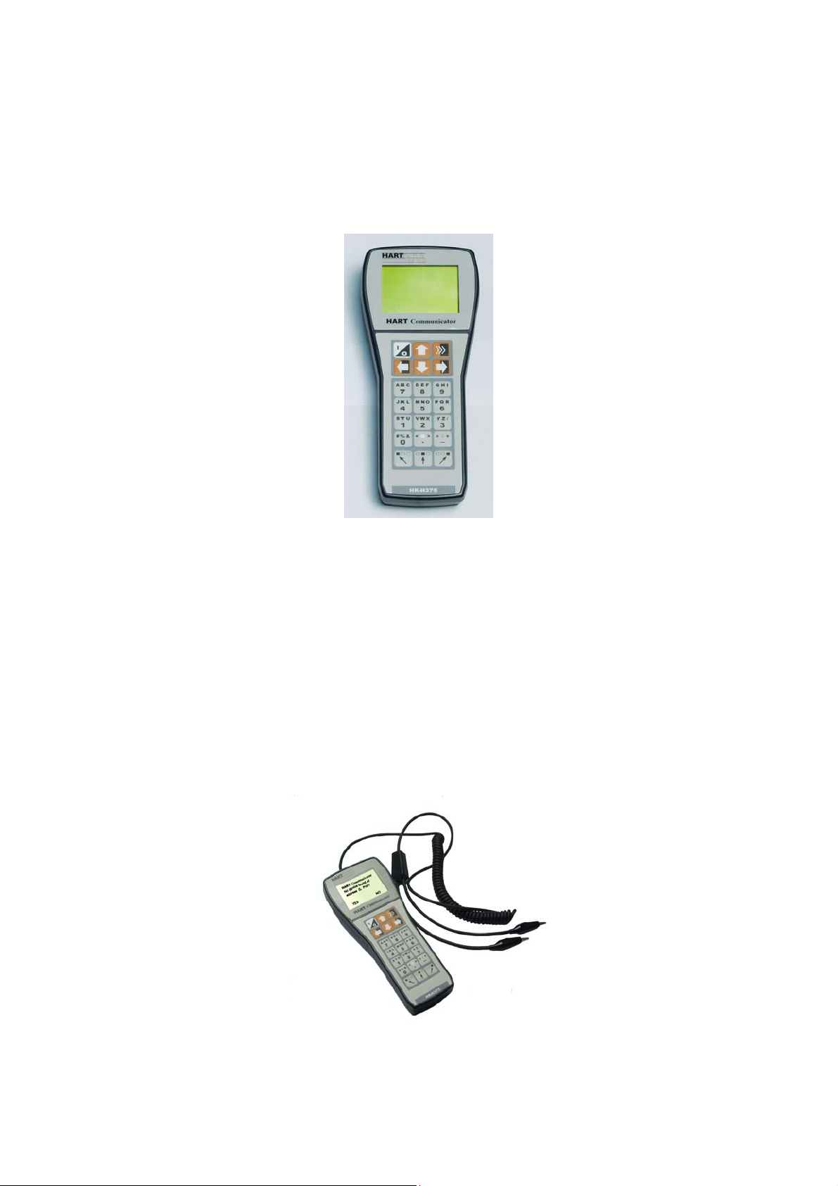
The HK-H375A HART Hand Held Communicator is a hand held interface based on HART
protocol, which can perform configuration, management, maintenance and adjustment to
all HARTcompatible instruments (Figure 1).
Figure 1 HK-H375A HART Hand Held Communicator
The HK-H375A HART Hand Held Communicator can be easily connected into 4~20mA
loop to achieve the configuration of instrument parameters (upper limit and lower limit etc.),
the reading of instrument variables, as well as the diagnosis and maintenance of the
instrument. This Communicator supports not only the HART main device (HART
multiplexer etc.), but also the peer-to-peer and multidrop HART communication modes.
1.2 Communicator Connections
This HART Communicator can interface with an instrument from the control room, the
instrument site, or any wiring termination point in the loop through the clips and cable
(which are the accessory of the communicator) (Figure 2).
Figure 2 Clips and Cable
6
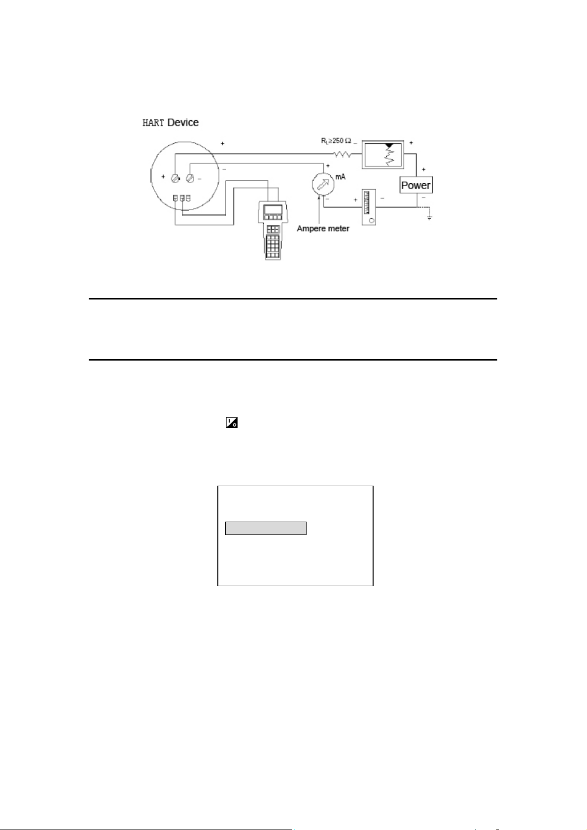
This HART Communicator could be connected in parallel with a HART instrument, or with
load resistor. All connections are non-polarized (Figure 3).
Figure 3 Communicator Connections
NOTE: For the HART Communicator to function properly, a minimum of 250 ohms
resistance must be present in the loop. The HART Communicator does not measure loop
current directly.
1.3 Power up
First make sure that batteries have been installed appropriately in the Communicator.
Then press the On/Off Key to power up the Communicator(once again for shut
down). Approximately for 5 seconds after the startup, the Communicator will automatically
poll the HART device (polling address 0) in the 4~20mA loop. If a device is not found, the
Communicator will display the message “No device found at address 0, Poll?” If a device
is found, the Communicator will display the Online Menu (Figure 4).
Figure 4 Online Menu
1.4 Quick Startup
1.4.1 Process Variables
When online, follow the menu operation sequence shown below to access Process
Variables:
Online Menu→1 Process Variables.
Online (********)
Device Setup
1 Process Variables
2 Diag/Service
3 Basic Setup
4 Detailed Setup

7
1.4.2 PV Unit
When online, follow the menu operation sequence shown below to access PV Unit:
Online Menu→4 Detailed Setup→2 Signal Condition→1 PV Unit.
1.4.3 Upper Range Value (URV)
When online, follow the menu operation sequence shown below to access Upper Range
Value:
Online Menu→4 Detailed Setup→2 Signal condition→2 PV URV.
1.4.4 Lower Range Value (LRV)
When online, follow the menu operation sequence shown below to access Lower Range
Value:
Online Menu→4 Detailed Setup→2 Signal condition→3 PV LRV.
1.4.5 PV Damping
When online, follow the menu operation sequence shown below to access PV Damping:
Online Menu→4 Detailed Setup→2 Signal condition→4 PV Damp.
1.4.6 D/A Trim
When online, follow the menu operation sequence shown below to access D/ATrim:
Online Menu→2 Diag/Service→3 Calibration→2 D/ATrim
NOTE: D/A Trim is usually done before the HART instruments leaves the factory or in the
periodic calibration of the instrument. Only qualified personnel should be perform this
operation, otherwise any inappropriate operation may increase the output error of the
HART instruments.
1.4.7 Zero Trim
When online, follow the menu operation sequence shown below to access Zero Trim:
Online Menu→2 Diag/Service→3 Calibration→3 Sensor Trim→1 Zero Trim
NOTE: Zero Trim can negate the zero error of the instrument caused by installation
method. Generally speaking, it is usually done at the first installation of the HART
instrument or during the scheduled calibration of the instrument. Only qualified personnel
should be designated to perform this operation, otherwise any inappropriate operation
may increase the output error of the HART instrument.

8
Section 2 Technical Specifications
2.1 Dimension
HK-H375A: 228mm x 98mm x 60mm
(Clips and cable not included)
2.2 HART®Connector
a) In conformity with HART Protocol (HCF);
b) Operating mode: intercommunication semiduplex 1200bit/s
c) Receivable voltage: ±40V
d) Leakage current less than 1uA at 20°C
e) Communication distance less than 1500m
f) Isolation mode: isolation between HART communication connector and power supply
g) Rating isolation voltage: 500Vrms
2.3 PC Connector
This connector is used for software update. Please contact Tel-Tru for information on
software updates.
2.4 Power Supply
Power Supply: 4.5V DC;
Power Consumption: 91.3mA (Typical value under working state)
1uA(Typical value under power-off state)
2.5 Battery
Power Supply: Three AA 1.5V alkaline batteries or rechargeable NiCad/NiMH batteries.
Battery Life: 100 hours (AAAlkaline Batteries)
80 hours (1000mA Rechargeable Batteries)
NOTE: The Communicator will shut down automatically if not used within 10 minutes.
2.6 Temperature Limit
Operating Temperature: 0°C ~+50°C
Storage Temperature: -20°C~+55°C
Note: The service lifetime of the LCD display will be shortened if the device is continuously
exposed to direct sunlight.
2.7 Liquid Crystal Display (LCD)
The LCD is an 8-line by 21 characters display that provides human-machine interface
(HMI). When the communicator is connected to a HART compatible device, the top line of
each Online Menu displays the model name and the tag of the device.
Typically, the performance of LCD displays will decrease if the ambient temperature is too

9
low. In order to meet your requirements for different ambient environments, a
temperature compensation circuit is embedded within the communicator, which enables
the LCD to display in good contrast and response time in colder environments.
Section 3 Keypad Instruction
3.1 On/Off Key
• Use this key to power up and power off the HART Communicator. Press this key for
at least 2 seconds.
3.2 Up Arrow Key
Use this key to move the cursor up through a menu or list of options.
3.3 Down Arrow Key
Use this key to move the cursor down through a menu or list of options.
3.4 Left Arrow/Previous Menu Key
Use this dual-function key to move the cursor to focus the left option or back to the
previous menu.
3.5 Right Arrow/Select Key
Use this dual-function to move the cursor to focus the right option or to select a menu
option.
3.6 Confirmation Key
Use this key to confirm the cursor-focused option.

10
Figure 5 Alphanumeric and Shift Keys
3.7 Alphanumeric & Shift Keys
Use Alphanumeric Keys to input data (Figure 5).
3.8 Using Shift Keys for Data Entry
Some menu requires data entry. Use the Up and Down Arrow Keys when available, or use
the Alphanumeric and Shift Keys to enter the alphanumeric information into the HART
Communicator.
If you press only the Alphanumeric Key with an edit menu, only the character in the center
of each key will be entered. These characters include digits from zero (0) to nine (9), the
decimal point (.), and the dash symbol (-). To enter the other characters on the keys, first
press and release the Shift Key corresponding to the position of the desired character on
the key and then press the Alphanumeric Key. Do not press the keys simultaneously. For
example, to enter the letter “R”, press the following key sequence:
Press the Shift Key again to deactivate the shift function.

11
Section 4 Common Tasks
If the Communicator is powered up when it is not connected to a device, the
Communicator will display the message “No device found at address 0, Poll?” Select “No”,
and then the Main Menu (Figure 6) appears.
If a device is found, the Communicator will skip the Main Menu, display the Online Menu
directly (Figure 7). You can access the Main Menu by pressing the previous menu key (left
key).
4.1 Main Menu
There are four functions in the Main Menu:
1.To access Online Menu;
2.To download software;
3.To read the battery capacity;
4.Polling.
You can access the Main Menu by pressing the previous menu key several times
whenever an instrument is connected.
Figure 6 Main Menu
4.2 Online Menu
If the Communicator is connected to a HART instrument, you can access the Online Menu
from the Main Menu.
Figure 7 Online Menu
4.3 Process Variables
When online, follow the menu operation sequence shown below to access Process
Variables:
Online Menu→1 Process Variables.
All process variables (PV, AO, PV%) are listed in the menu and updated at real time.
HART Communicator
1 Online
2 Download
3 Battery
4 Pollin
g
Online(*******)
Device setup
1 Process Variables
2 Diag/Service
3 Basic setup
4 Detail setup

12
Figure 8 Process Variables
4.4 Diag/Service
When online, follow the menu operation sequence shown below to access Process
Variables:
Online Menu→2 Diag/Service.
In Diag/Service Menu, there are three items: Test Device, Loop Test and Calibration.
Test Device can initiate a diagnostic routine on the device and report the result.
Loop Test can fix the transmitter output at a specified analogue value, in order to confirm
the integrity of the loop.
Calibration can perform sensor trim or analog output trim.
Figure 9 Diag/Service Menu
4.5 Basic Setup
When online, follow the menu operation sequence shown below to access Basic Setup:
Online Menu→3 Basic Setup.
This menu provides quick access to a number of configurable parameters. The
parameters available here are the most fundamental tasks that can be simply performed
with a given device. These tasks are a subset of the parameters available under the
Detailed Setup menu.
There are three types of menu item in this menu:
1. Submenu, access to the subordinate menu by pressing the Right Arrow Key
2. Variable display – note: some are read-only variables and some are writable
variables
3. Special functions, you can execute a series of operation here to achieve a
specific function, by just following the instructions on LCD.
Online(*******)
Process variables
1 PV ** KPA
2 AO ** mA
3 PV % ** %
Online(*******)
Diag/Service
1 Test Device
2 Loop test
3 Calibration

13
Figure 10 Basic Setup
4.6 Detailed Setup
When online, follow the menu operation sequence shown below to access Detailed Setup:
Online Menu→4 Detailed Setup.
This menu provides access to every editable device parameter and all device functions.
The Detailed Setup menu varies widely from one HART compatible device to another.
Figure 11 Detailed Setup
The Online Menu displays the name of the device on the top line of the LCD. You have
complete functionality for a specific device only when that device description (DD) is
preloaded in the HART Communicator.
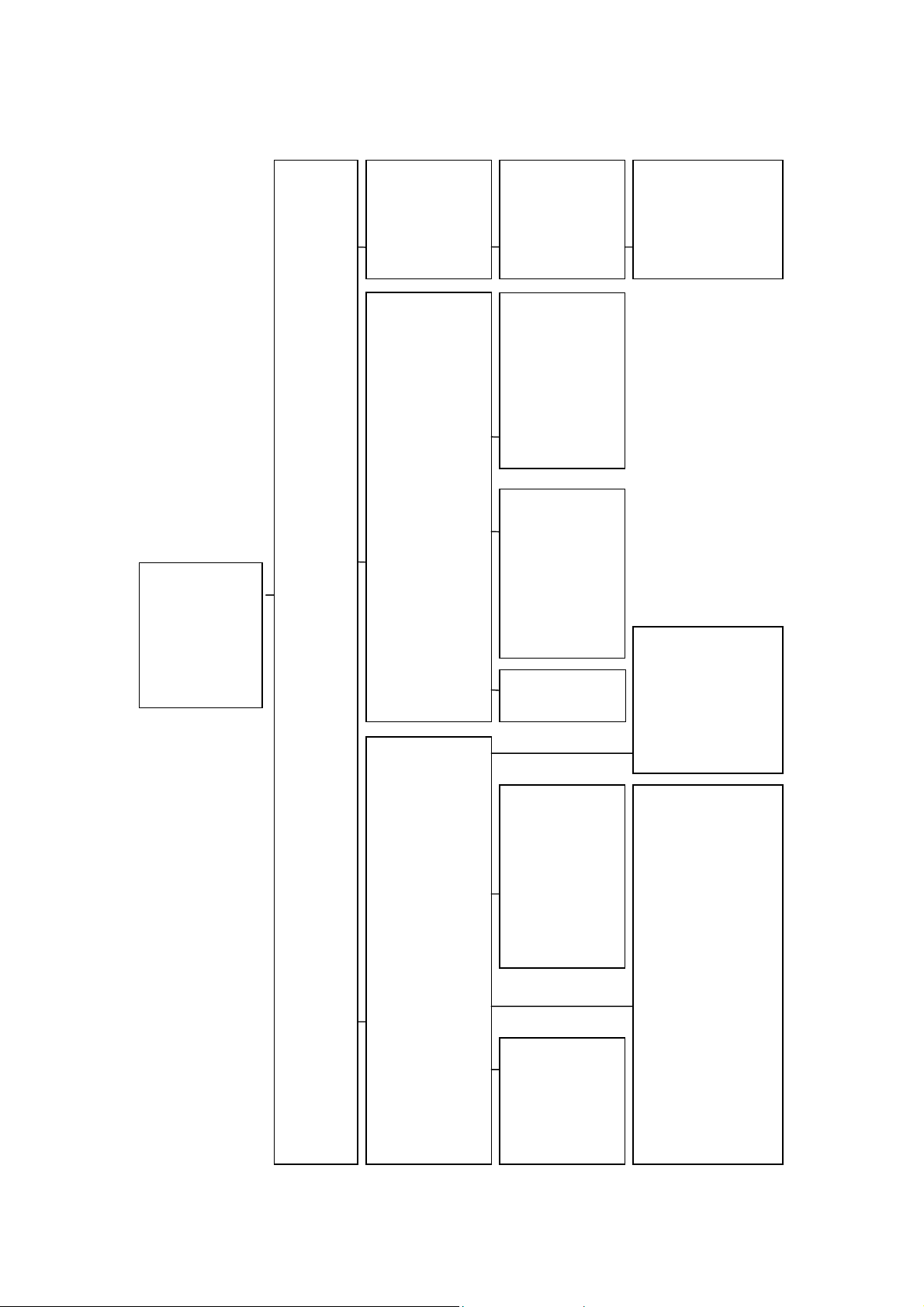
The Online Menu can be different depending on the connected device. Please refer to the
device-specific menu tree in the Appendix for the detailed information. When
communicating with a device without DD preloaded, the HART Communicator will display
a common menu tree(Figure 12). This menu tree could deal with all generic functions of
all HART compatible instruments.
Please refer to the device-specific menu tree in the Appendix for its special functions.
Online(*******)
Basic setup
1 Distributor
2 Model
3 Dev id
4 Tag
5 Device information
6 Revision
Online(*******)
Detailed setup
1 Sensor
2 Signal condition

14
Figure 12 Generic Online Menu Tree
1 Online
2 Download
3 Battery
4 Polling
1 Process
variables
2 Diag/
Service
3 Basic
setup
4 Detailed
setup
1 Test Device
2 Loop test
3 Calibration
1 Apply value
2 D/A trim
3 Sensor trim
1 Distributor
2 Model
3 Dev id
4 Tag
5 Device
information
6 Revision #’s
1 Date
2 Write Protect
3 Descriptor
4 Message
5 Final asmbly num
1 Sensor
2 Signal
condition
1 PV Snsr s/r
2 PV Snsr Unit
3 PV LSL
4 PV USL
5 PV Min span
1 PV Unit
2 PV URV
3 PV LRV
4 PV Damp
5 Xfer fnctn
6 AO Alrm type
1 Zero Trim
1 No req preams
2 Universal rev
3 Fld dev rev
4 Software rev
5 Hardware rev

15
4.7 Other Tasks
4.7.1 Automatic Polling
When online, the HK-H375A Hand Held Communicator will poll automatically the online
devices at address 0. If not connected to a device, the Communicator will display the
message “No device found at address 0, Poll?” Select “YES”, then the Communicator will
poll automatically all the devices connected from address1 to address 15.
When several devices are connected in the same loop, each device must be assigned a
unique address. If two devices share the same address, the communicator will not be able
to find the devices. At this point, the devices will need to be connected separately to
correct the polling address. HART Protocol defines the communication mode of
connecting several devices in the same loop as multidrop mode. Under multidrop mode,
the current in the loop will not be current signal of 4~20mA standard, but the sum of the
output current from all the devices.
4.7.2 Download
Follow the menu operation sequence shown below to access Download:
Main Menu→2 Download.
This function is designed for customers to easily update the DD in the HART
Communicator. We will update the DD periodically. Please do not hesitate to contact with
us for the relevant technical support.
This function is associated with the special PC software, downloading the target file into
the HART Communicator at the default baud rate 38400bit/s.
When the interface displays “Download target file”, select “OK”, then the download starts
and the Communicator will display “Please wait a moment...” When the download finished,
it will go back to the Main Menu.
Note: Please do not use this function without proper PC software and guidance from the
manufacture,
4.7.3 Battery
Follow the menu operation sequence shown below to access the Battery:
Main Menu→3 Battery.
This function will check the remaining battery capacity and display it in percent (%). When
the battery capacity is too low, please change the batteries at once to avoid influence on
the normal use of the Communicator.

16
4.7.4 Polling
Follow the menu operation sequence shown below to access Polling:
Main Menu→4 Polling.
When several devices are connected in the same loop (multidrop), you can achieve the
communication with the required device by polling (Figure 13).
Figure 13 Polling Menu
Item 1 is Single Polling, you can select any address between 0 and 15 to communicate;
Item 2, 3, and 4 is group polling; address 0~15 has been divided into three groups.
When a device is found by group polling, the Online Menu will display and communicate
with the lowest address found. To communicate with higher address devices, single
polling is necessary.
Polling
1 Single Polling
2 Polling Addr0-7
3 Polling Addr8-15
4 Polling Addr0-15

17
Section 5 Troubleshooting Communication Problems
5.1 No Communication With Field Device
① Check if the resistance in the loop is sufficient; loop resistance should be between 250
and 500 ohms.
② Check if the connection between the Communicator and the device is correct.
③ Check if the power supply of the device is correct.
④ Check if the device address is “0”; if not, select “YES” when it prompts “No device
found at address 0, Poll?” to poll all addresses and find online device.
5.2 Communicator Power up Failure
① Check if the Communicator has been installed with batteries.
② Check if the battery installation of the Communicator is correct.
③ Check if the battery capacity is sufficient.
5.3 Special Function Application Failure
You have complete functionality for a specific device only when that device description
(DD) is preloaded in the HART Communicator. If the DD is not preloaded in the HART
Communicator, please do not hesitate to contact us for the relevant technical support.
NOTE: This manual is subject to Copyright Laws
HART is registered trademark of HCF.

18
Appendix 1 Smart Products Menu Tree
1 Process
variables
2 Diag/
Service
3 Basic
setup
4 Detailed
setup
1 Test Device
2 Loop test
3 Calibration
1 Apply value
2 D/A trim
3 Sensor trim
1 Distributor
2 Model
3 Dev id
4 Tag
5 Device
information
6 Revision #’s
7 Meter options
1 Date
2 Write Protect
3 Descriptor
4 Message
5 Final asmbly
num
1 Sensor
2 Signal
condition
3 Field device info
4 Sensor
information
1 PV Snsr s/r
2 PV Snsr Unit
3 PV LSL
4 PV USL
5 PV Min span
1 PV Unit
2 PV URV
3 PV LRV
4 PV Damp
5 Xfer fnctn
6 AO Alrm type
1 Zero trim
2 Upper sensor trim
3 Lower sensor trim
4 Sensor trim points
1 Num req preams
2 Universal rev
3 Fld dev rev
4 Software rev
5 Hardware rev
1 Meter type
1 flange type
2 flange material
3 oring material
4 drain vent matl
5 remote seal type
6 seal fill fluid
7 rmt seal isol matl
8 num of rmt seals
9 module fill fluid
10 module isol matl
1 meas type
2 module range
3 characterize
1 Online
2 Battery
3 Polling

19
Appendix 2 Smart Products Shortcut Key
Function Shortcut Key
Upper sensor trim 2 , 3 , 3 , 2
Lower sensor trim 2 , 3 , 3 , 3
Meter type 3 , 7 , 1
Field device info 4 , 3
meas type 4 , 4 , 1
module range 4 , 4 , 2
characterize 4 , 4 , 3
20
Appendix 3 ROSEMOUNT 1151 Menu Tree
1 Process
variables
2 Diag
/Service
3 Basic
setup
4 Detailed
setup
1 Test Device
2 Loop test
3 Calibration
1 Apply value
2 D/A trim
3 sensor trim
1 Distributor
2 Model
3 Dev id
4 Tag
5 Device
information
6 Revision #’s
7 Meter options
1 Date
2 Write Protect
3 Descriptor
4 Message
5 Final asmbly
num
1 Sensor
2 Signal
condition
3 Field device
info
4 Sensor
infomation
1 PV Snsr s/r
2 PV Snsr Unit
3 PV LSL
4 PV USL
5 PV Min span
1 PV Unit
2 PV URV
3 PV LRV
4 PV Damp
5 Xfer fnctn
6 AO Alrm type
1 Zero trim
2 Upper sensor trim
3 Lower sensor trim
4 Sensor trim points
1 Num req preams
2 Universal rev
3 Fld dev rev
4 Software rev
5 Hardware rev
1 Meter type
1 flange type
2 flange material
3 oring material
4 drain vent matl
5 remote seal type
6 seal fill fluid
7 rmt seal isol matl
8 num of rmt seals
9 module fill fluid
10 module isol matl
1 meas type
2 module range
3 characterize
1 Online
2 Download
3 Battery
4 Polling
Table of contents


