Tela TGM133 User manual

TELA merilni sistemi
Scale Unit TGM133/134
Instruction Manual
ID 430 261 710 000, 4th Edition
TGM133/134 Instruction Manual May 2013 4th Edition 2/24
Safety Precautions
TELAms products are designed in full consideration of safety. However,
improper handling during operation or installation is dangerous and may
lead to fire, electric shock or other accidents, resulting in serious injury or
death. In addition, these actions may also worsen machine performance.
Therefore be sure to read this Manual before operating, installing,
maintaining, inspecting, repairing or otherwise working on this unit.
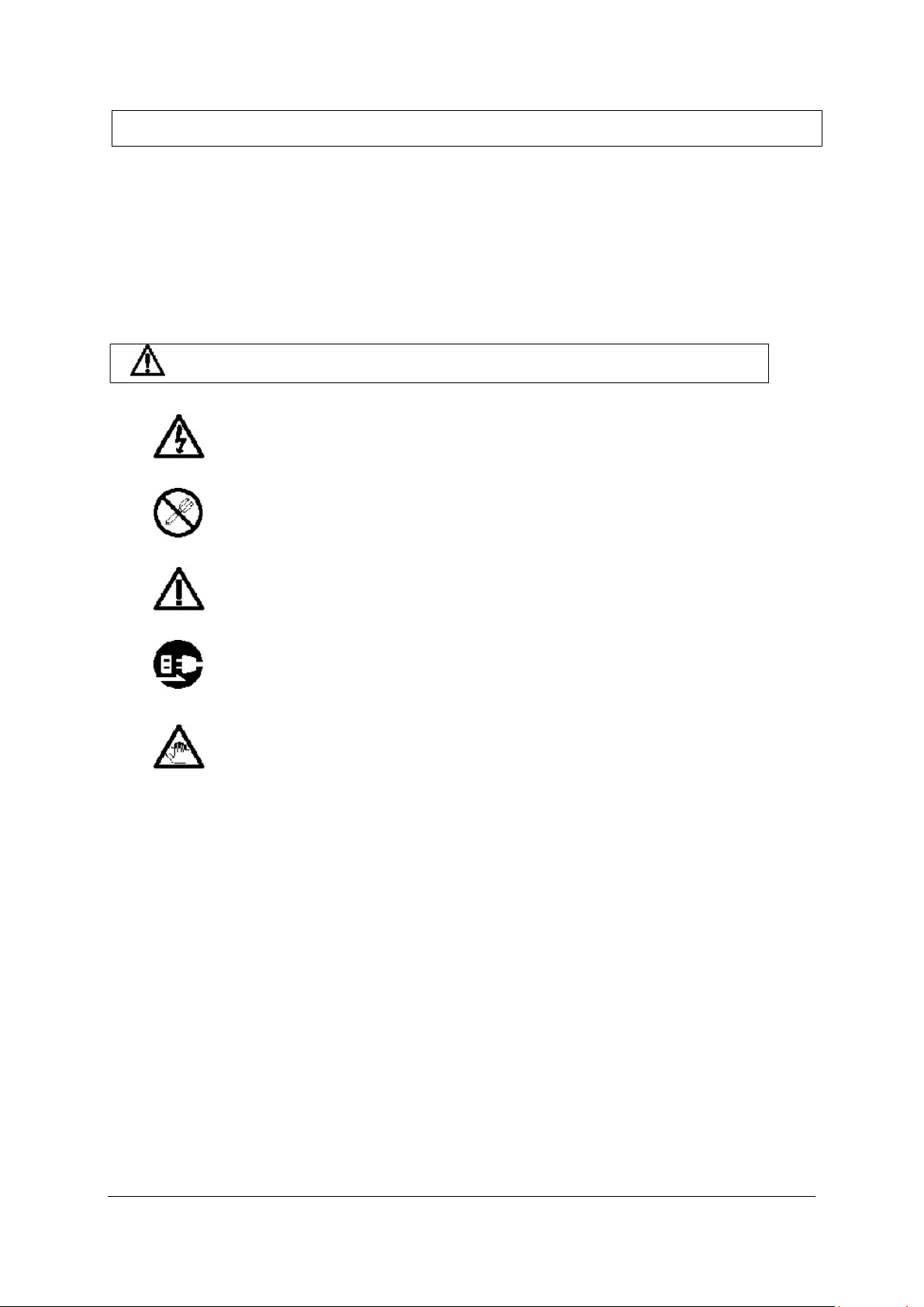
Warning, Caution
• Do not use this unit with voltages other than specified supply
voltage as this may result in fire or electric shock.
• Do not disassemble or modify the unit as this may result in injury or
damage the internal circuits.
• Be sure to check the machine and device conditions to ensure safety
work on a machine.
• Be sure to switch off the power supply, air and other sources of
drive power before working on the machine.
• When turning on a machine power supply, take care about moving
parts of a machine and corresponding devices.
General precautions
When using TELAms products, observe the following general precautions along
with those given specifically in this manual to ensure proper use of the products.
• Provide adequate safety measures to prevent damages in case the product
should develop malfunctions.
• Use outside indicated specifications or purposes and modification of our
products will void any warranty of functions and performances
• When using our products in combination with other equipment, the functions
and performances as noted in this manual may not be attained, depending on
operating and environmental conditions.

TGM133/134 Instruction Manual May 2013 4th Edition 3/24
Installation precautions
When installing this unit, care should be given to the following points to
prevent noise and electromagnetic wave interference from other equipment.
1. Do not pass lead and connection cables through the same ducts as
power lines.
2. Be sure to install the unit at least 0.5 m or more away from high voltage
or large current sources or high-power relays.
Installation place precautions
1. Mount the scale as closely as possible to the work-piece or to the object
being measured. Further the scale is mounted, greater is measuring error.
2. The scale unit should be used within an ambient temperature range of 0
to 50°C. Avoid locations where the scale is exposed to direct sunlight and
heat sources such as motors.
3. Do not place anything on the mounted scale, or step on it: excessive
force to the scale causes trouble.
Before installation
Do not disassemble parts other than scanning unit holder. All electrical
adjustments have also been completed before shipment. So do not tamper any
additional adjustment at time of its installation.
This scale unit consists of precision mechanism parts and electromagnetic
parts. Therefore, applying excessive pressure to the unit can seriously harm
the performance and service life of the scale. Be careful not to apply
excessive pressure to the scale unit when proceeding with the work.
When the unit is to be carried, support the scale unit and reading head
altogether. Do not hold the unit by the head cable, connectors, etc.
Ensure that the scale unit housing and reading head as well as the circuit
breaker for the supply power are properly grounded.
Standard procedure for EMC compliance.
When equipment such as controller does not function properly due to the effects
of large noise from power line please provide ground lines at one point
intensively. Power source which has a remote sensing function, must be used for
TGM133. Power unit without remote sensing unit may fail to prove optimum
functions. Please provide proper power source by referring to Section 5.

TGM133/134 Instruction Manual May 2013 4th Edition 4/24
Table of contest
1. Outline …………………………………………………….…...
5
1.1. Before Operation…………………………………………...…………………………….
5
1.2. List of Parts Supplied with the Scale Unit……………..……………………………
5
1.3. Model Configuration……………………………………….……………………………
6
2. Specifications………………………………………
…
…
…….
7
3. Name and Function of Part
s
……
…………………
……….
8
4. Mounting ………………………………………………
……….
9
4.1. Mounting Precautions……………………………………
…………………………….
9
4.1.1.
Checking the Mounting P
osture………………
……………………………………
9
4.1.2.
Setting the Operation R
ange…………………………
..
……
………………………
9
4.1.3.
Protection of the Head C
able…………………………..
……………………………
1
0
4.1.4.
Mounting the Protective C
over……………………...
...
……………………………
1
0
4.2.
Tools required for Scale I
nstallation……………………
……………………………
1
1
4.3
.
M
ount
ing procedure
…………………………………………
………………………
…
.
1
2
4.3
.1.
Mounting the Main U
nit
…………………………………
……………………………
1
2
4.3
.2. Mounting the Scanning Unit
………………………....
……………………………
1
3
4.3
.3. Removing the Scanning Unit Holder…………………
……………………………
1
4
4.3
.4. Checking the Operation Range
………………………
……………………………
1
5
4.3
.5. Attaching the Head Cable
…………………………….
……………………………
1
6
4.3
.6. Air Injection
……………………………………………….
…………………………
1
6
5. Connecting to
a
D
evice ……………………………
……….
1
8
5.1. Output Signal……………………………………………….
……………………………
1
8
5.2. Output connector
s
………………………………
…….
…
………
……………………
19
5.
3
. Alarm ( DS version optionally )………………………….
……………………………
2
1
6. Dimensions …………………………………………
…………
2
2
7. T
rouble prevention ………………………………….……….
24
TGM133/134 Instruction Manual May 2013 4th Edition 5/24
1. Outline
1-1. Before Operation
TGM133/134 series is small, light and high-accuracy optical feedback scale.
This series provides Line driver (A, A-, B, B-, RI, RI- digital output) or
Sinusoidal signals (1Vpp or 11µA output).
Output signals are adjusted before shipment, ex.-factory, each signal can be
readily used for connection to control device as it is.
1-2. List of standard parts supplied with scale unit
TGM133 Scale unit
Parts supplied with scale unit
HSB M8 x 20 2 (For mounting channel)
HSB M4 x 20 2 (For mounting scanning unit)
Cable clamp (small) 3 (For cable clamp)
+P M4 x 10 3 (For cable clamp)
Inspection certificate (Accuracy chart) 1
Instruction manual 1
Air injection valve 1
TGM133/134 Instruction Manual May 2013 4th Edition 6/24
1.3. Model configuration
TGM133-XX1-X2-XX3-X4-X5-XXXX6-XX7-X8-X9-X10
TGM134-XX1-X2-XX3-X4-X5-XXXX6-XX7-X8-X9-X10
Standard requirements
XX
1
Voltage supply
05 … 5V
X2 Resolution
0.1…0.1
m
0.5 … 0.5
m
1 … 1
m
XX
3
Output signals
DS
SI
SV
X4 Reference mark
0 … without
1 … in the middle
2 … on agreement
4 …
distance coded reference
X5 Accuracy
3 …
3
m
5 …
5
m
XXXX6
Measuring
length
Standard length [mm]
(see specifications on next page)
Special requirements:
XX
7
Cable length
3m : 03
Example: 1.5m : 1.5, 25m : 25
X
8
Connector
*
X9 Metal flexib
le
tube
0 … without
1 … with
X10 Mounting bar
0 … without
1…with: recommended for Lm
1240 mm,
required for Lm
1240mm
* Connector is defined with electrical versions SV, DS or SI:
1 … Amphenol 12 pin (DS)
4 … Conntact 12 pin connector (DS, SV)
5 … Conntact 9 pin connector (SI)
6 … Conntact 12 pin coupling (DS, SV)
7 … D-sub 9 pole (DS)
9 … other (specify)
0 … without connector
The difference between TGM133 and TGM134 see in section 6.

TGM133/134 Instruction Manual May 2013 4th Edition 7/24
2. Specifications
Items
Unit
TGM133
/134
Measuring length mm 70, 120, 170, 220, 270, 320, 370, 420, 470, 520, 570,
620, 670, 720, 770, 820, 920, 1020, 1140, 1240,
1340, 1440, 1540, 1640, 1740, 1840, 2040
Scale accuracy (at 20
C)
m
3,
5 (per meter)
Output Line driver: A, A-, B, B-, RI, RI-
Sinusoidal signal: 1Vp
p or 11
A
Reference point Distance Coded Reference (position is reproduced
by passing two adjacent reference marks that are
20 mm apart from each other.) (NOTE 1)
Resolution
m
0.1, 0.5, 1.0 (DS signals)
Signal period
m
20
Maximum response
speed m/min
20 (at 0.1 µm)
120 (SI, SV)
50 (at 0.5 µm)
60 (at 1.0 µm)
Scale temperature
expansion coefficient
K-1 (8.8 ± 1) X 10-6
Protection grade
Standard: IP53, with injecting air: IP64
Power supply +5 V 120mA max (DS)
+5 V 1
0
0mA max (SV, SI) (NOT
E 2)
Scanning unit sliding
resistance
N 3
Maximum capable cable
length
m Standard 3 (1, 5, 7, 10, 15, 20, 25, 30, 50, 100, 150
possible) (NOTE 3)
Operating temperature
°C
0 to +50
Storage temperature
°C
-
30 to +70
Operating humidity
%RH
30 to 90 (No
condensation)
Vibration resistance
m/s
2
70
Shock resistance
m/s
2
300
(NOTE 1) Any one location can be designated as the reference point, and
multiple reference points (at a pitch of 20 mm) can also be supported.
(NOTE 2) When load resistance of A/B/RI/ALM is 120, refer to section 5-3
for details of power voltage.
(NOTE 3) SV can perform output range of 0.6 V to 1.2 V as A/B phase output
with 150 m cable made by TELAms.
TGM133/134 Instruction Manual May 2013 4th Edition 8/24
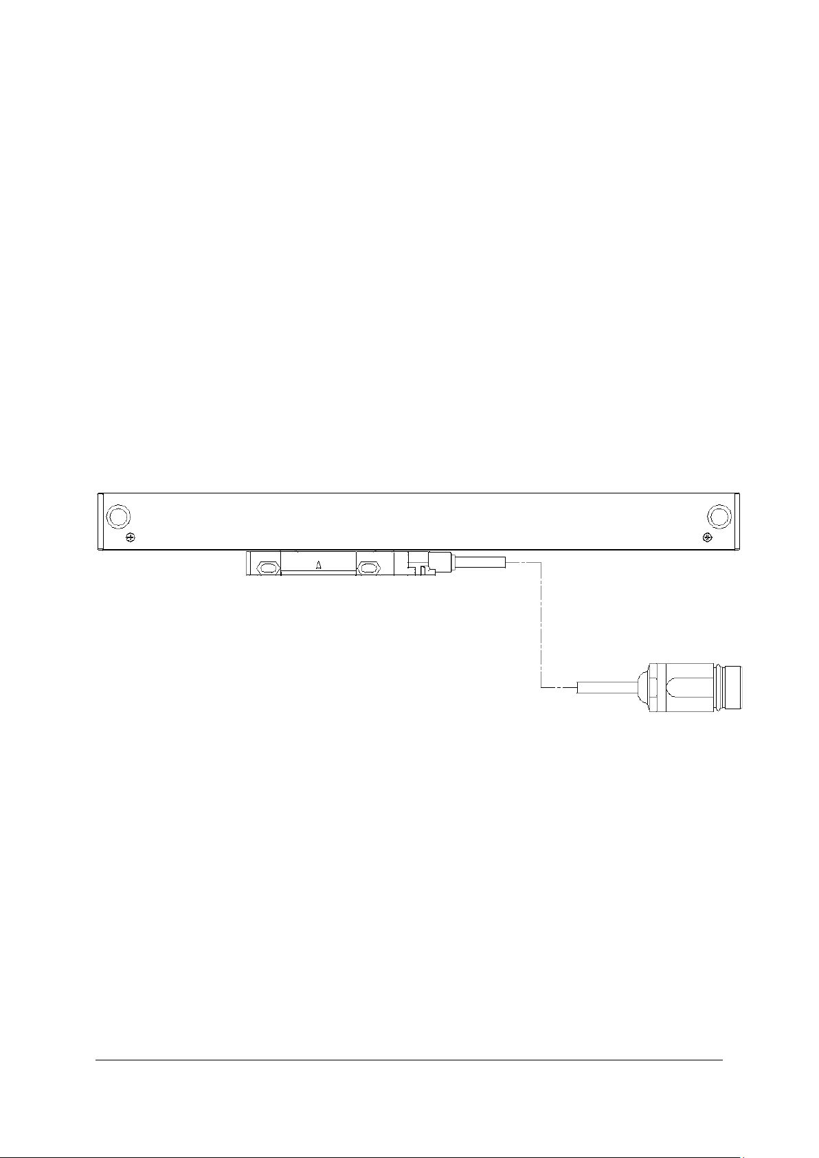
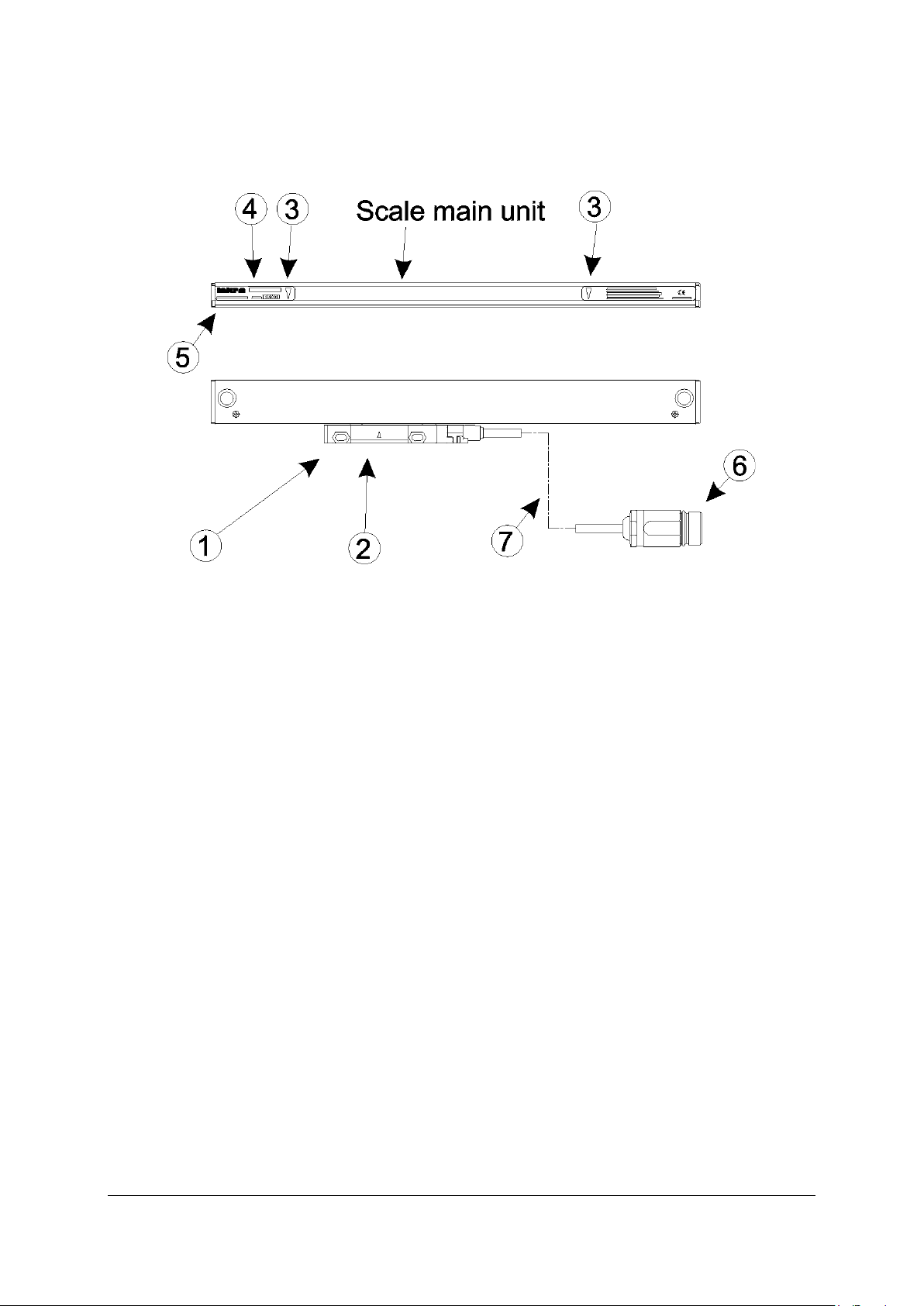
3. Name and Function of Parts
Reading head
This holds the scanning unit. When shipped, it is secured with a scanning unit
holder.
Centre of scanning unit
This indicates the mechanical centre of the scanning unit. It serves as a
reference when viewing the relative position to the measuring length marks.
Measuring length marks
These indicate the effective movement range over which accuracy is assured
with respect to the centre of scanning unit. The measuring length represents
the length of the effective movement range.
Note
When mounting and using the scale unit, be sure to operate the unit within
this range. Using the scale unit in excess of the effective movement range
may damage the unit.
Model name
This indicates the scale unit model name.
Serial No.
This indicates the scale unit serial No.
Connector.
Head cable.
TGM133/134 Instruction Manual May 2013 4th Edition 9/24
4. Mounting
4-1. Mounting precautions
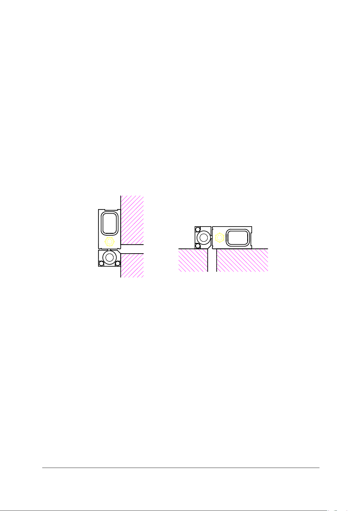
4-1-1. Checking the mounting posture
Check that the scale unit can be mounted in the relative positions shown in the
Fig. 4-1.
Do not mount the scale in any other posture otherwise difficulties in servicing
and maintenance may arise.
The mounting position A in particular is recommended: cutting oil and chips
may be effectively kept out.
Do not install at Position B, in case cutting oils or coolant may fall on the scale.
A B
Fig. 4-1
When a scale is installed on a vertical axis it should be mounted in such a
manner that its scanning unit will face opposite to a work piece (cutting tool).
4-1-2. Setting the operation range
• The measuring length of scale is the distance between the measuring length
marks at the both ends of the scale.
• Mount the scale in such a position that the slider center moves within these
measuring length marks.
• Take special care not to move the scanning unit beyond the range between
measurement length marks otherwise the scale may be damaged.
Mechanical limit mechanism (stoppers, etc.) is required if scanning unit needs
to move for its full stroke in measurement length near to measurement length
marks.

TGM133/134 Instruction Manual May 2013 4th Edition 10/24
Measuring length mark
Be sure to install the scale that the center of scanning unit is held in this area.
Fig. 4-2
4-1-3. Protection of the head cable
The head cable is secured on a slider with screw.
Take care not to pull the cable forcefully or bend it repeatedly otherwise the
cable may be broken or a connector may be damaged.
4-1-4. Mounting a protective cover
If chips or coolant will be splattered directly onto the scale during operation, it is
recommended that a cover which will hide it as much from outside view as
possible be mounted in order to maintain the scale’s performance. Such a cover
is shown in Fig. 4-3.
Fig. 4-3

TGM133/134 Instruction Manual May 2013 4th Edition 11/24
4-2. Tools required for scale installation
In addition to accessories, prepare following tools.
• Bracket for mounting scale (Refer to Fig. 3-4) 1 or 2
• Bracket for mounting scanning unit (Refer to Fig. 3-4)
• 0.01mm pick tester (or Dial gauge) 1 or 2
• Hexagon wrench for M4 (3mm) 1
• Hexagon wrench for M8 (6mm) 1
• Driver No.2 (+) 1
• Tap M4 1
• Tap M8 1
• Drill 3.2 1
• Drill 6.8 1
• Thickness gage = 0,7 mm 1
• Thickness gage = 1,0 mm 1
• Thickness gage = 1,4 mm 1
Accessories
HSB M8 x 20 2 (For mounting channel)
HSB M4 x 20 2 (For mounting scanning unit)
Cable clamp (small) 4
+P M4 x 10 4 (For cable clamp)

TGM133/134 Instruction Manual May 2013 4th Edition 12/24
4-3. Mounting procedure
4-3-1. Mounting scale main unit
1. Machine the mounting surface of the scale main unit to a flatness of 0.1
mm/M (where “M” is the machine guide) over the entire length of the
mounting area.
Fig. 4-4
Although Fig. 3-4 shows that brackets are being used, they are not needed if
the mounting surface of the machine main unit has already been machined to
the designated flatness before the scale is mounted.
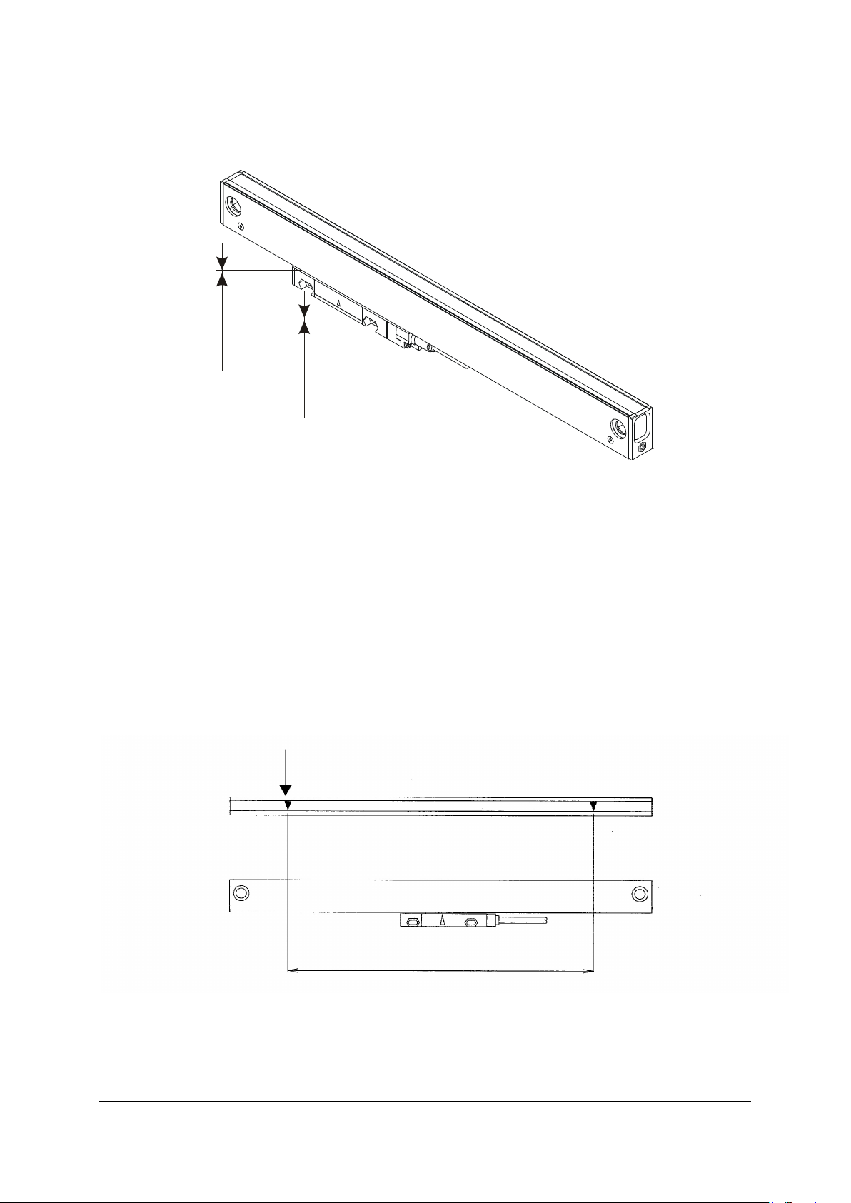
2. Check the flatness of the mounting surface, and then attach the scale main
unit to this surface by tightening up the M8 x 20 screws.
Check the parallelism of the top surface of the scale unit at both ends across
a range of 40 mm at each end as shown in Fig. 3-5. The allowable
parallelism value is 0.1 mm.
Fig. 4-5
After adjusting the parallelism to 0.1 mm, attach the M8 screws using a
tightening torque of 22 Nm (220 kgf.cm).
TGM133/134 Instruction Manual May 2013 4th Edition 13/24
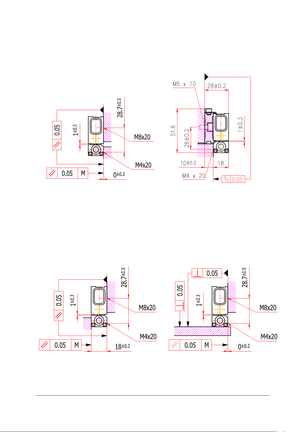
4-3-2. Mounting scanning unit
Setting mounting surface of scanning unit and mounting tolerances (“M” is
the machine guide)
without mounting bar with mounting bar
Fig. 4-6
• The mounting surface must be clean
- free of paint
- dry and without chips
It is also possible to mount in the following condition.
Fig. 4-7

TGM133/134 Instruction Manual May 2013 4th Edition 14/24
Mounting scanning unit
Mount screws with scanning unit holder fixed in order to change
dimensions.
Use screws of two HSB M4 x 20 at screw torque 2.5 Nm (25 kgf.cm).
M4x20
M4x20
Fig. 4-8
4-3-3. Removing scanning unit holder
The scanning unit holder can be removed in a single-action operation. When, as
shown in Fig. 4-9A, area is pressed, the tab attached to the scanning unit is
disengaged so that the scanning unit can then be moved in the lengthwise
direction of the scale unit and completely separated from the scale unit. The
scanning unit holder can now be removed by lifting it free from the scale unit.
1
2
3
Fig. 4-9 A
TGM133/134 Instruction Manual May 2013 4th Edition 15/24
Make sure to install the edge of scanning unit within
1 ± 0.3 mm range.
1
±
0
.
3
1±0.3
Fig. 4-9 B
4.3.4. Checking the operation range
After mounting the scale and scanning unit, be sure to always move the machine
over its entire length to check that the machine movement range is within the
scale measuring length.
Be careful that the scale movement range does not exceed the scale measuring
length + range of movement. If it does, the scale can be damaged.
Fig. 4-10

TGM133/134 Instruction Manual May 2013 4th Edition 16/24
4-3-5. Attaching the head cable
Secure the head cable with a cable clamp so that it does not get entangled.
Note
Note that the wiring should be made to allow enough room for machine
movement during operation.
Fig. 4-11
4.3.6. Air injection
Air can be injected from both sides of the scale side cover (or, optionally, from
the slider).
In the case of using scale unit under circumstances as follows, clean air injection
will minimize their influence.
Dusty
High humidity
Probable condensation inside scale by temperature and humidity change
Actual effects are different depending on working condition. Adopt after
verifying effects enough.
B: Optionally provided
Fig. 4-12
A B
C

TGM133/134 Instruction Manual May 2013 4th Edition 17/24
Air injection to upper scale unit (A) and air injection to slider connector (C) on
Fig. 4-12, is possible with nipple in accessory. But air injection to slider (B) is
optional, so separate order for it required.
An example of air pipe route and device configuration is shown as follows.
Fig. 4-13
The air supply unit and equipment are provided by the customer.
Specifications of standard device are shown for your reference.
Item
Specifications
Guaranteed maximum pressure
1.5 MPa
Max. working pressure
1020 kPa
Adjustable pressure range
20 to 200 kPa
Working fluid
Air
Ambient temperature and working fluid
temperature
-5 to 30°C
(No condensation)
Filtration grade
Air filter: 5 µm
Mist separator: 0.3 µm
Pressure gauge tester connecting bore
2
-
RC (PT) 1/8
Pipe connecting bore IN side: Tube shape
8
OUT side: Tube shape
6
Automatic drain working pressure
150 to 1020 kPa
Table 4-1
Connect to scale
Tube bend radius R15 mm or more
Outside diameter
6, Inside
diameter 4 polyurethane tube
Outside diameter
8 Nylon tube
Distribution parts
Pressure reducer
Filter 5
m Mist separator (0.3
m)
TGM133/134 Instruction Manual May 2013 4th Edition 18/24
5. Connecting to device
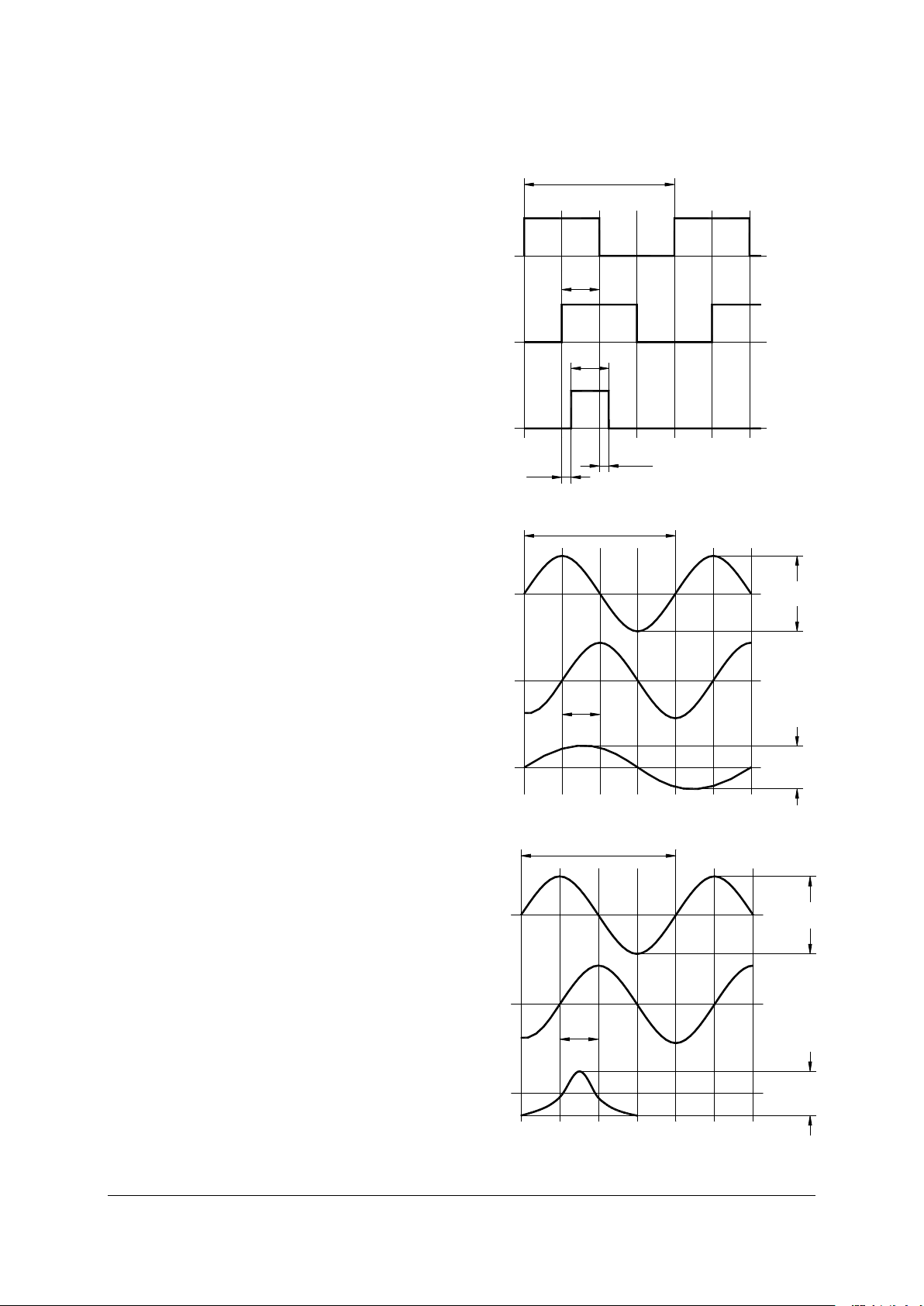
5.1. Output signals
Digital output – DS (TTL):
supply 5V (150mA max.)
t 0.1 s
Sinusoidal output – SV (1Vpp) :
supply 5V (100mA max.)
U0 = 2.5V (Ud/2)
= 20 m
Sinusoidal output – SI (11µA) :
supply 5V (100mA)
Fig. 5-1
Fig. 5-2
RI
B
A
360°
90°
90°
tt
90°
0.5Vp-p
U0RI
360°
U0
U0
B
A
1Vp-p
7-16Ap-p
2-8Ap-p
IRIo
Ibo
90°
360°
Iao
Fig. 5-3
TGM133/134 Instruction Manual May 2013 4th Edition 19/24
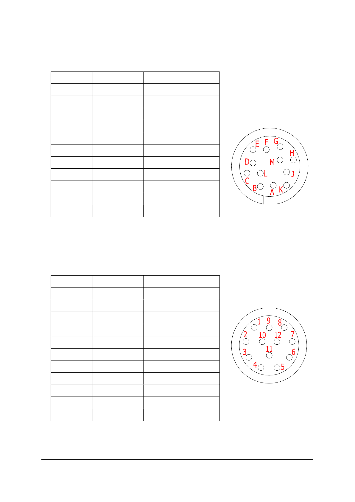
5.2. Output connectors
Digital output - DS, 12 pin Amphenol connector:
L B BLACK
D A BROWN
H RI GREY
E BLUE (isolate)
B 0V GREEN/WHITE
0V (sens) VIOLET
E B RED
C A GREEN
G RI PINK
K +5V GREEN/YELLOW
+5V (sens) WHITE
Housing shield SHIELD
Connect shield to connector housing
Digital output - DS, 12 pin Contact connector or coupling:
1 B BLACK
6 A BROWN
4 RI GREY
7 E BLUE
10 0V GREEN/WHITE
11 0V (sens) VIOLET
8 B RED
5 A GREEN
3 RI PINK
12 +5V GREEN/YELLOW
2 +5V (sens) WHITE
Housing shield SHIELD
Connect shield to connector housing
Fig. 5-5
Fig. 5-4
TGM133/134 Instruction Manual May 2013 4th Edition 20/24
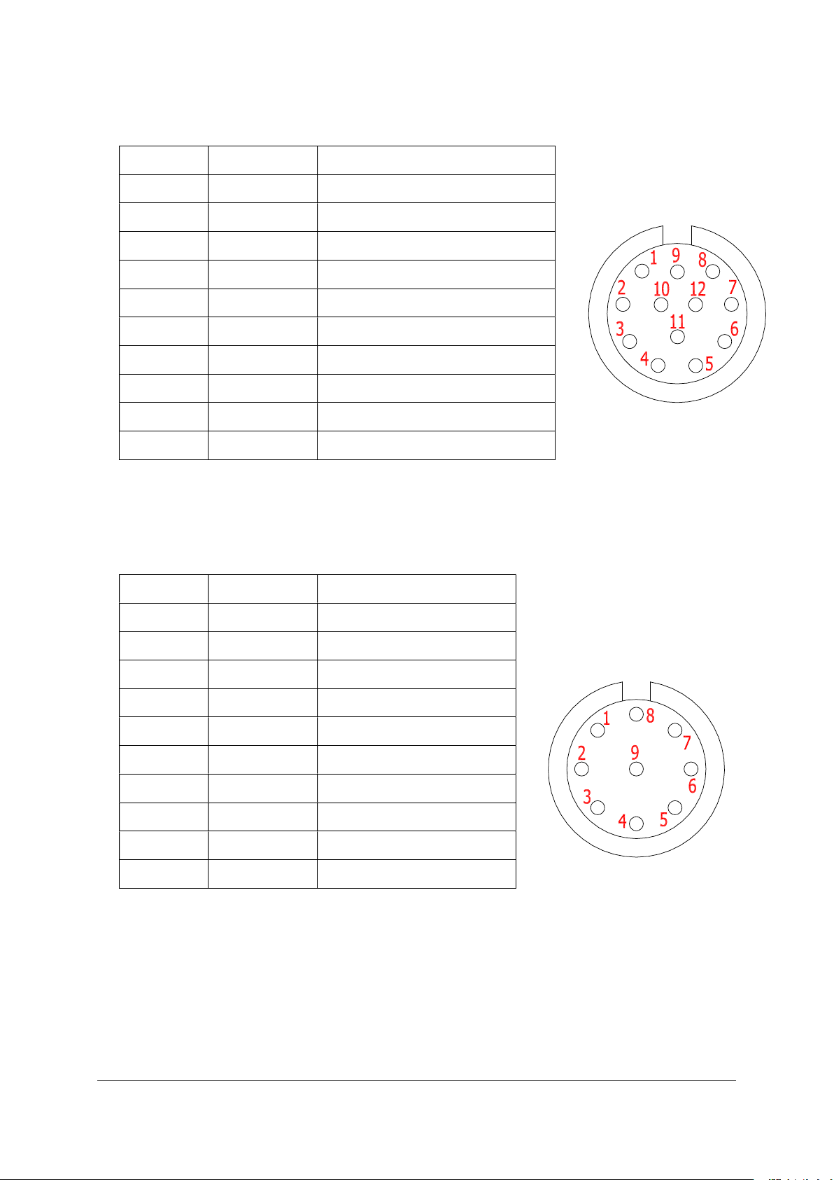
Sinusoidal output – SV (1Vpp), 12 pin Contact connector or coupling:
1 UB RED
6 UA BROWN
4 URI PINK
10 0V GREEN/WHITE + VIOLET
11 0V (sens) BLUE
8 U B BLACK
5 U A GREEN
3 U RI GREY
12 +5V GREEN/YELLOW
2 +5V (sens) WHITE
Housing shield SHIELD
Connect shield to connector housing
Sinusoidal output – SI (11App), 9 pin Contact connector:
6 Ib- RED
2 Ia- BROWN
8 Iri- PINK
4 0V GREEN/WHITE
4 0V VIOLET, BLUE
5 Ib+ BLACK
1 Ia+ GREEN
7 Iri+ GREY
3 +5V GREEN/YELLOW
3 +5V WHITE
Housing (Shield) SHIELD
Connect shield to connector housing
Wires for signals must be twisted pairs, cross section 0.14 mm2 (AWG26)
and voltage supply wires 0,25 mm2 (AWG22), Calculated
Structure: Twisted wire, Electrical resistance: 141 /km or less
Shielding structure: all wires must be covered with braided shield
Fig. 5-6
Fig. 5-7
This manual suits for next models
1
Table of contents


