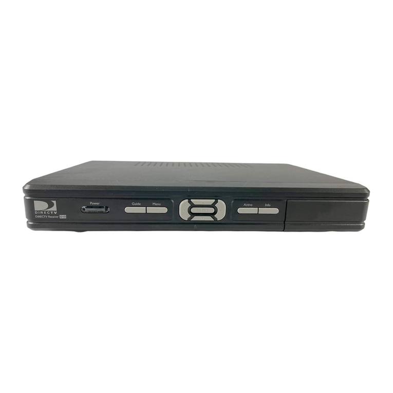
Tele King 410 User manual

PHOTO
FACT*
Fold
er
TELE
KING
MODELS
41O,
512,
612,
71O
VOLUME
CONTROL
ON-OFF
SWITCH
HORIZ
VERT.
HOLD
CONTRAST
BRIGHTNESS
CHANNEL
SELECTOR
FINE
TUNING
TELE
KING
MODEL
410
TRADE
NAME
Tele
King
Models410,512,612,
710
MANUFACTURER
Tele
King
Corp.
,
601
W.
26th
St.,
New
York
1,New
York
TYPE
SET
TelevisionReceiver
TUBES
Twenty
POWER
SUPPLY
110-120
Volts
AC-60
Cycle
TUNING
RANGE-Channels
2
thru
13
RATING
1.62
Amp.
at117
Volts
AC
Alignment
Instructions
6
Block
Diagram
13
Horiz.
Osc.
Adjustment
6
Parts
List
and
Description
14,15,16
Photographs
Cabinet-Rear
View
7
CapacitorIdentification
11,18
Chassis-Top
View
3,7
INDEX
Photographs
(continued)
RF
Tuner
10
Resistor
Identification
12,17
Trans.,
Inductor
and
Alignment
Identification..
. 4,9
S
chematic
2
Tube
PlacementChart
5
Voltage
and
Resistance
Measurements
8
o
o
m
Om
>
in
2
3
Z
to
N
^
O
HOWARD
W.
SAMS
&
CO.,INC.
•
Indianapolis
1,
Indiana
"Thelisting
ofany
available
replacement
part
hereindoes
not
constitute
inany
case
a
recommendation,warranty
or
guaranty
by
Howard
W.
Sams
&
Co.,Inc.,
as
tothe
quality
and
suitability
of
such
replacement
part.
The
numbers
of
these
parts
have
been
compiled
frominformationfurnished
to
Howard
W.
Sams
&
Co.,
Inc.,
by the
manufacturers
of the
particulartype
of
replacement
part
listed."
"Reproduction
or
use,without
express
permission,
of
editorial
or
pictorial
con-
tent,
inany
manner,
is
prohibited.
No
patent
liability
is
assumedwithrespect
to
the
useofthe
informationcontainedherein.Copyright
1950
by
Howard
W.
Sams
&
Co.,Inc.,Indianapolis
1,
Indiana,
U.S.of
America.Copyrightunder
In-
ternational
CopyrightUnion.
All
rights
reserved
under
Inter-American
Copyright
Union
(1
91
0)
by
Howard
W.
Sams
&
Co.,
Inc."Printed
in
U.S.of
America
DATE
3-50
SET
88
FOLDER
12

THE
COOPERATION
OFTHE
MANUFACTURER
OF
THIS
RECEIVER
MAKES
IT
POSSIBLE
TO
BRING
YOU
THIS
SERVICE
A
PHOTOFACTSTANDARD
NOTATION
SCHEMATIC
©Howard
W.
Sams
&
Co.,Inc.1950
PAGE
2

AUDIO
OUTPUT
jz)
6AQ5
si

88-12

TELE
KING
MODELS
410,
512,612,
712
M3IA
dOl
SISSVhD

(m)

EfiS?*
.
V^Vu"
CHASSIS
BOTTOM
VIEW-TRANS.JNDUCTOR
AND
ALIGNMENT
IDENTIFICATION
LIZ.
'£L9
'tiS
'OLfr
S13QOW
9NIX
3131

VIDEO
DET.-AGC
3HD.VIDEOIF
2.NDVIDEOIF
HOR.
OUT
F>UT
H
ORZ.MULT.
AUDIO
OUTPLTT
/V\
RFAMP
(V4
\T
VIDEOIF
2ND
VIDEOIF
3RDVIDEO1F
VIDEO
DET
A7io\
SOUND
IF
/V9\
BOTTOM
VIEW
AUDIO
OUTPUT
VIS
\ VI6
\
V!7
V
6SN7GTJ
\6
j
I
6W4G6y
|HORIZ.MULT
V.
^
DAMPER
,
HORIZ.
OUTPUT
I
I
VIS
IB3GT
,
TUBE
PLACEMENT
CHART
siaaow
9NIX
3131

ALIGNMENT
INSTRUCTIONS
To
eliminate
the
high
voltage
shock
hazard
remove
the
horizontal
oscillator
tube(V15) from
its
socket.
VIDEO
IF
ALIGNMENT
The
useofa
VTVM
with
anAC
scale
is
necessary
to
align
the
video
IF
stages,
donot
attempt
to
connect
the
VTVM
across
the
diode
load
resistor.
Remove
the
local
oscillator
tube
(V3)from
its
socket
to
prevent
erroneous
indications.
Set
the
contrast
control
to
slightly
less
thanmaximumclockwise.
DUMMY
ANTENNA
Direct
Direct
SIGNAL
GENERATOR
COUPLING
High
side
to
ungrounded
tubeshieldfloating
over
mixer
tube
(V2).
Low
side
to
chassis.
SIGNAL
GENERATOR
FREQUENCY
25.6MC
(400
-
AM
modulated)
23.4MC
(400
-
AM
modulated)
CHANNEL
Any
CONNECT
VTVM
AC
Probe
to
Point<£>
Common
to
chassis,
(see
instructions
above)
"
ADJUST
A1.A2
A3.A4
REMARKS
Adjust
for
maximumdeflection.
OVERAttVIDEO
IF
RESPONSE
CHECK
Connect
the
synchronized
sweepvoltage
from
the
signal
generator
tothe
horizontal
input
ofthe
oscilloscope
for
horizontal
deflection.
DUMMY
ANTENNA
Direct
SWEEP
GENERATOR
COUPLING
High
side
to
ungrounded
tube
shieldfloating
over
mixertube
(V2).
Low
side
to
chassis.
SWEEP
GENERATOR
FREQUENCY
25MC
(10MC
SWP)
MARKER
GENERATOR
FREQUENCY
26.
IMC
25.6MC
22.6MC
21.6MC
CHANNEL
Any
CONNECT
SCOPE
Vert.
Amp.
to
Point
<Q>
Low
side
to
chas-
sis.
ADJUST
REMARKS
Check
for
response
curve
similar
toFig1
with
markers
as
shown.
If
necessary
retouch
Al
thru
A4for
proper
response.
SOUND
IF
ALIGNMENTUSING
AM
SIGNALGENERATOR
AND
VTVM
Connect
a
matchedpair
of
100KJ2
resistors
betweenpoints
B,andC.The
junction
of
these
resistors
is
alignmentpoint
E.
DUMMY
ANTENNA
.
01MFD
.
01MFD
SIGNAL
GENERATOR
COUPLING
High
side
topin4
(Grid)
of
6AC7
(V8)
.
Low
side
to
chassis.
SIGNAL
GENERATOR
FREQUENCY
4.
SMC
(Unmod.)
CHANNEL
Any
chan-
nelnot
used
local-
ly
"
CONNECT
VTVM
DC
Probe
to
PoinKrp
Common
to
Point<C>
DC
Probe
to
Point<^>
Common
to
Point<jS
ADJUST
AS,
A6,
A7
A8
REMARKS
Adjust
for
maximumdeflection.
Adjust
for
zero
reading.
A
positive
and
negative
readingwill
be
obtained
on
either
side
of
the
correct
setting.
SOUND
IF
ALIGNMENTUSING
FM
SIGNALGENERATOR
AND
OSCILLOSCOPE
Use
frequencymodulated
signal
with
60
~
modulation
and
450KC
sweep.
Use120
~
sawtooth
voltage
in
scope
for
horizontaldeflection.
DUMMY
ANTENNA
.
01MFD
.
01MFD
SWEEP
GENERATOR
COUPLING
High
side
topin4
(Grid)
of
6AC7
(V8).
Low
side
to
chassis.
SWEEP
GENERATOR
FREQUENCY
4.
SMC
(450KC
SWP)
MARKER
GENERATOR
FREQUENCY
4.
SMC
CHANNEL
Any
channel
not
used
locally.
CONNECT
SCOPE
Yert.
Amp.
to
Point
<^>
Low
side
to
chas-
sis.
Vert.
Amp.
to
Point
<£>
Low
side
to
chas-
sis.
ADJUST
A5.A6,
A7
A8
REMARKS
Disconnect
stabilizer
capacitor
C6.
Adjust
for
maximumamplitude
and
symmetry
as
perFig2.
Reconnect
capacitor
C6.
Adjust
A8so
4.
SMC
occurs
at
center
of
crossover
lines
asperFig
3
.
SLIGHTLYretouch
A7for
maximum
amplitude
and
straightness
of
crossover
lines.
TINER
ALIGNMENT
The
circuits
in
the
tunerhavebeen
pre-set
atthe
factory
andare
sufficiently
broad
and
should
not
require
adjustment
inthe
field.
FIG.
I
FIG.
2
F,G
3
HORIZONTALOSCILLATOR
ADJUSTMENTS
Turn
thesetonand
tune
ina TV
station,preferably
a
test
pattern.
Set
the
horizontalholdcontrol
tothemid
position
ofits
range.
Adjust
the
horizontalfrequencyslug
(BI)
until
the
picture
synchronizes
horizontally.
Turn
the
horizontal
drivetrimmer(B2)clockwise
asfaras
possible
withoutcrowding
the
right
side
ofthe
picture.
Adjust
the
width
slug
(B3)until
the
picture
fills
the
maskhorizontally.
Adjust
the
horizontallinearity
slug
until
the
picture
is
symmetrical
from
left
to
right,readjustment
ofB2maybe
required
to
obtain
optimum
results.
PAGE
6

CHASSIS-TOP
VIEW
VER"
LIN
VERT
SOUND
HORlZ,
HORIZ
SIZEDISC.
FREQ.
DRIVE
i
WIDTH
CABINET-REAR
VIEW
PAGE
7

VOLTAGE
AND
RESISTANCE
MEASUREMENTS
VOLTAGE
READINGS
RESISTANCE
READINGS
Item
V
1
V
2
V
3
V
4
V
5
V
6
V
7
V
8
V9
V
10
V1 1
V
12
V
13
V14
V
15
V
16
V
17
vie
V
19
V20
Tube
6BH6
6AG5
6J6
6AU6
6AU6
6AU6
6AL5
6AC7
12AU7
6AU6
6T8
6AQ5
6SN7GT
6AL5
6SN7GT
6BG6G
6W4GT
1B3GT
5U4G
12LP4
Pin
1
-
.
4VDC
-1VDC
95VDC
-1.9VDC
-.1VDC
0V.
0V.
0V.
2.SVDC
tl.lVDC
t-.4VDC
t-.6VDC
-20VDC
0V.
.1VDC
0V.
0V.
Pin
2
.1VDC
0V.
95VDC
0V.
0V.
0V.
-3VDC
6.
3
VAC
0V.
f7.2VDC
t-.8VDC
tov.
75VDC
185VDC
0V.
250TOC
6.
3
VAC
0V.
Pin
3
0V.
6
.
3V
AC
6.
3
VAC
6.
3
VAC
6.
3
VAC
6.
3
VAC
6.
3
VAC
2.8VDC
.7VDC
tov.
t-.4VDC
tov.
0V.
0V.
10VDC
7VDC
430VDC
Pin
4
6.
3
VAC
0V.
0V.
0V.
0V.
0V.
0V.
-2.5VDC
0V.
te.svAc
te
.
SVAC
te.svAc
ov.
6.
3
VAC
ov.
ov.
ov.
Pin
5
55VDC
55VDC
§-2.2VDC
55VDC
55VDC
55VDC
-1.6VDC
2.8VDC
OV.
tSSOVDC
tov.
t!45VDC
290VDC
1.8VDC
105VDC
-4VDC
360VDC
Pin
6
55VDC
55VDC
i-2.5VDC
S5VDC
55VDC
55VDC
OV.
185VDC
340VDC
f90VDC
OV.
tlBOVDC
5VDC
15VDC
OV.
10VDC
OV.
380VDC
Pin
7
OV.
OV.
.4VDC
.2VDC
.2VDC
.4VDC
-
.
6VDC
OV.
OV.
t7.2VDC
tov.
t-
.
6VDC
OV.
-1.2VDC
OV.
OV.
tov.
Pin
8
110VDC
17VDC
tov.
6
.
SVAC
6.3VAC
250VDC
t6.3VAC
Pin
9
6.
3
VAC
t85VDC
*DONOT
MEASURE.
0V.
6.
3
VAC
390VDC
1.3VDC
0V.
PIN10
360VDC
380
VAC
PIN11
110VDC
-3VDC
PIN12
OV.
3
80
VAC
OV.
390VDC
item
V
1
V
2
V
3
V
4
V5
V
6
V
7
V
8
V9
V
10
V
1 1
V
12
V
13
V
14
V
15
V
16
V
17
V
1 8
V
19
V20
Tuba
6BH6
6AG5
6J6
6AU6
6AU6
6AU6
6AL5
6AC7
12AU7
6AU6
6T8
6AQ5
6SN7GT
6AL5
6SN7GT
6BG6G
6W4GT
1B3GT
5U4G
12LP4
Pin1
2.6
Meg.
IMeg.
tiooon
1.6
Meg.
1.6
Meg.
.If!
i.sn
on
47KS2
t470Kn
tlnf.
250Kn
2
Meg.
27Kn
5.
IMeg.
Inf.
Inf.
Inf.
Inf.
.in
Pin
2
IOOJJ
on
tlOOOn
on
on
on
looon
.in
on
tiooon
t44Kn
ton
02.5
Meg.
»900Kn
27KO
»28Kfi
.in
Inf.
Inf.
20KB
270Kn
Pin
3
on
.in
.in
.in
.in
.in
.in
7
son
270KB
ton
tlnf.
ton
on
on
i.5Kn
82n
50Kn
Inf.
Inf.
PIN10
noon
Pin
4
.in
on
on
on
on
on
on
9.2Kn
on
t.m
t.in
t.m
2.2
Me;.
.in
HOKn
on
Inf.
Inf.
eon
PIN11
80KB
Pin
5
tiooon
tiooon
looKn
tsoon
t200n
tioon
9Kn
7
son
on
mooon
ton
uiooon
iiSKn
4.
8
Meg.
#300KB
1
Meg.
f220n
Inf.
isn
PIN12
on
Pin
6
tiooon
tiooon
looKn
tsoon
t200n
tioon
on
22Kn
#32Kn
TSSKn
Inf.
i20on
3.3Kn
sson
on
i.SKn
Inf.
1230n
Inf.
ssn
Pin
7
on
on
47n
82B
82n
82n
680Kn
on
IMeg.
tiooon
ton
250Kn
on
4.8
Meg.
on
on
ton
Inf.
Inf.
Pin
8
t5.6Kn
3.9Kn
t470Kn
.in
.in
58.5Kn
t.m
Inf.
20Kn
Pin
9
.in
f330Kn
TOPCAP
»200B
TOPCAP
*360n
§
TAKENWITHVACUUM
TUBE
VOLTMETER.
*DONOT
MEASURE.
T
MEASUREDFROM
PIN2 OF
V12.
t
MEASUREDFROM
PIN2 OF
V12.
#
MEASUREDFROM
PIN3 OF
VL7.
f
MEASURED
FROM
PIN8 OF
V19.
1.
DC
Voltage
measurements
are
of
20,000
4.
Line
voltage
maintained
at
117
volts
for
volt-
ohms
per
volt;
AC
Voltage
measured
at
1,000
age
readings.
2.
Pin
numbers
are
counted
ina
clockwise
direc-
tion
on
bottom
of
socket.
3.
Measured
values
are
from
socket
pinto
com-
mon
negative
unless
otherwise
stated.
5.
Front
panels
controls
set
at
minimum.
6.
Wherereadings
may
varyaccording
to
the
setting
ofthe
service
controls,
bothminimum
and
maximum
readings
are
given.

C18HC19
C20
R12
R11
C14
RF
TUNER-RIGHT
SIDE
RF
TUNER-LEFT
SIDE
PAGE
1O

si
aovd
X

L4«j
CHASSIS
BOTTOM
VIEW-CAPACITOR
IDENTIFICATION
1\L
'Z19
'CIS
'Olfr
S1300W
ONI*
3131


o
m
N
CHASSIS
BOTTOM
VIEW-RESISTOR
IDENTIFICATION
'£L9
'£IS
'Olfr
S13QOW
ONIX
3131

AF
AMP.
J
Vll
AUDIO
OUTPUT
V12
}
RF
AMP.
VI
I
MIXER
V2
1
OSC
.
V3
|
I
lst
VIDEO
IF
AMP.
V4
k
„
9nH
vrncniir
SMD
VR
•
t
VIDE
3rd
VIDEO
IF
AMP.
V6
•
AGC
•
B++
B+
B-
HORIZ.
OUTPUT
V16
DAMPER
V17
HV
RECT.
V18
BLOCK
DIAGRAM
S130OW
ONIX
3131

TUBES
(SYLVANIA
or
Equivalent)
PARTSLIST
Al
CAPACI"
ITEM
No.
VI
V2
V3A
B
V4
V5
V6
V7
V8
V9
V10
Vll
V12
V13
V14
V15
V16
V17
V18
V19
V20A
B
USE
RF
Amp.
Mixer
Oscillator
Oscillator
1st
Video
IF
2nd
Video
IF
3rd
Video
IF
Video
Del.
-AGC
Rectifier
VideoAmp.
DC
Restorer-Sync.
Sep.
-Phase
Inv.
Sound
IF
Amp.
Ratio
Del.
-AF
Amp.
Audio
Output
Vert.
Osc.-Vert.
Amp.
Hor.
Phase
Del.
Hor.Multivib.
Hor.Output
Damper
HV
Rectifier
LV
Rectifier
Picture
Tube
Picture
Tube
REPLACEMENT
DATA
TELE-KING
PART
No.
6BH6
6AG5
6J6
6C4
6AU6
6AU6
6AU6
6AL5
6AC7
12AU7
6AU6
6T8
6AQ5
6SN7GT
6AL5
6SN7GT
6BG6G
6W4GT
1B3GT
5U4G
12LP4
10BP4
STANDARD
REPLACEMENT
6BH6
6AG5
616
6C4
6AU6
6AU6
6AU6
6AL5
6AC7
12AU7
6AU6
6T8
6AQ5
6SN7GT
6AL5
6SN7GT
6BG6G
6W4GT
1B3GT
5U4G
12LP4
10BP4
RMA
BASE
TYPE
7CM
7BD
7BF
6BG
7BK
7BK
7BK
6BT
8N
9A
7BK
9E
7BZ
8BD
6BT
8BD
5BT
4CG
3C
5T
12D
12D
NOTES
CAPACITORS
Capacity
values
given
inthe
rating
column
arein
mfd.
for
Electrolytic
and
Paper
Capacitors,
andin
mmfd.
for
Mica
and
Ceramic
Capacitors.
ITEM
No.
C55
C56
C57
CSS
C59
C60
C61
C62
C63
C64
C65
C66
C67
C68
C69
C70
C71
C72
C73
C74
C75
C76
C77
C78
C79
C80
C81
C82
C83
C84
C85
RATING
CAP.
.005
22
01
.002
.005
.005
005
1
25
001
.001
.05
.01
.005
;05
3900
330
390
270
22
22
.05
.25
.1
.035
.001
.001
.25
500
.1
.1
VOLT
600
500
600
600
600
600
600
600
400
600
600
400
400
600
400
500
500
500
500
500
500
600
400
600
600
600
600
400
10000
600
600
REPLACEM!
TELE
-KING
PART
No.
CP-4-25
CM-4-22
CP-4-11
CP-4-22
CP-4-25
CP-4-25
CP-4-25
CP-4-01
CP-4-025
CP-4-21
CP-4-21
CP-4-15
CP-4-11
CP-4-25
CP-4-15
CM-239
CM-333
CM-339
CM-327
CP-6-15
CP-4-025
CO-6-01
CO-6-135
CP-4-025
CHV-35
CP-4-01
CP-4-01
AEROVOX
PART
No.
P688-005
GP22M
P688-01
P688-002
P688-005
P688-005
P688-005
P688-1
P488-25
P688-001
P688-001
P488-05
P488-01
P688-005
P488-05
GP330M
GP390M
GP270M
GP22M
GP22M
P688-05
P488-25
P688-1
P688-033
P688-001
P688-001
P488-25
P688-1
P688-1
C<
D
P>
PT
5W
PT
PT
PT
PT
PT
PT
GT
PT
PT
PT
PT
PT
PT
5W
5W
5W
5W
5W
PT
GT
PT:
PT:
PT]
GT'
PTI
PT]
*Not
used
inall
models.
t
Some
models
use
12MMF
1500volt
rating
in
place
of
t
Parallel
sections
to
obtain
desired
capacity.
ITEM
No.
CIA
B
C
C2
C3A
B
C4A
B
C
D
C5
C6
C7
C8
C9
CIO
Cll
C12
C13
C14
CIS
C16
C17
CIS
C19
C20
C21
C22
C23
C24
C25A
B
C26
C27
C28
C29A
B
C30
C31A
B
C32
C33
C34
C35
C36
C37
C38
C39
C40
C41
C42
C43
C44
C45
C46
C47
C48
C49
C50
C51
C52
C53
C54
RATING
CAP.
40
40
40
40
500
50
20
10
10
10
100
1
10
10
360
360
120
360
1
.47
22
1500
1
4.7
4.7
360
360
360
2000
2000
2000
2000
2000
100
2000
2000
2000
100
2000
2000
2000
I
100
120
2000
.01
1
2000
i
2000
680
470
1
39
02
005
02
001
002
005
005
02
05
VOLT
450
450
450
450
5
150
450
450
450
450
25
25
600
400
600
600
400
600
400
600
600
600
600
400
400
REPLACEMENT
DATA
TELE-KING
PART
No.
CEM-5
CET-4
CEM-7
CEM-6
CET-5
CET-6
CC-22
CC-22
CCD-22
CC-22
CC-31
CC-22
CCD-22
CC-31
CCD-22
CC-22
CP-4-01
CC-31
CC-312
CC-22
CP-4-11
CP-4-01
CC-22
CC-55
CC-22
CC-368
CC-247
CP-4-01
CC-439
CP-4-12
CP-4-25
CP--12
CP--21
CP--22
CP--25
CP--25
CP--12
CP-4-15
AEROVOX
PART
No.
AFH8B8J
E26D67
AFH100T10D
AFH422J2D
PRS25/100
E26E42
GP10M
GP10M
GP360M
GP360M
GP120M
GP360M
GP22M
GP1500M
SI4.7DN750
SI4.7DN750
GP360M
GP360M
GP360M
GP2000M
GP2000M
GP2000M
GP2000M
GP2000M
GP100M
GP2000M
GP2000M
GP2000M
GP100M
GP2000M
GP2000M
GP2000M
P688-1
GP100M
GP120M
GP2000M
P488-01
P688-1
GP2000M
.
GP5M
GP2000M
GP680M
GP470M
P688-1
GP39M
P488-02
P688-005
P488-02
P688-001
P688-002
P688-005
P688-005
P488-02
P488-05
CORNELL-
DUBILIER
PART
No.
UP11CJ1098
BR4045A
UP5015
LBRH605
UP8DJ1112
BRH251A
BR145
1W5D2
1W5D2
1W5D2
1W5D2
1W5D2
5W5T1
1W5D2
1W5D2
1W5D2
5W5T1
1W5D2
1W5D2
1W5D2
PTE6P1
5W5TI
5W5T15
1W5D2
PTE4S1
PTE6P1
1W5D2
5W5V5
1W5D2
1W5T7
5W5T5
PTE6P1
5W5Q4
PTE4S2
PTE6D5
PTE4S2
PTE6D1
PTE6D2
PTE6D5
PTE6D5
PTE4S2
PTE4S5
ERIE
PART
No.
NPOK-10
NPOK-10
GP2K-390
GP2K-390
GP2K-120
GP2K-390
GP2K-22
GP2L-0015
N750K-5
N750K-5
GP2K-390
GP2K-390
GP2K-390
GP2M-002
GP2M-002
GP2M-002
'
GP2M-002
.
GP2M-002
GP1K-100
GP2M-002
GP2M-002
'
GP2M-002
GP1K-100
GP2M-002
'
GP2M-002
GP2M-002
GP1K-100
GP2K-120
GP2M-002
821-01
GP2M-002
NPOK-5
GP2M-002
GP2K-680
GP2K-470
GP1K-39
811-005
GP2L-001
GP2M-002
811-005
811-005
SPRAGUE
PART
No
TVL-304
TVA-24
EL-52
UT-501
EJL-410t
TVA-21
TVA-8
TVA-11
29C2
29C2
*9C5
1
29C2
1FM-31
29C2
29C5
1
29C2
!9C5
29C2
TM-1
FM-31
FM-315
29C2
TM-11
TM-1
29C2
MS-55
29C2
1FM-375
FM-35
TM-1
FM-44
TM-12
TM-25
TM-12
TM-21
TM-22
TM-25
TM-25
TM-12
TM-15
IDENTIFICATION
CODES
AND
INSTALLATION
NOTES
.
Filter
•
Filter
i
Filter
OutputDecoupling
•
Bias
Filter
A
Decoupling
•
Decoupling
•
Vert.
OutputDecoupling
A
Decoupling
V,
Amp.
Screen
Bypass
Vert.
Output
Cath.
Bypass
Stabilizing
Cap.
Fixed
Trimmer
Fixed
Trimmer
RF
Coupling
RF
Cathode
Bypass
RF
Decoupling
RF
Filament
Bypass
RF
Coupling
RF
Coupling
RF
Coupling
Mixer
Decoupling
Osc.
Coupling
Osc.
Feedback
Osc.
Feedback
Osc.
Filament
Bypass
RF
Bypass
IF
Coupling
MixerDecoupling
*
AGC
Filter
*
AGC
Filter
1stV.IF
Decoupling
1stV.IF
Fil.
Bypass
IF
Coupling
AGC
Filter
»
2nd
V.IF
Decoupling
2nd
V.IF
Fil.
Bypass
IF
Coupling
3rd
V.IF
Cath.
Bypass
3rdV.IF
Decoupling
3rd
V.IF
Fil.
Bypass
AGC
Filter
IF
Coupling
IF
Coupling
RF
Bypass
DAGC
Decoupling
Bias
Filter
Bias
Filter
V.
Diode
Filter
V.
Det.-AGCFil.
Bypass
V.
Amp.
Cath.
Bypass
V.
Amp.
Cath.
Bypass
VideoCoupling
S.IF
Coupling
S.IF
Decoupling
S.
IF
Screen
Bypass
S.IF
Decoupling
Diode
Load
Cap.
De-emphasis
Audio
Coupling
Audio
Coupling
Audio
Coupling
Bias
Filter
cc
ITEM
No.
R1A
B
R2A
B
C
R3A
B
R4
R5
R6
RATING
RESIST-
ANCE
500KSJ
Switch
IMeg.
50KIJ
Shaft
End
750f!
100KS!
3000J!
2.5Meg.
15000
WATTS
I
5
|
2
i
1
i
3
REPLACEMENT
DATA
TELE
-KING
PART
No.
P-7
Not
Req.
)
/
PD-5
<
)
I
PD-4
P-5
P-6
IRC
PART
No.
Q13-133
76-1
Bll-137
§ ]
Bll-123
i
)
E187
§ I
Qll-239
CU
ft
M-6
SW-
PD-
PD-
M-8
10-1'
§
Additional
parts
tobe
used
with
"Concentrikit",
Note
1.
Some
models
use
SOOOn
control,
part
No.P-2
Rl
ITEM
No.
R7
R8
R9
RIO
R1I
R12
R13
R14
R15
R16
R17
R18
R19
R20
R21
R22
R23
R24
R25
R26
R27
R28
R29
R30
R31
R32
R33
R34
R35
R36
R37
R38
R39
R40
R41
RATING
RESISTANCE
IMeg.
20%
100SJ
5%
1000S2
20%
4700S!
5%
4700S!
5%
1
Meg.
20%
1000S2
5%
IOOKSJ
looKn
47SJ
20%
moon
20%
330S!
330SZ
ioon
lOKn
820
100SJ
82oon
B2S1
100C)
8200B
82SJ
ioon
1
Meg.
680KS2
39KSJ
1000SJ
20%
8200S2
120f!
54KSI
54KB
44KR
44KSJ
22KSJ
5600S2
WATTS
i
I
4
I
2
2
1
I
f
2
I
Z
1
I
I
I
&
1
2
1
1
i
I
;;
i
f
2
I
±
1
1
I
|
2
2
2
2
1
1
REPLACEMENT
DATA
TELE
-KING
PART
No.
RC-331-2
RC-331-2
RC
-101-2
RC-103-2
RC-820-2
RC-102-2
RC-822-2
RC-820-2
RC-101-2
RC-822-2
RC-820-2
RC-101-2
RC-105-2
RC-684-2
RC-393-5
RC-102-2
RC-822-2
RC-121-2
RC-543-8
RC
-543-8
RC
-443-8
RC-443-8
RC
-223-5
RC-562-5
IRC
PART
No
BTS-1000
BTS-1000-E
BTS-1000
BTS-1
Meg
BTS-680K
BTA-39K
BTS-1000
BTS-8200
BTA-22K
BTA-5600
PAGE
14

PARTS
LIST
AND
DESCRIPTIONS
5nt)
CAPACITORS
CCONTO
ITEM
No.
C55
C56
C57
CSS
C59
C60
C61
C62
C63
C64
C65
C66
C67
C68
C69
CIO
C71
C72
C73
C74
C75
C76
C77
C78
C79
C80
C81
C82
C83
C84
C85
RATING
CAP.
.005
22
.01
.002
.005
.005
.005
.1
.25
.001
.001
.05
.01
.005
.05
3900
330
390
270
22
22
.05
.25
.1
.035
.001
.001
.25
500
.1
.1
VOLT
600
500
600
600
600
600
600
600
400
600
600
400
400
600
400
500
500
500
500
500
500
600
400
600
600
600
600
400
10000
600
600
REPLACEMENT
DATA
TELE
-KING
PART
No.
CP-4-25
CM-4-22
CP-4-11
CP-4-22
CP-4-25
CP-4-25
CP-4-25
CP-4-01
CP-4-025
CP-4-21
CP-4-21
CP-4-15
CP-4-11
CP-4-25
CP-4-15
CM-239
CM-333
CM-339
CM-327
CP-6-15
CP-4-025
CO-6-01
CO-6-135
CP-4-025
CHV-35
CP-4-01
CP-4-01
AEROVOX
PART
No.
P688-005
GP22M
P688-01
P688-002
P688-005
P688-005
P688-005
P688-1
P488-25
P688-001
P688-001
P488-05
P488-01
P688-005
P488-05
GP330M
GP390M
GP270M
GP22M
GP22M
P688-05
P488-25
P688-1
P688-033
P688-001
P688-001
P488-25
P688-1
P688-1
CORNELL-
OUBILIER
PART
No.
PTE6D5
5W5Q25
PTE6S1
PTE6D2
PTE6D5
PTE6D5
PTE6D5
PTE6P1
GT4P25
PTE6D1
PTE6D1
PTE4S5
PTE4S1
PTE6D5
PTE4S5
5W5T3
5W5T4
5W5T25
5W5Q25
5W5Q25
PTE6S5
GT4P25
PTE6P1
PTE6D1
PTE6D1
GT4P25
PTE6P1
PTE6P1
ERIE
PART
No.
811-005
GP1K-22
821-01
GP2M-002
811-005
811-005
811-005
GP2L-001
GP2L-001
821-01
811-005
GP2K-330
GP2K-390
GP2K-270
GP1K-22
GP1K-22
GP2L-001
GP2L-001
SPRAGUE
PART
No.
TM-25
MS-425
TM-11
TM-22
TM-25
TM-25
TM-25
TM-1
TC-2
TM-21
TM-21
TM-15
TM-11
TM-25
TM-15
IFM-335
1FM-34
1FM-325
MS-425
MS-425
TM-15
TC-2
TM-1
TM-21
TM-21
rc-2
FM-l
TM-1
IDENTIFICATION
CODES
AND
INSTALLATION
NOTES
Output
Plate
Bypass
Sync.
Clipper
Plate
Bypass
Sync.Coupling
Integrator
Net.
IntegratorNet.
Integrator
Net.
Vert.Osc. GridCap.
Vert.
Discharge
Vert.
Sweep
Coupling
Hor.
Sync.Coupling
Hor.
Sync.
Coupling
Hor.
Feedback
AFC
Filter
AFC
Filter
AFC
Filter
Fixed
Trimmer
Hor.
MV
Feedback
Hor.
Discharge
Hor.SweepCoupling
Hor.
Feedback
t
Hor.
Feedback
t
Hor.Output
Screen
Bypass
Hor.
Output
Cath.
Bypass
Damper
Filter
Damper
Filter
Damper
Filter
*
Damper
Filter
*
Hor.SweepCoupling
HV
Filter
Pic.TubeCath.Dec.
Line
Filter
*
Fd.
for
Electrolytic
ramie
Capacitors.
*
Not
used
inall
models.
t
Somemodels
use
12MMF
1500volt
rating
in
place
of
items
C74and
C75,MFGR'S
part
No.
CM-412.
t
Parallel
sections
to
obtain
desired
capacity.
AGUE
T
No
-375
35
[
44
.2
J5
2
il
12
15
!5
2
5
IDENTIFICATION
CODES
AND
INSTALLATION
NOTES
.
Filter
Filter
Filter
Output
Decoupling
Bias
Filter
Decoupling
Decoupling
Vert.
OutputDecoupling
Decoupling
V.
Amp.
Screen
Bypass
Vert,
OutputCath.
Bypass
StabilizingCap.
Fixed
Trimmer
Fixed
Trimmer
RF
Coupling
RF
Cathode
Bypass
RF
Decoupling
RF
Filament
Bypass
RF
Coupling
RF
Coupling
RF
Coupling
MixerDecoupling
Osc,
Coupling
Osc. Feedback
Osc.Feedback
Osc.Filament
Bypass
RF
Bypass
IF
Coupling
MixerDecoupling
*
AGC
Filter
*
AGC
Filter
1st
V.IF
Decoupling
1st
V.IF
Fil.
Bypass
IF
Coupling
AGC
Filter
*
2nd
V.IF
Decoupling
2nd
V.IF
Fil.
Bypass
IF
Coupling
3rdV.IF
Cath.
Bypass
3rdV.IF
Decoupling
3rdV.IF
Fil.
Bypass
AGC
Filter
IF
Coupling
IF
Coupling
RF
Bypass
DAGC
Decoupling
Bias
Filter
Bias
Filter
V.
DiodeFilter
V.
Det.-AGCFil.
Bypass
V.
Amp.
Cath.
Bypass
V.
Amp.Cath.
Bypass
VideoCoupling
S.
IF
Coupling
S.IF
Decoupling
S.IF
Screen
Bypass
S.IF
Decoupling
Diode Load
Cap.
De-emphasis
Audio
Coupling
Audio
Coupling
Audio
Coupling
Bias
Filter
CONTROLS
ITEM
No.
R1A
B
R2A
B
C
R3A
B
R4
R5
R6
RATING
RESIST-
ANCE
500KB
Switch
IMeg.
50KS!
Shaft
End
750S!
IOOKSJ
3000JJ
2.
5Meg.
1500S2
WATTS
£
f
1
2
I
1
1
3
REPLACEMENT
DATA
TELE
-KING
PART
No.
P-7
Not
Req.
}
/
PD-5
<
(
PD-4
P-5
P-6
IRC
PART
No.
Q13-133
76-1
Bll-137
§ )
Bll-123
5
f
E187
§
)
Qll-239
CLAROSTAT
PART
No.
M-60-Z
SW-A
PD-5
PD-4
M-84-S
10-1500
INSTALLATION
NOTES
Volume
control
Attach
toR1Aper
instructions
Vert,
hold
control-panel
Horiz.hold
control,
rear
Attach
per
instructions
in
"Concentrikit".
Contrast
control,
Lapped
at
500S2,
Wire
Wound
Brightness
control
Vert,
linearitycontrol-Wire
Wound
-See
note
1
Height
control
Focus
control-Wire
Wound
§
Additional
parts
tobe
usedwith
"Concentrikit".
Note
1.
Somemodels
use
5000ft
control,
part
No.
P-2
in
this
application.
ITEM
No.
R42
R43
R44
R45
R46
R47
R48
R49
R50
R51
R52
R53
R54
R55
R56
R57
R58
R59
R60
R61
R62
R63
R64
R65
R66
R67
R68
R69
R70
R71
R72
R73
R74
R75
R76
R77
R78
R79
R80
R81
R82
R83
R84
R85
R86
R87
R88
R89
R90
R91
R92
R93
R94
R95
R96
R97
H98
RATINC
RESISTANCE
2200S2
270KS2
47KS!
820KSJ
1
Meg.
3900!!
3900SJ
3900O
22KSJ
220KSJ
18KJ2
470KT!
lOOOfi
20%
82KJJ
lOOKf!
1000SJ
20%
44Kf!
15KSJ
470KSJ
330KSJ
100KJ2
330KSJ
5%
180KSJ
5%
47000
470KSJ
390SJ
1200S2
8200SJ
8200O
IMeg.
6.8
Meg.
100KS1
820KSJ
2.2
Meg.
330SJ
6800SJ
6800SJ
100KSZ
100KO
4.7
Meg.
470KS2
27KO
5600S1
isoon
68KB
270KSJ
22KS1
22KO
68O
1
Meg.
82B
8200n
4700SJ
630CB
3.
3O
IMeg.
15SJ
WATTS
i
5
2
1
^
-'-
I
-
I
1
f
2
1
-1-
j
Z
1
!
3
1
2
4
L
I
|
2
f
2
|
1
2
z
I
2.
1
t
2
i
i
2
|
|
1
i
I
I
|
^
!
f
I
I
1
1
i
1
2
2
50
~
1
1
Note
2.Not
used
inall
me
Note
3.
Some
models
use
Note
4.
Somemodels
useI
RESISTORS
ITEM
No.
R7
R8
R9
RIO
Rll
R12
R13
R14
R15
R16
R17
R18
R19
R20
R21
R22
R23
R24
R25
R26
R27
R28
R29
R30
R31
R32
R33
R34
R35
R36
R37
R38
R39
R40
R41
RATING
RESISTANCE
1
Meg.
20%
icon
5%
looon
20%
4700S2
5%
4700SJ
5%
1
Meg.
20%
looon
5%
100KS!
100KSJ
47JJ
20%
moon
20%
330SJ
33on
icon
10KB
820
100SJ
8200SJ
82n
loon
8200S!
82SJ
loon
IMeg.
680KS!
39KB
1000SJ
20%
8200SJ
120S!
54KB
54KS2
44KP,
44KO
22KS1
5600SJ
WATTS
T
2
2
2
2
1
1
REPLACEMENT
DATA
TELE-KING
PART
No.
RC-331-2
RC
-331-2
RC-101-2
RC-103-2
RC-820-2
RC-102-2
RC-822-2
RC-820-2
RC-101-2
RC-822-2
RC-820-2
RC-101-2
RC
-105-2
RC-684-2
RC
-393-5
RC-102-2
RC-822-2
RC-121-2
RC-543-8
RC-543-8
RC-443-8
RC-443-8
RC-223-5
RC-562-5
IRC
PART
No.
BTS-1000
BTS-1000-5%
BTS-1000
BTS-1
Meg.
BTS-680K
BTA-39K
BTS-1000
BTS-8200
BTA-22K
BTA-5600
IDENTIFICATION
CODES
ALL
RESISTORS
ARE1 10%
UNLESS
OTHERWISESTATED.
RF
Grid
RF
Cathode
RF
Decoupling
RF
Coil
Shunt
Mixer
CoilShunt
MixerGrid
MixerDecoupling
Osc.
Grid
Osc.
Grid
Osc.Cathode
Osc.
Plate
AGC
Network
See
Note
2
AGC
Network
Decoupling
1st
Video
IF
Grid
1st
Video
IF
Cathode
1st
Video
IF
Decoupling
2nd
Video
IF
Grid
2nd
Video
IF
Cathode
2nd
Video
IF
Decoupling
3rd
Video
IF
GridCoilShunt
3rd
Video
IF
Cathode
3rd
Video
IF
Decoupling
AGC
Network
AGC
Reel.
DiodeLoad
VoltageDivider
Bias
Network
Video
Det.DiodeLoad
Parasitic
Supp.
Video
Amp.
Plate
Video
Amp.
Plate
Video
Amp.
Screen
Video
Amp.
Screen
VoltageDivider
VoltageDivider
ITEM
No.
SP1A
B
C
SP2A
B
C
RATINGS
FIELD
PM
PM
PM
CONE
DIA.
3
7/8"
x
5
7/8"
8"
10"
V.
C.
IMI
3.6SJ
V.
C.
Dlt
9/16
"
ITEM
No.
Tl
RATING
PRI.
117VAC
at
1.62A
SEC.
1
780VCT
.142ADC
SF
5V
at
Mount
filament
transfer

DESCRIPTIONS
S
CCONTO
RESISTORS
CCONT,
3
ATA
L-
R
ERIE
PART
No.
811-005
GP1K-22
821-01
GP2M-002
811-005
811-005
811-005
GP2L-001
GP2L-001
821-01
811-005
GP2K-330
GP2K-390
GP2K-270
GP1K-22
GP1K-22
GP2L-001
GP2L-001
SPRAGUE
PART
No.
TM-25
MS-425
TM-11
TM-22
TM-25
TM-25
TM-25
TM-1
TC-2
TM-21
TM-21
TM-15
TM-U
TM-25
TM-15
IFM-335
1FM-34
IFM-325
MS-425
MS-425
TM-15
TC-2
TM-1
TM-21
TM-21
TC-2
TM-1
rM-1
IDENTIFICATION
CODES
AND
INSTALLATION
NOTES
Output
Plate
Bypass
Sync.Clipper
Plate
Bypass
Sync.Coupling
Integrator
Net.
Integrator
Net.
Integrator
Net.
Vert.Osc.GridCap.
Vert.
Discharge
Vert.
SweepCoupling
Hor.
Sync.
Coupling
Hor.Sync.Coupling
Hor.Feedback
AFC
Filter
AFC
Filter
AFC
Filter
Fixed
Trimmer
Hor.
MV
Feedback
Hor.
Discharge
Hor.SweepCoupling
Hor.
Feedback
t
Hor.Feedback
t
Hor.
Output
Screen
Bypass
Hor.Output
Cath.
Bypass
Damper
Filter
Damper
Filter
Damper
Filter
*
Damper
Filter
*
Hor.SweepCoupling
HV
Filter
Pic.TubeCath.Dec.
Line
Filter
*
C74
and
C75,MFGR'S
part
No.
CM-412.
•ROLS
INSTALLATION
NOTES
Volume
control
Attach
toR1Aper
instructions
Vert,
hold
control-panel
Horiz.
hold
control,
rear
Attach
per
instructions
in
"Concentrikit".
Contrast
control,
tapped
at
SOOfl,
Wire
Wound
Brightness
control
Vert,
linearity
control-Wire
Wound-See
note
1
Height
control
Focus
control-Wire
Wound
s
application.
TORS
ITEM
No.
R42
R43
R44
R45
R46
R47
R48
R49
R50
R51
R52
R53
R54
R55
R56
R57
R58
R59
R60
R61
R62
R63
R64
R65
R66
R67
R68
R69
R70
R71
R72
R73
R74
R75
R76
R77
R78
R79
R80
R81
R82
R83
R84
R85
R86
R87
R88
R89
R90
R91
R92
R93
R94
R95
R96
R97
R98
RATING
RESISTANCE
22000
270Kfi
47KSJ
820KSJ
IMeg.
3900SJ
39000
3900O
22KSJ
220KSJ
18KH
470KSJ
1000SI
20%
82KJJ
100KO
looon
20%
44KS2
15KS!
470KS!
330KS2
100KSJ
330KSJ
5%
180KS1
5%
4700SJ
470KB
390SJ
1200S!
8200SJ
8200JJ
IMeg.
6. 8
Meg.
100KS2
820KS!
2.2
Meg.
330S1
6800SJ
esoon
100KQ
100KSJ
4.7
Meg.
470KS!
27KS!
5600S!
isoon
68KO
270KSJ
22KSJ
22KSJ
ean
1
Meg.
82SJ
8200B
4700SJ
6300SJ
3.3SJ
IMeg.
15SJ
WATTS
2
i
I
?
%
2
I
2
I
2
2
2
1
1
z
t
2
f
i
i
z
L
I
\
J_
I
I
2
1
2
2
I
2
J.
2
1
2
2
1
|
~
2
L
2
g
|
?
1
1
1
1
2
1
2
|
50
'2
1
1
REPLACEMENT
DATA
TELE
-KING
PART
No.
RC-222-2
RC-274-2
RC-473-2
RC-824-2
RC
-105-2
RC
-392-2
RC
-392-2
RC-392-2
RC-223-2
RC-224-2
RC-183-2
RC
-474-2
RC-102-2
RC-823-2
RC-104-2
RC-102-2
RC-443-2
RC-153-2
RC-474-2
RC-334-2
RC-104-2
RC-334-3
RC
-184-3
RC
-472-2
RC-474-2
RC-391-5
RC-122-8
RC-822-2
RC-822-2
RC-105-2
RC-685-2
RC-104-2
RC-824-2
RC-225-2
RC-331-2
RC-682-2
RC-682-5
RC-104-2
RC-104-2
RC-475-2
RC-474-2
RC-273-2
RC-562-2
RC-152-2
RC-683-2
RC-274-2
RC-223-5
RC-223-5
RC-680-2
RC-105-2
RC-820-5
RC-822-8
RC-472-2
RC-632-17
RC
-336-2
RC
-105-5
RC-150-5
IRC
PART
No.
BTS-2200
BTS-270K
BTS-47K
BTS-820K
BTS-1
Meg.
BTS-3900
BTS-3900
BTS-3900
BTS-22K
BTS-220K
BTS-18K
BTS-1000
BTS-82K
BTS-1000
BTS-15K
BTS-470K
BTS-330K
BTS-100K
BTS-330K-5%
BTS-180K-5%
BTS-4700
BTS-470K
BW-1-390
BT-2-18K
BTS-8200
BTS-8200
BTS-1Meg.
BTS-6.
8
Meg.
BTS-100K
BTS-820K
BTS-2.2
Meg.
BW-i-330
BTS-6800
BTA-6800
BTS-100K
BTS-100K
BTS-4.
7
Meg.
BTS-470K
BTS-27K
BTS-5600
BTS-1500
BTS-68K
BTS-270K
BTA-22K
BTA-22K
PTS-1
Meg.
BW-1-82
BT-2-8200
BTS-4700
BW-1-15
IDENTIFICATION
CODES
Picture
TubeGrid
DC
Rest.
Load
Voltage
Divider
Voltage
Divider
Sync.
Phase
Inv.
Grid
Sync.
Phase
Inv.Cathode
Sync.
Phase
Inv.
Plate
Sync.
Phase
Inv.
Plate
Integrator
Voltage
Divider
Voltage
Divider
See
Note
3
Sound
IF
Grid
Sound
IF
Cathode
VoltageDivider
Sound
IF
Screen
Sound
IF
Decoupling
Ratio
Det.Diode Load
De-emphasis
AF
Grid
AF
Plate
Output
Grid
Voltage
Divider
Voltage
Divider
Voltage
Divider
Voltage
Divider
Filter
Focus
Coil
Shunt
See
Note
2
Integrator
Integrator
Vert.
Osc.Grid
Voltage
Divider
Voltage
Divider
Vert.
Osc.
Plate
See
Note
4
Vert.
Amp.Grid
Vert.
Amp.Cathode
Vert.
Peaking
Vert.
Amp.
Plate
Decoupling
Horiz.
Phase
Det.Load
Horiz.
Phase
Det.Load
Horiz.
Phase
Det.Load
Horiz.
AFC
Filter
Network
Feedback
Network
Horiz.
MV
Plate
Horiz.
MV
Cathode
Horiz.
MV
Grid
Horiz.
MV
Plate
Filter
Filter
Parasitic
Supp.
Horiz.
Output
Grid
Horiz.
Output
Cathode
Horiz.
Output
Screen
Feedback
Damper
Filter,
tapped
at
5800O
and
5300B
-Wire
Wound
HV
Rect.
Filament
HV
Filter
Bias
Network
o
O
m
in
5
Z
-
O
IDENTIFICATION
CODES
ALL
RESISTORS
ARE± 10%
UNLESS
OTHERWISE
STATED.
RF
Grid
RF
Cathode
RF
Decoupling
RF
Coil
Shunt
MixerCoil
Shunt
MixerGrid
MixerDecoupling
Osc.Grid
Osc.Grid
Osc.Cathode
Osc.
Plate
AGC
Network
See
Note
2
AGC
Network
Decoupling
1st
Video
IF
Grid
1st
Video
IF
Cathode
1st
Video
IF
Decoupling
2nd
Video
IF
Grid
2nd
Video
IF
Cathode
2nd
Video
IF
Decoupling
3rd
Video
IF
GridCoilShunt
3rd
Video
IF
Cathode
3rd
Video
IF
Decoupling
AGC
Network
AGC
Rect.DiodeLoad
VoltageDivider
Bias
Network
VideoDet.
Diode
Load
Parasitic
Supp.
Video
Amp.
Plate
Video
Amp.
Plate
Video
Amp.Screen
Video
Amp.
Screen
VoltageDivider
VoltageDivider
Note
2.Not
used
inall
models.
Note
3.
Somemodels
use
10KS1
resistor
in
this
application.
Note
4.
Somemodels
use1.
5'Meg.
resistor
in
this
application.
SPEAKER
ITEM
No.
SP1A
B
C
SP2A
B
C
RATINGS
FIELD
PM
PM
PM
CONE
DIA.
3
7/8"
x
5
7/8"
8"
10"
V.
C.
IMP.
3.KJ
V.
C.
DIA.
9/16
"
REPLACEMENT
DATA
TELE-KING
PART
No.
®
ffi
JENSEN
PART
No.
ST-117
MOD.
P8-T
ST-119
®
MOD.P10-T
QUAM
PART
No.
46A15
8A31
10A31
INSTALLATION
NOTES
Q
Used
in
models
410and
512.
©
Used
in
model
710.
®
Used
in
model612.
©
Replaceoutput
transformer
to
match
6-8Si
voice
coil.
TRANSFORMER(POWER)
ITEM
No.
Tl
RATING
PRI.
117VAC
at1.62A
SEC.
1
780VCT
.142ADC
SEC.
2
5VAC
at3A
SEC.
3
6.
3VAC
at6A
SEC.
4
6.
3VAC
2.4A
REPLACEMENT
DATA
TELE-KING
PART
No.
T-106
STANCOR
PART
No.
P-8154
and
P-5014
®
MERIT
PART
No.
P-3067
CHICAGO
PART
No.
©
Mount
filament
transformerbelow
chassis.
PAGE
15
This manual suits for next models
3
Table of contents

