Telecast CopperHead 3400 User manual

CopperHead 3400 User Guide
M4012-9900-102
24 July 2014

ii
Notices
Copyright & Trademark Notice
Copyright © 2010–2014, Grass Valley. All rights reserved.
Belden, Belden Sending All The Right Signals, and the Belden logo are trademarks or
registered trademarks of Belden Inc. or its affiliated companies in the United States and
other jurisdictions. Grass Valley, CopperHead 3400 are trademarks or registered trademarks
of Grass Valley. Belden Inc., Grass Valley, and other parties may also have trademark rights
in other terms used herein.
Terms and Conditions
Please read the following terms and conditions carefully. By using CopperHead 3400
documentation, you agree to the following terms and conditions.
Grass Valley, a Belden Brand (“Grass Valley”) hereby grants permission and license to owners
of CopperHead 3400 to use their product manuals for their own internal business use.
Manuals for Grass Valley products may not be reproduced or transmitted in any form or by
any means, electronic or mechanical, including photocopying and recording, for any
purpose unless specifically authorized in writing by Grass Valley.
A Grass Valley manual may have been revised to reflect changes made to the product
during its manufacturing life. Thus, different versions of a manual may exist for any given
product. Care should be taken to ensure that one obtains the proper manual version for a
specific product serial number.
Information in this document is subject to change without notice and does not represent a
commitment on the part of Grass Valley.
Warranty information is available in the Support section of the Grass Valley Web site
(www.miranda.com).
Title CopperHead 3400 User Guide
Part Number M4012-9900-102
Revision 24 July 2014

1
Table of Contents
1 Introduction . . . . . . . . . . . . . . . . . . . . . . . . . . . . . . . . . . . . . . . . . . . 1
About the CopperHead 3400 Fiber Optic Transceiver System . . . . . . . . . . . . . . . . . . . . . . . 2
About this User Guide . . . . . . . . . . . . . . . . . . . . . . . . . . . . . . . . . . . . . . . . . . . . . . . . . . . . . . . . . 3
Product Returns . . . . . . . . . . . . . . . . . . . . . . . . . . . . . . . . . . . . . . . . . . . . . . . . . . . . . . . . . . . . . . . . . . . 3
Safety Information. . . . . . . . . . . . . . . . . . . . . . . . . . . . . . . . . . . . . . . . . . . . . . . . . . . . . . . . . . . . . . . . . 4
Optical Fiber Safety. . . . . . . . . . . . . . . . . . . . . . . . . . . . . . . . . . . . . . . . . . . . . . . . . . . . . . . . . . . . 4
Power Fuses. . . . . . . . . . . . . . . . . . . . . . . . . . . . . . . . . . . . . . . . . . . . . . . . . . . . . . . . . . . . . . . . . . . 4
2 System Overview . . . . . . . . . . . . . . . . . . . . . . . . . . . . . . . . . . . . . . . 5
Fiber Cable Concepts . . . . . . . . . . . . . . . . . . . . . . . . . . . . . . . . . . . . . . . . . . . . . . . . . . . . . . . . . . . . . . 6
Fiber Optic Cable . . . . . . . . . . . . . . . . . . . . . . . . . . . . . . . . . . . . . . . . . . . . . . . . . . . . . . . . . . . . . . 6
Fiber Optic Connector Types. . . . . . . . . . . . . . . . . . . . . . . . . . . . . . . . . . . . . . . . . . . . . . . . . . .7
CopperHead 3400 Transceiver System concepts . . . . . . . . . . . . . . . . . . . . . . . . . . . . . . . . . . . . 8
Signal paths in the CopperHead 3400 Transceiver System. . . . . . . . . . . . . . . . . . . . . . . . . . . 9
CopperHead 3400 Transceiver System Components . . . . . . . . . . . . . . . . . . . . . . . . . . . . . . .10
Camera Unit Overview. . . . . . . . . . . . . . . . . . . . . . . . . . . . . . . . . . . . . . . . . . . . . . . . . . . . . . . .10
Base Station Overview . . . . . . . . . . . . . . . . . . . . . . . . . . . . . . . . . . . . . . . . . . . . . . . . . . . . . . . .10
Transceiver System Additional Components. . . . . . . . . . . . . . . . . . . . . . . . . . . . . . . . . . . . . . .11
3 Component Detailed Description . . . . . . . . . . . . . . . . . . . . . . . 13
Camera Unit. . . . . . . . . . . . . . . . . . . . . . . . . . . . . . . . . . . . . . . . . . . . . . . . . . . . . . . . . . . . . . . . . . . . . .14
Camera Unit Front Components . . . . . . . . . . . . . . . . . . . . . . . . . . . . . . . . . . . . . . . . . . . . . .14
Area A – Connector Panel . . . . . . . . . . . . . . . . . . . . . . . . . . . . . . . . . . . . . . . . . . . . . . . . . . . .15
Area B – Camera Mounting Plate . . . . . . . . . . . . . . . . . . . . . . . . . . . . . . . . . . . . . . . . . . . . . 15
Area C – Signal/Data Indicators . . . . . . . . . . . . . . . . . . . . . . . . . . . . . . . . . . . . . . . . . . . . . . . 16
Area D - Optical Link Signal Strength Indicator & Power Switch . . . . . . . . . . . . . . . . 18
Area E – Fan Control Switch and Indicators . . . . . . . . . . . . . . . . . . . . . . . . . . . . . . . . . . . 19
Camera Unit Rear Components . . . . . . . . . . . . . . . . . . . . . . . . . . . . . . . . . . . . . . . . . . . . . . .20
Area A – Connector Panel . . . . . . . . . . . . . . . . . . . . . . . . . . . . . . . . . . . . . . . . . . . . . . . . . . . .21
Area B - Audio/Intercom Connector Panel . . . . . . . . . . . . . . . . . . . . . . . . . . . . . . . . . . . . 22
Area C - Intercom Controls . . . . . . . . . . . . . . . . . . . . . . . . . . . . . . . . . . . . . . . . . . . . . . . . . . .22
Area D - Miscellaneous Connectors . . . . . . . . . . . . . . . . . . . . . . . . . . . . . . . . . . . . . . . . . . 23
Area E – Fiber Connector . . . . . . . . . . . . . . . . . . . . . . . . . . . . . . . . . . . . . . . . . . . . . . . . . . . . .23
Area F – Battery Mount. . . . . . . . . . . . . . . . . . . . . . . . . . . . . . . . . . . . . . . . . . . . . . . . . . . . . . . 24
Base Station . . . . . . . . . . . . . . . . . . . . . . . . . . . . . . . . . . . . . . . . . . . . . . . . . . . . . . . . . . . . . . . . . . . . . .25
Base Station Front Panel . . . . . . . . . . . . . . . . . . . . . . . . . . . . . . . . . . . . . . . . . . . . . . . . . . . . . .25
Front Panel Section A – Optical Connector (Optional) . . . . . . . . . . . . . . . . . . . . . . . . . 25
Front Panel Section B – Audio Indicators . . . . . . . . . . . . . . . . . . . . . . . . . . . . . . . . . . . . . . 26
Front Panel Section C – Video/Data Indicators . . . . . . . . . . . . . . . . . . . . . . . . . . . . . . . . 26
Front Panel Section D – Signal Strength Indicators/Setup . . . . . . . . . . . . . . . . . . . . . 27

2
Table of Contents
Front Panel Section E – Status/Power Indicators. . . . . . . . . . . . . . . . . . . . . . . . . . . . . . . 28
Base Station Rear Panel . . . . . . . . . . . . . . . . . . . . . . . . . . . . . . . . . . . . . . . . . . . . . . . . . . . . . . .29
Rear Panel Section A - Power & Fiber Connectors (Power Module) . . . . . . . . . . . . . 30
Rear Panel Section A - Internal Power Options . . . . . . . . . . . . . . . . . . . . . . . . . . . . . . . . 31
Rear Panel Section B – Sync/Data/Control Connectors. . . . . . . . . . . . . . . . . . . . . . . . . 32
Rear Panel Section C – Video/Ethernet Connectors . . . . . . . . . . . . . . . . . . . . . . . . . . . . 32
Rear Panel Section D – Audio/Intercom Connectors . . . . . . . . . . . . . . . . . . . . . . . . . . . 33
Additional CopperHead 3400 Transceiver System Items. . . . . . . . . . . . . . . . . . . . . . . . . . . .34
Power Wafer Camera Adaptor . . . . . . . . . . . . . . . . . . . . . . . . . . . . . . . . . . . . . . . . . . . . . . . .34
MPS External Power Wafer Power Supply (requires PowerWafer) . . . . . . . . . . . . . . .35
PowerPlus Camera Adaptor . . . . . . . . . . . . . . . . . . . . . . . . . . . . . . . . . . . . . . . . . . . . . . . . . .36
HDX Power Unit . . . . . . . . . . . . . . . . . . . . . . . . . . . . . . . . . . . . . . . . . . . . . . . . . . . . . . . . . . . . . .37
HDX-FR-2 – Two Unit HDX Rack Mount . . . . . . . . . . . . . . . . . . . . . . . . . . . . . . . . . . . . . . . 37
4 Installing the Transceiver System. . . . . . . . . . . . . . . . . . . . . . . 39
Mounting the CopperHead 3400 Camera Unit to the Camera . . . . . . . . . . . . . . . . . . . . . .40
Mounting the Power Wafer Unit to the Camera Unit . . . . . . . . . . . . . . . . . . . . . . . . . . . . . . .41
Mounting the PowerPlus Unit to the Camera Unit . . . . . . . . . . . . . . . . . . . . . . . . . . . . . . . . .43
Relocation of the CopperHead 3400 Base Station Fiber connector . . . . . . . . . . . . . . . . .44
5 Connecting the Transceiver System . . . . . . . . . . . . . . . . . . . . 45
Connections between the Base Station and the Camera Unit. . . . . . . . . . . . . . . . . . . . . . .46
Tactical Fiber between the Base Station and Camera Unit . . . . . . . . . . . . . . . . . . . . . .47
SMPTE Hybrid Fiber between the Base Station (powered) and Camera Unit . .47
SMPTE Hybrid Fiber between Base Station and Camera Unit (Infra. Wiring) . . . . .48
SMPTE Hybrid Fiber between the MPS Power Unit and Camera Unit . . . . . . . . . . .49
SMPTE Hybrid Fiber between the HDX Power Unit and Camera Unit . . . . . . . . . . .50
Connections to the CopperHead 3400 Base Station . . . . . . . . . . . . . . . . . . . . . . . . . . . . . . .51
Multi-Pin Cable Assemblies Used with the CopperHead 3400 Base Station. . . . . .51
Connectors into and out of the CopperHead 3400 Base Station . . . . . . . . . . . . . . . .52
Connections to the CopperHead 3400 Camera Unit . . . . . . . . . . . . . . . . . . . . . . . . . . . . . . .55
Multi-Pin Cable Assemblies Used with the CopperHead 3400 Camera Unit . . . . .56
Connectors into and out of the CopperHead 3400 Camera Unit Back Side . . . . . .56
Connectors into and out of the CopperHead 3400 Camera Unit Front Side . . . . .58
Camera Unit Connection Example. . . . . . . . . . . . . . . . . . . . . . . . . . . . . . . . . . . . . . . . . . . . . . . . .59
Camera Unit to Camera Connections. . . . . . . . . . . . . . . . . . . . . . . . . . . . . . . . . . . . . . . . . .59
Camera Unit (Power Adaptor or Battery Facing Side) to Camera Connections . . .60
Camera Unit Audio and Data/Control Connections . . . . . . . . . . . . . . . . . . . . . . . . . . . .61
6 Operating the Transceiver System . . . . . . . . . . . . . . . . . . . . . . 63
Setting-up the CopperHead 3400 Transceiver System. . . . . . . . . . . . . . . . . . . . . . . . . . . . . .64
Powering the System . . . . . . . . . . . . . . . . . . . . . . . . . . . . . . . . . . . . . . . . . . . . . . . . . . . . . . . . . . . . .65
Understanding Intercom Usage with the CopperHead 3400. . . . . . . . . . . . . . . . . . . . . . . .66
Audio Control Switches . . . . . . . . . . . . . . . . . . . . . . . . . . . . . . . . . . . . . . . . . . . . . . . . . . . . . . 68
Using the Digital Displays. . . . . . . . . . . . . . . . . . . . . . . . . . . . . . . . . . . . . . . . . . . . . . . . . . . . . . . . .69
A Brief Guide to Measurement of Fiber Optic Signal Strength . . . . . . . . . . . . . . . . . .69
The CopperHead 3400 Base Station Digital Display . . . . . . . . . . . . . . . . . . . . . . . . . . . .70

3
CopperHead 3400
User Guide
The CopperHead 3400 Camera Unit Digital Display . . . . . . . . . . . . . . . . . . . . . . . . . . . .74
The BASE Rx/DIM accesses the Camera Unit . . . . . . . . . . . . . . . . . . . . . . . . . . . . . . . . . . .75
Best Practices . . . . . . . . . . . . . . . . . . . . . . . . . . . . . . . . . . . . . . . . . . . . . . . . . . . . . . . . . . . . . . . . . . . .77
Shutting Down the System . . . . . . . . . . . . . . . . . . . . . . . . . . . . . . . . . . . . . . . . . . . . . . . . . . .77
Troubleshooting . . . . . . . . . . . . . . . . . . . . . . . . . . . . . . . . . . . . . . . . . . . . . . . . . . . . . . . . . . . . . . . . .78
7 Specifications . . . . . . . . . . . . . . . . . . . . . . . . . . . . . . . . . . . . . . . . . 79
A Connector Pin Assignments . . . . . . . . . . . . . . . . . . . . . . . . . . . . 84
Base Station Connectors . . . . . . . . . . . . . . . . . . . . . . . . . . . . . . . . . . . . . . . . . . . . . . . . . . . . . . . . . .85
Camera Unit Connectors. . . . . . . . . . . . . . . . . . . . . . . . . . . . . . . . . . . . . . . . . . . . . . . . . . . . . . . . . .89
Data 1 (Camera Control) Pinout Configurations . . . . . . . . . . . . . . . . . . . . . . . . . . . . . . . . . . .91
B Multi-Pin Connectors: Suggested Wiring . . . . . . . . . . . . . . . . 92
Base Station Breakout Data/GPI Cable . . . . . . . . . . . . . . . . . . . . . . . . . . . . . . . . . . . . . . . . . . . .93
Base Station 25-Pin Audio Input Cable . . . . . . . . . . . . . . . . . . . . . . . . . . . . . . . . . . . . . . . . . . . .94
Base Station 25-Pin Audio Output Cable. . . . . . . . . . . . . . . . . . . . . . . . . . . . . . . . . . . . . . . . . . .95
C Available Accessories . . . . . . . . . . . . . . . . . . . . . . . . . . . . . . . . . . 96
Units and Connectors. . . . . . . . . . . . . . . . . . . . . . . . . . . . . . . . . . . . . . . . . . . . . . . . . . . . . . . . . . . . .97
Wider Illustrations . . . . . . . . . . . . . . . . . . . . . . . . . . . . . . . . . . . . . . . . . . . . . . . . . . . . . . . . . . . .98
Adaptors and Plugs. . . . . . . . . . . . . . . . . . . . . . . . . . . . . . . . . . . . . . . . . . . . . . . . . . . . . . . . . . . . . . .99
Wider Illustrations . . . . . . . . . . . . . . . . . . . . . . . . . . . . . . . . . . . . . . . . . . . . . . . . . . . . . . . . . . 101
Plates, Panels, and Cables . . . . . . . . . . . . . . . . . . . . . . . . . . . . . . . . . . . . . . . . . . . . . . . . . . . . . . . 102
Available Accessories – Cable Numbers . . . . . . . . . . . . . . . . . . . . . . . . . . . . . . . . . . . . . . . . . 103
Camera Signal Cables. . . . . . . . . . . . . . . . . . . . . . . . . . . . . . . . . . . . . . . . . . . . . . . . . . . . . . . 103
Base Station Cables. . . . . . . . . . . . . . . . . . . . . . . . . . . . . . . . . . . . . . . . . . . . . . . . . . . . . . . . . 103
Base Station Remote Control Panel Cables . . . . . . . . . . . . . . . . . . . . . . . . . . . . . . . . . . 103
Camera Remote Control Cables . . . . . . . . . . . . . . . . . . . . . . . . . . . . . . . . . . . . . . . . . . . . . 104
D Diagrams . . . . . . . . . . . . . . . . . . . . . . . . . . . . . . . . . . . . . . . . . . . . 106
CopperHead 3400 Base Station Front Panel . . . . . . . . . . . . . . . . . . . . . . . . . . . . . . . . . . . . . 107
CopperHead 3400 Base Station Back Panel . . . . . . . . . . . . . . . . . . . . . . . . . . . . . . . . . . . . . . 107
CopperHead 3400 Camera Unit, Front and Back . . . . . . . . . . . . . . . . . . . . . . . . . . . . . . . . . 108
CopperHead 3400 Base Station Controls and Indicators. . . . . . . . . . . . . . . . . . . . . . . . . . 109
Block Diagram. . . . . . . . . . . . . . . . . . . . . . . . . . . . . . . . . . . . . . . . . . . . . . . . . . . . . . . . . . . . . . . . . . 110

4
Table of Contents

1
Introduction
This chapter provides high-level information about CopperHead 3400 system.
About the CopperHead 3400 Fiber Optic Transceiver System . . . . . . . . . . . . . . . . . . . . . . . . . . . 2
Safety Information . . . . . . . . . . . . . . . . . . . . . . . . . . . . . . . . . . . . . . . . . . . . . . . . . . . . . . . . . . . . . . . . . . . . 4

2
Introduction
About the CopperHead 3400 Fiber Optic Transceiver System
About the CopperHead 3400 Fiber Optic Transceiver System
The following table lists the various items shipped with a system depending on the
particular configuration.
Table 1-1: What is shipped with a CopperHead 3400 System
Please consult your packing slip and purchase order to ensure that you have received all of
the expected Grass Valley, a Belden Brand Solutions components.
Inspect all components for scratches and other mechanical damage, and inspect the
electrical connectors for bent or damaged pins and latches. Report any missing or
damaged components to Grass Valley, a Belden Brand (see Product Returns on page 3).
You must use your own video and audio cables to make connections for Video, Tally, Black
Burst/Gen Lock, Base Station monitor, and other ancillary signals and equipment.
Suggestions for these cables are discussed later in this document.
CopperHead System Type
Item Description Part Code
Tactical Fiber
(local power at
camera)
Hybrid Fiber -
Standard Power
(Power Wafer)
Hybrid Fiber -
High Power
(PowerPlus)
CopperHead Camera Unit CHG3-CAM
CopperHead Base Station CHG3-BS
AC-to-DC Power Supply ADAP-AC No No
Panel-Mountable Fiber Extension CH3BFC
No
Camera Remote cable CHCR
Camera Signal cable CH3CS
Base Station Remote cable CHBR
Power Wafer w/jumper cable CHG3-PW No No
Eternal Power Wafer Supply CH3-MPS No No
PowerPlus PWRPLS No No
HDX Power Supply HDX No No
Fiber jumper(s) various No No
Reel or coil of Tactical Fiber CA No No
Reel or coil of Hybrid Fiber CA No
Operations Manual CA
Standard
Optional

3
CopperHead 3400
User Guide
Leave the protective caps on the optical connectors whenever the fiber is disconnected.
About this User Guide
This CopperHead 3400 can be delivered in a number of configurations depending on the
Power and Battery Mount options selected. This user guide is designed to cover all of the
various options and so not every page in this guide will apply to your specific system.
Throughout this guide a number of informational pointers are used to mark important or
useful information.
Product Returns
In the unlikely event of damage to your CopperHead 3400 during shipping or delivery, take
note of any damage with the delivery or shipping service. If any component does not work
correctly out of the box, please contact Grass Valley, a Belden Brand service (see Contact Us
on page 83).
If the problem cannot be remedied through a service telephone call, you will receive an
RMA (Return of Merchandise Authorization) number. Please note this RMA number inside
and outside of all shipping boxes and on all documentation provided with the items to be
returned.

4
Introduction
Safety Information
Safety Information
Optical Fiber Safety
To prevent eye damage, never look directly into the end of the optic fiber while either end
of the system is operating.
Always use cable connector caps when the cables are not connected. This protects the
connector from damage and the unlikely event of exposure to an operating optical link.
Keeping the caps in place when the connectors are not in use will prevent dirt and dust
from entering the connector and degrading the performance of the optical link.
Power Fuses
The CopperHead 3400 Base Station with internal power is equipped with Dual Cartridge
fuses located next to the AC Power receptacle at the left rear of the unit. Refer to Base
Station Connectors on page 85 for specific location information.
NEVER operate the CopperHead 3400 Base Station without properly installed and rated
fuses. Severe electrical and heat damage could result as well as personal injury or death.
The fuses supplied are standard 4 Ampere fuses – 5 x 20mm. Both fuses are in operation at
all times – both the AC Line Hot and the AC Line Neutral are fused.

5
System Overview
This chapter explains the principal concepts and descibes the main components of the
CopperHead 3400.
Fiber Cable Concepts . . . . . . . . . . . . . . . . . . . . . . . . . . . . . . . . . . . . . . . . . . . . . . . . . . . . . . . . . . . . . . . . . . 6
CopperHead 3400 Transceiver System concepts . . . . . . . . . . . . . . . . . . . . . . . . . . . . . . . . . . . . . . . . 8
Signal paths in the CopperHead 3400 Transceiver System . . . . . . . . . . . . . . . . . . . . . . . . . . . . . . 9
CopperHead 3400 Transceiver System Components . . . . . . . . . . . . . . . . . . . . . . . . . . . . . . . . . . . 10
Transceiver System Additional Components . . . . . . . . . . . . . . . . . . . . . . . . . . . . . . . . . . . . . . . . . . 11
6
System Overview
Fiber Cable Concepts
Fiber Cable Concepts
Fiber Optics and Fiber Optic Cable are the core technologies at the heart of the Grass Valley
CopperHead 3400 Transceiver System. It provides the ability to multiplex and de-multiplex
a variety of video, audio, and data signals that can be carried over a thin strand of fiber optic
cable for long distances. The theory and operation of Fiber Optics is beyond the scope of
this document, but it explains the different types of Fiber Optic Cables and Fiber Optic
Cable Connectors.
Fiber Optic Cable
Tactical Fiber Cables are extremely strong, lightweight, and rugged cables designed for
“harsh environment” (military and commercial) deployment & retrieval applications.
Fig. 2-1: Tactical Fiber Optic Cable Cross-section
Tactical Fiber cable is heavy duty, Kevlar protected and capable of carrying CopperHead
signals extended distances. The cable can generally withstand a variety of environmental
hazards such as being crushed or run-over. Tactical Fiber can be used in the field mounted
on Portable Fiber Reels in lengths up to 2000 feet.
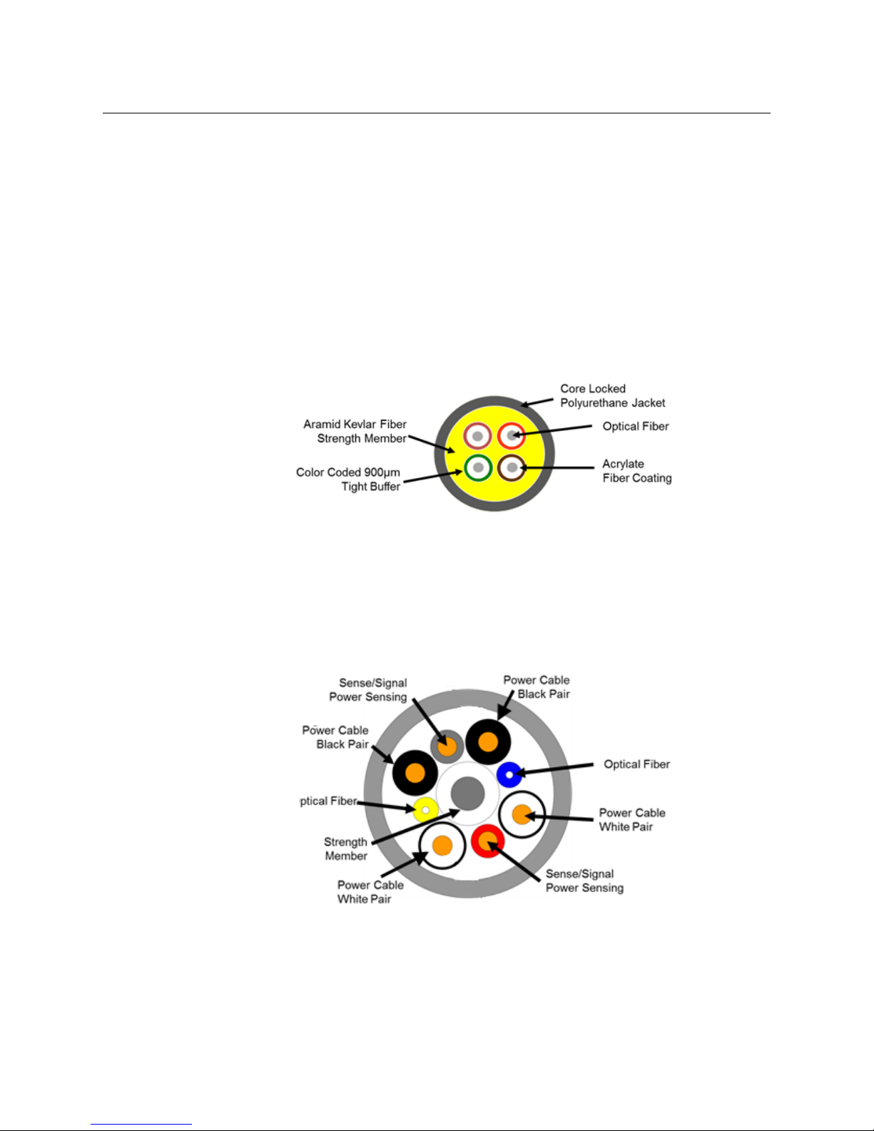
Hybrid Fiber Cable has the same Fiber Optic characteristics with the addition of copper
cables. This allows the transmission of power through the cable.
Fig. 2-2: Hybrid Fiber Optic Cable Cross-section
Thisincreasesweightandreducesoperatingdistance.HybridFiberCablealsoincludesa
pairofSense/Signalwiresthatallowsystemstodetermineifthereisanopenorshorted
cable.HybridFiberCableisalsolargerindiameterthenTacticalFiberCable.

7
CopperHead 3400
User Guide
Fiber Optic Connector Types
Depending on the type of Fiber Optic Cable used, different Connector types can be
configured. The following table summarizes the various types of connectors typically used
in a CopperHead 3400 configuration and the allowed Fiber Optic Cable usage. Each
connector type is illustrated below.
Fig. 2-3: Fiber Optic Connectors
ConnectorType
Tactical
FiberUse
Hybrid
FiberUse
Camera
UnitUse
Base
StationUse Notes
ST Fiber Connectors Yes Not
Typically
No Yes Less Expensive – not as durable as
OpticalCON, SMPTE 304M or MX
ST Fiber Connectors
with Molex Power Plug
No Not
Typically
No Yes Used with separate Fiber and Power
cables
LC Connectors No No No No Infrastructure and Internal Equipment
Use
SMPTE 304M No Yes (up
to 95V)
Yes Yes
OpticalCON Cable
Connector (Neutrik)
Yes Yes Yes Yes
OpticalCON Panel
Connector (Neutrik)
Yes Yes No No Infrastructure Use Only
MX Expanded Beam
Connector
Yes No Yes Yes
ST Cable
Connectors
ST Panel
Connectors
ST Panel w/
Molex
OpticalCON
Cable
OpticalCON
Panel
LC Connectors SMPTE 304M
Cable
SMPTE 304M
Panel
MX Expanded
Beam Cable
MX Expanded
Beam Panel

8
System Overview
CopperHead 3400 Transceiver System concepts
CopperHead 3400 Transceiver System concepts
The CopperHead 3400 is a camera video, audio, and data-multiplexing system that is
installed between a portable video camera and its power source. It connects via a single
fiber optic cable to a Base Station in a truck, studio, or other video production setup.
All video, audio, and data usually carried on Triax or multi-core cable is sent, bi-directionally,
over a single lightweight fiber over distances as long as 5 km or more. The CopperHead
3400 is specifically designed to support the use of 3D or Dual-Link camera setups.
The Camera Unit fits between the battery or optional power supply and the camera. The
CopperHead Camera Unit is configured at time of purchase with special interface plates to
accommodate the appropriate camera battery type.
The camera Battery or optional power source attaches to the Camera Unit, which in turn,
attaches to the video camera. Batteries accommodated are Sony V, PAG, and Anton-Bauer.
The CopperHead 3400 consists of two main components:
•The CopperHead 3400 Camera Unit – this unit has two options:
• the battery physical interface system
• the fiber connector
•The CopperHead 3400 Base Station – this unit has three options:
• the power configuration
• the fiber connector
• the intercom module
Typically options are determined at the time of product order and the units are delivered
pre-configured. Options can be field-changed by qualified personnel. This manual
describes each of the possible options.

9
CopperHead 3400
User Guide
Signal paths in the CopperHead 3400 Transceiver System
The CopperHead 3400 utilizes an optical fiber link between the Base Station and the
Camera Unit to carry all of the required signals necessary for operation of the camera and
associated production equipment. The Camera Unit multiplexes electrical signals from the
camera and other remote sources and converts them to an optical signal for transmission
over the fiber.
Simultaneously, an optical return signal is received at the Camera Unit from the Base
Station, which is then converted to electrical analog information for use by the camera,
camera operator, and auxiliary equipment at the camera location.
Fig. 2-4: Base Station to Camera Unit Connection
When the hybrid fiber cable option is used, the link also provides power to the Camera Unit
and the camera itself. Only the single fiber link or hybrid fiber link is required between the
Base Station and the Camera Unit.

10
System Overview
CopperHead 3400 Transceiver System Components
CopperHead 3400 Transceiver System Components
Camera Unit Overview
Fig. 2-5: Camera Unit, Front and Rear
The actual appearance of your CopperHead 3400 Camera Unit will vary depending on the
battery mount and fiber cable connection options specified at the time of purchase.
Base Station Overview
Fig. 2-6: CopperHead 3400 Base Station Connector, Front and Back Panel
The actual appearance of your CopperHead 3400 Base Station will vary depending on the
fiber cable connection and power options specified at the time of purchase.
CameraUnitFront
(attachestothecamera)
CameraUnitRear
(attachestothebatteryorpowersupply)
Front Panel
Back Panel

11
CopperHead 3400
User Guide
Transceiver System Additional Components
In addition to the CopperHead 3400 Camera Unit and Base Station, the system consists of:
• External Power Supply or Power Cord for the Base Station (depending the unit
configuration)
• Cable Sets as required by your camera and remote controller types to connect the
CopperHead Camera Unit to the camera, and to connect the Base Station to the
optional remote controller
• Hardware kits for rack mounting the Base Station
• Portable fiber reel with fiber per your purchase order
• Optional “Power Wafer” Camera Adaptor with optional external power supply
• Optional “PowerPlus” Camera Adaptor and Power Adaptor
• Optional Universal Camera Control Unit
For additional accessories see Available Accessories on page 96,
Note: You must use your own cables to make connections for Tally, Black Burst/Gen
Lock, Base Station monitor, and other ancillary signals and equipment. See Multi-Pin
Connectors: Suggested Wiring on page 92 for suggestions.

12
System Overview
Transceiver System Additional Components

13
Component Detailed Description
This chapter describes in detail each element on the Camera Unit and Base Station of the
CopperHead 3400. Physical installation of the system and system connections and practical
operation are covered in following chapters.
For an overall view of component locations, see the CopperHead 3400 overall diagrams in
CopperHead 3400 Base Station Back Panel on page 107.
Camera Unit . . . . . . . . . . . . . . . . . . . . . . . . . . . . . . . . . . . . . . . . . . . . . . . . . . . . . . . . . . . . . . . . . . . . . . . . . 14
Base Station . . . . . . . . . . . . . . . . . . . . . . . . . . . . . . . . . . . . . . . . . . . . . . . . . . . . . . . . . . . . . . . . . . . . . . . . . . 25
Additional CopperHead 3400 Transceiver System Items . . . . . . . . . . . . . . . . . . . . . . . . . . . . . . . 34

14
Component Detailed Description
Camera Unit
Camera Unit
Camera Unit Front Components
Fig. 3-1: CopperHead 3400 Camera Unit Front Side
The front side of the Camera Unit has five features:
•A - Connector Panel, see Area A – Connector Panel on page 21
•B- Camera Mounting Plate, see Area B – Camera Mounting Plate on page 15
•C - Signal/Data LED Activity Indicators, see Area C – Signal/Data Indicators on page 16
•D- Digital Status Display & Power Switch, see Area D - Optical Link Signal Strength
Indicator & Power Switch on page 18
•E - Fan Control Switch and Indicators, see Area E – Fan Control Switch and Indicators
on page 19
Other manuals for CopperHead 3400
1
Table of contents
Other Telecast Transceiver manuals


