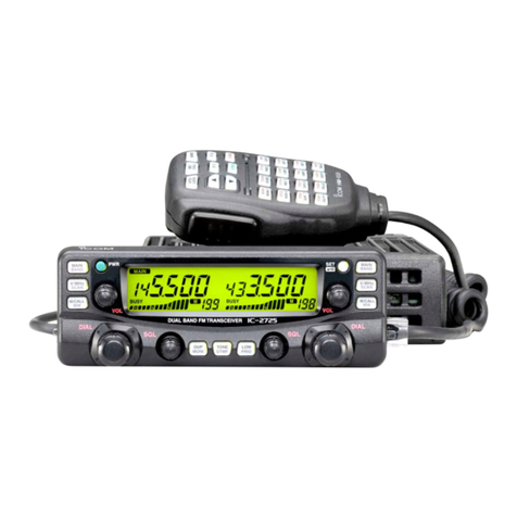
Icom IC-821H User manual

VHF/UHF
ALL MODE TRANSCEIVER
IC-B21H
learn Inc.

INTRODUCTION
This
......
"'
.....
ldl!:>i:
:Ilhelalesl
seMce
illoom
irlllllot
the
le·82
1H
VHflUHF ALL MODE
TRANSCEIVER.:
the
6,..
01
pubIicaIion.
To upgrade qual
it1.
any
el.c~W
0<
me<:hanCal
1>'1'11
8<>d
inWnaI
~;n;I>II.
ate
,ubi"'"
to
change
wil
lIout Mlice o.
~;gat;on.
ORDERING PARTS
ee
5
U'
.
10
include
Ih
e (,"l
ow
ing
(OU
, poinl' when
o<d
erinij
r~",*""
nl
pa~"
I.
lo-digil
O<det
n"",b.n
2.
c...,
....
"."t
poan
numbe<
8<>d
name
3.
Equipment
model name
and
....
~
"""'"
4.Ouanbly
"",.qd
<S
AM
PLE ORDER:>
s..::
"-_
~lH
......,.
.....-r
$ _
_
FHW
. U K
~lH
Tq>
....
10_
""
d'""1
ar
e
p'oYkIeo
on
tl\e il\$ide
Moc
k
~,
tor
)'OU'
con
.
e".o"ce.
DANGER
I'IeVeR
(;()nl8Cl
lhe
lIal'll<:eno,.
10
an
AC
outle1
01'
10
a DC
po
_ supply thai
uses
/IIOfe than
1«1
V. Th,
.....
1ruin
the
Itam+
',
..
.
DO
I'I
OT (!lipase
!he
tfansceMlf
10
..
...
__
01'
any:q
.....
DO
NOT '
......
u lhe
f>Ola'
i
liet
01
l
ilt
POWe' . u
p;>!,
wilen
connecting
the tfansceiv
..
DO
I'IOT
IIPPIY
an
RF
....,31
01
more
Ih
an
20
dam
II
00
mWl
to
t
ilt
an:enna
coone<:lo<.
This could
da"'age
the
I ,
a
n
~
er"
1'001
end.
REPAIR NOTES
I.
Mak
e
.",e
a p«)blem is i
nl
em
al
belo<
e
d
;
salll~
mbl
i
ng
!he
lra
n
~
.
2.
DO I'IOT 0!lI'" t
he
Uansceiv
e'
un
lil
(
he
tl
an_i,e
, is
disconnec\ed
Irc.-n
i
lS
power
soun::e.
3.
00
NOT
fon::e....,.,..
0I1he
,ariab!e
00I';"',,,_
••
,1S.
T
um
1I>em
~ard
..
'IO<lIi~".
•.
OOl'lOTshottanyC>-CUlso<elec\t(lnCl*\I.
M~
1unong
tool MUST
tNt.-
tor
..
....,
__
.
S. DO N
OT
k
ee:>
POW"
ON
fo<
• long time
..
hen
the
".,,,,,
,
'",
is d,.:
:r
....
6.
00
NOT
\r.ItI$fM
pOWef
inIo
a sq.aI
goII'*alOl'
0<
a
...
IIP
--
7.
A~WA
VS
connec! a 50 dB10
eo
dB aHenualo<
be
:..
e,,,
!hetr..-..ceivet and adeviatioomelet
Ot
specltvm~
..
_
using
suc/11e51
equipment
.
8.
READ
the
instn>el
ioo.
01
t
e&
1equiprl'le
nl
V
\C<O\9"
~
before
connec
ti
11\1
equi
pment
to
lloe
tr
ansceiver.

TABLE
OF
CONTENTS
SECTION 1 SPECIFICATIONS
SECTION 2 DISASSEMBLY INSTRUCTIONS
SECTION 3 INSIDE VIEWS
SECTION 4 CIRCUIT DESCRIPTION
4 - 1 RECEIVER CIRCUITS ...................................................................................................................................4 - 1
4 - 2 TRANSMITTER CIRCUITS ............................................................................................................................4 - 4
4-3
PLLCIRCUITS ...............................................................................................................................................
4-6
4 - 4 POWER SUPPLY CIRCUITS .........................................................................................................................4 - 7
4 - 5 PORT ALLOCATIONS....................................................................................................................................4 - 7
SECTION 5 ADJUSTMENT PROCEDURES
5
-1
PREPARATION BEFORE SERVICING .........................................................................................................
5-1
5 - 2 PLL ADJUSTMENT ........................................................................................................................................5 - 2
5 - 3 FREQUENCY ADJUSTMENT ........................................................................................................................5 - 2
5 - 4 RECEIVER ADJUSTMENT ............................................................................................................................5 - 4
5 - 5 TRANSMITTER ADJUSTMENT .....................................................................................................................5 - 8
5 - 6 METER AND SQUELCH ADJUSTMENT.....................................................................................................5
-12
5 - 7
RF
METER ADJUSTMENT ..........................................................................................................................5 - 13
5 - 8 METER REFERENCE ADJUSTMENT.........................................................................................................5 - 13
SECTION 6
PARTS
LIST
SECTION 7 MECHANICAL
PARTS
SECTION 8 SEMI-CONDUCTOR INFORMATION
SECTION 9
BOARD
LAYOUTS
9 - 1 FRONT ...........................................................................................................................................................9 - 1
9 - 2 MAIN UNIT .....................................................................................................................................................9 - 4
9 - 3 PLL UNIT ........................................................................................................................................................9 - 6
9 - 4 PA-A AND PA-B UNITS .................................................................................................................................9 - 7
9 - 5 RF-A AND RF-B UNITS..................................................................................................................................9 - 8
SECTION
10
BLOCK
DIAGRAM
SECTION
11
VOLTAGE
DIAGRAM

SECTION 1 SPECIFICATIONS
• GENERAL • RECEIVER
• Frequency coverage:
Version 144 MHz band 440 MHz band
Rx:
136.0-174.0
MHz*
U.S.A
430.0-450.0
MHz
Tx:
144.0-148.0
MHz
Europe
144.0-146.0
MHz
430.0-440.0
MHz
Australia
144.0-148.0
MHz
430.0-450.0
MHz
Sweden
144.0-146.0
MHz
432.0
-438.0
MHz
*Guaranteed frequency range IS
144.0-148.0
MHz
• Mode SSB (J3E), cw (A1A),
FM
(F3E)
• Number of memory: 160 (80 channels for each band)
channels
• Antenna connector: VHF SO-239 (50
Q)
UHF Type-N (50
Q)
• Usable temperature: -10°C to +60 t : +14
of
to +140
of
range
• Frequency stability :
• Tuning steps
• Power supply
requirement
• Current drain
(at 13.8
V)
• Dimensions
• Weight
±3 ppm ( - 10°C
to
+60°C )
SSB, CW
1,10,50
or 100 Hz
FM
0.1
,
5,
10, 12.5, 20, 25 or
100 kHz
13.8 V ±15 % (negative ground)
Transmit Max. power 16.0 A
Receive Stand-by 2.0 A
Max. audio 2.5 A
241
(W) x 94 (H) x 239
(D)
mm
9.5 (W) x 3.7 (H) x 9.4 (D)
in
(projections not included)
5.0
kg;
11.0
Ib
• TRANSMITTER
• Output power 144 MHz SSB
6-35
W
FM,
CW
6-45W
440 MHz SSB
6-30
W
FM, CW
6-40W
(continuously adjustable)
• Modulation system : SSB Balanced modulation
FM
Variable reactance mod.
• Suprious emission : Less than -60 dB
• Carrier suppression: More than 40 dB
• Unwanted sideband: More than 40 dB
• Microphone 8-pin connector (600 Q)
connector
• Key connector 3-conductor 3.5
(d)
mm (1/8")
• Receive system
144 MHz band
SSB, CW
FM
440 MHz band
Single conversion superheterodyne
Double conversion superheterodyne
SSB, CW Double conversion superheterodyne
FM
Triple conversion superheterodyne
• Intermediate frequencies (unit: MHz)
MAIN BAND SUB BAND
MODE
~---r----.----4----.-----r---~
1st
2nd
3rd
1st
2nd 3rd
SSB 10.8500 10.9500
IL.
....................................................................
.
X
> CW 10.8491 10.9491
...
__
.........................................................................................
FM 10.8500 0.4550 10.9500 0.4550
SSB 71.2500 10.8500
71.3500
10.9500
IL.
...................................................................
.
X
~
CW 71.2491 10.8491 71.3491 10.9491
FM
71.2500 10.8500 0.4550 71.3500 10.9500 0.4550
• Sensitivity (both VHF and UHF bands)
SSB, CW
0.11
IlV for
10
dB
SIN
FM
0.181lV for 12 dB SINAD
• Squelch sensitivity (both VHF and UHF bands)
SSB, CW Threshold Less than 1.0
IlV
Tight Less than 3.2 mV
FM
Threshold Less than
0.1
IlV
• Selectivity
SSB, CW
CW
narrow
(optional)
FM
• Spurious and image:
rejection ratio
• Audio output power:
(at 13.8 V
DC)
• IF shift variable
range
• RIT variable range
SSB,
CW
FM
• External speaker
connector
Tight Less than 3.2 mV
More than 2.3
kHz/-6
dB
Less than 4.2
kHz/-
60
dB
More than 0.5
kHz/-6
dB
Less than 1.34
kHz/-
60 dB
More than 15.0
kHz/-
6 dB
Less than 30.0 kHz/-
60
dB
More than 60 dB
More than 2.0 W at 10 %
distortion with
an
8 Q load
More than ± 1.2 kHz
More than ±1.0 kHz
More than ±5.0 kHz
2-conductor 3.5 (d) mm
(1/8")
/8
Q
x 2 (for MAIN and SUB bands)
All
stated
specifications
are
subject
to
change
without
notice
or
obligation.
1
-1

SECTION 2 DISASSEMBLY INSTRUCTIONS
•
Opening
the
transceiver's
case
CD.
Unscrew 8 screws from the transceiver's top and 4 screws
from the sides, then remove the top cover.
® Turn the transceiver upside down.
® Unscrew 4 screws from the bottom cover, then remove the
bottom cover.
•
Opening
the
inside chassis
CD
Remove the top and bottom covers as shown above.
® Loosen the gutter screw on each side of the front panel's
rear side.
® Unscrew t screw from each side of the front panel's rear
side.
® Pull the front panel forward as shown by the arrow at right.
® Loosen 1 flat head
screw
each side
of
the MAIN unit
chassis.
® Unscrew 2 silver screws from the rear panel.
(j) Lift and pivoted the MAIN unit
chassis
to the vertical
position, and tighten the screws (labelled
®)
to secure the
chassis.
2
-1
•
Removing
the
PA-A
unit
CD
Opening the inside chassis as previous instructions.
® Unscrew 8 silver screws ®, then remove the PA-A cover.
® Unsolder 3 points
®.
® Unscrew 2 screws
®.
® Unscrew 6 silver screws
®,
then remove the PA-A unit.
•
Removing
the
PA-B
unit
CD
Remove the top cover.
® Unscrew 8 silver screws
®,
then remove the PA-B cover.
® Unsolder 3 points
®.
® Unscrew 2 screws
®.
® Unscrew 2 screws
®.
® Unscrew 8 silver screws
®,
then remove the PA-B unit.
rv
I

SECTION 3 INSIDE VIEWS
• MAIN UNIT ,
~N
•
• -
• !
:i:~
.-
-"
, - '" !
~ , .
•
~~
0
• •
• ,
<
,
,
,
~~
,"
,-
•
--
i·
.
I~
0 -
•• •"
~~
-"
0
,.
ft
,
, -
S'~
d
"

• RF·A, RF·B AND
PA
·B
UNITS
,
,
(0I,:2S><2
171
1
012:2S><2'1\
Ioeolod
.-.
_
of
....
se1>O<>l.
: I I
• PA·A AND PLL UNITS
P
ow«
m:><Mo
------
IIC2: SC-I \ \3)
(IC'
:SC
·
11
14)
,
,
1011
:
2SI<508)
Io<;.alod""'-
,do
of
,
...
1>0<>1
IX
1:
CR-
452
30
.2 MHl)
-
----
Co
,
DDS
cfl;C",
f-------
,~
DDSoO-euil

SECTION 4 CIRCUIT DESCRIPTION
4-1
RECEIVER CIRCUIT
Note: [Main]=Main band, [Sub]=Sub
band
4-1-1 VHF ANTENNA SWITCHING CIRCUIT
(PA-A UNIT)
Received signals from the antenna connector
(J2)
are
passed through the low-pass filter (L3-L5, C5-C8) then
applied
to
the antenna switching circuit
{01-03,
L6.
L7}.
The antenna switching circuit functions as a low-pass filter
while receiving. However, its impedance becomes very
high while transmitting by turning
ON
diodes (02, 03).
Thus transmit signals are blocked from entering the receiver
circuits.
The passed signals are then applied to the RF-A unit.
4-1-2 VHF RF CIRCUIT (RF-A UNIT)
Received signals from the PA-A unit via J6 are applied
to
the
RF
amplifier circuit
(Q7)
via the
RF
attenuator (015)
and
tunable bandpass filter (013. L16) circuits.
The amplified signals are then passed through the another
tunable bandpass filter circuit (010-012, L
13-L
15) to sup-
press unwanted signals. The filtered signals are then
applied
to
the 1st mixer circuit
(Qll
,Q12).
Varactor diodes (010-013) are used for the bandpass
filters
to
tune the center frequency for wide bandwidth
receiving
and
good
image response rejection. PLL lock
voltages are applied
to
these diodes for tuning.
4-1-3 VHF 1STMIXER CIRCUIT (RF-A UNIT)
The 1st mixer circuit converts the received signals to a fixed
frequency of the 10
MHz
IF signal with a PLL output fre-
quency.
By
changing the
PLL
frequency, only the desired
frequency
will
be
passed through a pair of crystal filters at
the next stage of the VHF 1st mixer.
• RECEIVER CONSTRUCTION
440 MHz PA unit:RF·B unit
014.015
4
-1
The filtered signals from the bandpass filter are mixed with
1st
LO
signals at the mixer circuit
(Ql1,
Q12) to produce a
1st IF signal (10.85
MHz
[Main] or 10.95
MHz
[Sub]). The
1
st
LO
signals are the PLL output frequency which comes
from the VHF
veo
circuit (PLL unit.
Q1.
01-03,
08).
The 1st IF signal is then applied to either the Main or Sub
band
10
MHz
IF circuit
in
the
MAIN
unit via
P1
[Main] or
P2
{Sub].
4-1-4 UHF
RF
CIRCUIT (RF-B UNIT)
The received signals from the UHF antenna connector are
passed through the low-pass tilter (PA-B unit, L3-L5,
C5-C10)
and
then the antenna switching circuit (PA-B unit,
01-03).
The signals from the antenna switching circuit are
then applied
to
the
RF
amplifier circuit (Q16) via the tunable
bandpass filter (014,
L35)
and
RF
attenuator circuit {016}.
The amplified signals are passed through the tunable band-
pass filter (011-013),
and
then applied
~o
the 1
st
mixer
circuit
(Q14,
Q15).
4-1-5 UHF 1STAND 2ND MIXER CIRCUIT
(RF-B UNIT)
The filtered
RF
signals from the bandpass filter are mixed
with
a 1
st
LO
signal at the 1st mixer circuit
(Q14,
Q15)
to
produce a 1st IF signal (71.25
MHz
[Main] or 71.35
MHz
[Sub]). The 1st IF signal is passed through a crystal filter
(F12
[Main),
Fll
[Sub])
to
suppress out-ot-band signals. The
filtered
IF
signal
is
then applied
to
the
2nd
mixer circuit
(Qll)
to
produce a 10
MHz
IF signal with a
2nd
LO
signal.
The IF signal is then applied
to
the
MAIN
unit via
P1
[Main]
or
P2
[Sub].
The 1st
LO
signal is generated at the UHF
VCO
circuit (PLL
unit,
Q5,
04, 010), and the multiplied reference signal
is
used for the
2nd
LO
signal.
I
MAIN
unit
I
I
I
I
BFO
for
MAIN
band
AF
signals to
SOL
control circuit
tor
SUB
band
AF signals to SOL
control circuit
10.9483-10.9515 MHz
to FM IF IC (IC20)
4-1-6 10 MHz IF CIRCUIT (MAIN UNIT)
The 10
MHz
IF signal from the mixer circuit
is
passed
through the bandpass filter (FI2 [Main], FI6 [Sub]) to sup-
press out-of-band signals. The filtered signal
is
amplified
at
the
IF
amplifier (013 [Main],
098
[Sub]). The IF amplifier
provides 20
dB
gain.
The amplified signal
is
then applied to different circuits
depending
on
the selected mode.
(1)
FM
mode
The signal
is
applied to
an
FM
IF
IC
pin
16
(IC11
[Main]
or
IC20 [Sub]).
(2) SSB and CW mode
The signal
is
passed through a 10
MHz
IF
filter
(FI1
/1
0.85
MHz
[Main] or FI5/10.95 MHz [Sub]) or optional
CW
narrow
filters. The filtered signal
is
amplified at the IF amplifiers
(060-062
[Main] or 077. 0100. 0101 [Sub]) and then
applied to a demodulator circuit.
4-1-7 DEMODULATOR CIRCUIT (MAIN UNIT)
(1)
FM
mode
The 10
MHz
IF
signal from
an
IF
amplifier (013 [Main]
or
098
[Sub])
is
applied to the mixer section of the
FM
IF
IC
(IC11
[Main], IC20
[Sub).
pin
16)
and
is
mixed with a
lO
signal (10.395
MHz
[Main). 10.495
MHz
[Sub])
to
produce a
455
kHz
IF
signal. The
lO
signal
is
generated
by
the
BFO
circuit
(IC1
01
[Main], IC103 [Sub])
The
FM
detector circuit employs the quadrature detection
method. which uses a ceramic discriminator
(X2
[Main],
X4
[Sub]) for phase delay to obtain a non-adjusting circuit.
The detected signals are output from
pin
9,
and
applied to
the squelch control
and
center indication detector circuits.
etc.
(2) SSB and
CW
modes
The
amplified signal from the
IF
amplifier circuit (062
[Main]. 0101 [Sub])
is
applied
to
the balanced mixer circuit
(IC14 [Main]. IC22 [Sub]) to demodulate into
AF
signals.
Demodulated audio signals are output from
pin
3,
and
applied
to
the squelch control gate (IC16 [Main]. IC28
[Sub]).
• AF
circuit
IC14
Demodulator
[MAIN band]
BFO
circuits
(IC101
[Main]
and
IC103 [Sub]) generate
BFO
signals for use
in
the balanced mixers.
• BFO frequencies
Mode
for
MAIN band
for
SUB band
USB
10.8485 MHz 10.9485 MHz
lSB
10.8515 MHz 10.9515 MHz
CW
10.8483 MHz 10.9483 MHz
4-1-8 SQUELCH CONTROL CIRCUIT
(MAIN UNIT)
The demodulated
AF
signals from the balanced mixer
circuit or
FM
IF
IC
are applied to the squelch control gate
(IC16 [Main), IC28 [Sub]). This consists of 4 analog
switches which are selected with a mode signal
and
squelch
control signal from the
CPU
(DISPLAY unit, IC1) via the
expander
IC
(IC8 [Main], IC24 [Sub]). The switched
AF
signals are applied to the AF circuit.
4-1-9 SQUELCH CIRCUIT (MAIN UNIT)
(1)
FM
mode
A squelch circuit cuts out
AF
signals when
no
RF
signal
is
received or the S-meter signal is lower than the [SOL]
control setting level.
By
detecting noise components
in
the
AF
signals, the
CPU
switches the squelch control gate.
Some noise components
in
the
AF
signals from
pin
9 of the
FM
IF
IC
(IC11
[Main], IC20 [Sub]) are applied to the active
filter section
(pin
10) of the
FM
IF
IC.
The filtered noise
components are output from pin
11
, and then applied
to
the
noise detector circuit
(D35
[Main],
D55
[Sub]) for conversion
into
DC
voltages. The voltages are then applied to the
buffer-amplifier (IC116 [Main], IC118 [Sub]).
The buffer-amplified
DC
voltages are applied to the
CPU
(DISPLAY unit. IC1) via the ADMNO [Main]/ADSNO
[Sub]
line. The
[SOL]
level signal
is
also applied to the
CPU
via
the gate control circuit (DISPLAY unit. IC11)
as
a reference
voltage for comparison with the noise signals. Also,
an
S-meter signal is applied to the
CPU
from
FM
IF
IC
pin
13
(IC11
[Main], IC20 [Sub] via the meter amplifier (IC15a
[Main], IC23b [Sub]). The
CPU
compares these signals.
then outputs a control signal to the squelch control gate.
JACK board MSP SSP
AFMM IC32
rnrn
11
------------------------
IC22 [SUB band] 7
Demodulator
AFMS
4-2

(2) SSB and
CW
modes
The squelch circuit mutes audio output when the S-meter
signal
is
lower
than
the
[SOL]
control setting
level.
A portion of the 10
MHz
IF signal from the IF amplifier (062
[MainJ.
0101 [Sub])
is
converted into
DC
voltage at the
AGC
detector (044.
065
[Main]. 073. 0104
[Sub))
and
meter amplifier (IC15b [Main]
or
IC23a
[Sub)).
The ampli-
fied
signal
is
applied
to
the
CPU
(DISPLAY unit. IC1) via the
ADMSM
[Main]/ADSSM [Subjline. The
CPU
outputs con-
trol signals
to
the squelch control gate
when
the S-meter
signal
is
low level.
4·1·10
AF
AMPLIFIER CIRCUIT (MAIN UNIT)
The
AF
amplifier circuit amplifies the demodulated signals
to drive a speaker. For the separate speaker function. a
stereo power amplifier
is
used.
AF
signals from the squelch control gate
are
amplified
at
the voltage controlled amplifier
(VCA;
IC30 [Main].
IC31
[Sub]) which functions
as
a volume control using the
[AF]
control signal. The amplified
AF
Signals
are
applied
to
the
AF
power amplifier circuit
(IC32.
pin
2 [Main].
pin
5 [Sub]).
The
amplified audio signals of
SUB
band
are output from
from
pin
7I
and
are applied
to
the external speaker jack for
the
SUB
band
(J17) via the
[PHONE]
jack (JACK board,
Jl).
When
no
plug
is
connected
to
the jack. the signals are
fed
back
to
the
MAIN
band
audio input (IC32,
pin
2)
and
combined
with
the
MAIN
band
audio. The
mixed
audio
is
applied
to
the internal speaker via the
[PHONE]
jack
and
external speaker jack for the
MAIN
band (J16).
4·1·11 NOISE BLANKER CIRCUIT
(MAIN UNIT)
The
noise blanker circuit detects pulse-type noises,
and
stops IF amplifier operation during detection.
• AGC and Noise Blanker circuits
FI2
[F16)
IF signal
013
(098)
Fl1
[F15)
060
(077)
4-3
A portion of the
10
MHz
IF
signal from the bandpass filter
(F12
[Main], FI6 [Sub])
is
amplified at the noise amplifier
circuit (07. IC6,
09
[Main], 0252, IC119,
0254
[Sub]). The
amplified signal
is
rectified
at
the noise detector circuit for
conversion
Into
DC
voltage. The
DC
voltage
is
amplified
at
the
DC
amplifier circuit (011,
012
[Main], 0256.
0257
[Sub))
and
then applied to the noise blanker control circuit
(014
[Main].
0212
[Sub]) to
stop
amplification of the IF
amplifier circuit (013
[Main].
098
[Sub)).
Some
DC
voltage
is
fed back to the
nOise
amplifier circuit
(IC6
[Main].
IC116
[Sub))
via the
DC
amplifiers (08,
010
[Main]. 0253, 0255 [Sub]). The
DC
amplifiers function
as
an
AGC
circuit to reduce averaged noise. Therefore. the
noise blanker function shuts off pulse-type noise only.
4-1-12 AGC CIRCUIT (MAIN UNIT)
The
AGC
(Auto
Gain
Control) circuit reduces IF amplifier
gain
to
keep
the audio output
at
a constant level.
A portion of the 10
MHz
IF signal from the IF amplifier (062
[MainJ.
0101
[Sub})
is
applied to the
AGC
detector circuit
(044
[Main].
073
[Sub}).
The detected signal
is
then
amplified
at
the
DC
amplifier circuit (065 [Main]. 0104
[Sub])
and
then
applied
to
the IF amplifiers (013. 061.
062
[Main]. 098, 0100, 0101 [Sub]).
When
strong
signals
are
received, the detected voltage
increases
and
the output level of the
DC
amplifier,
as
AGC
voltage, decreases. The
AGC
voltage
is
used for the bias
voltage for the IF amplifiers. therefore. the IF amplifier gain
is
decreased.
AGC
response time is controlled by changing the time
constant
at
the
AGC
control line with a resistor (R276
[Main].
R432 [Sub])
and
capacitors
(C206.
C210
[Main).
C381.
C385 [Sub]). These are connected
to
the
AGC
control line
While
AGC
is
set
to
slow.
However, R276
and
C210 [Mainj/R432
and
C385 are disconnected from the
AGC
control line while
AGC
is
set
to
fast. due
to
067
and
068
[Main}/0105
and
0210
[Sub}
being switched OFF.
Also,
C206
[MainJ/C381
[Sub]
is
disconnected from the
AGC
control line due to
054
and
055
[Main]/0206
and
0207
being
switched
OFF
while scanning for faster
re-
sponse
than
AGC
fast
mode
.
061
(0100)
062
IC7
[0101::;»
----4~~®
demodulator
circuit
AGe
amplifier
065
044
[0104]
[073]
.
iAGC
~
.....
Jdetector
+---------0
-5
V
]:
Sub band

4-1-13 S-METER CIRCUIT (MAIN UNIT)
The S-meter circuit indicates the relative received signal
strength while receiving
and
changes depending
on
the
received signal strength.
(1)
FM
mode
Some of the amplified IF signal
is
applied to the S-meter
detector section
in
the
FM
IF
IC
(lC11
[Main), IC20 [Sub)) to
be
converted into
DC
voltage. The converted signal
is
output from
pin
13
and
applied to the meter amplifier circuit
(IC15a [Main), IC23b [Sub)). The amplified signal
is
then
applied to the
CPU
(DISPLAY unit, IC1) via the ADMSM
[Main)/ADSSM
[Sub)
line. The
CPU
then outputs S-meter
drive signals
as
a METO signal.
(2) sse and
CW
modes
A portion of the
AGC
control signal
is
applied to the S-meter
amplifier. The amplified signal
is
then applied
to
the
CPU
to
drive the S-meter.
4-2 TRANSMITTER CIRCUITS
4-2-1 MICROPHONE AMPLIFIER CIRCUIT
(DISPLAY AND MAIN UNITS)
The microphone amplifier circuit amplifies audio signals
from the microphone or
ACC
connector
and
then applies
them
to
the modulation circuit. One microphone amplifier
circuit
is
commonly used for both FM/SSB
and
VHF/UHF.
Audio signals from the microphone are amplified at the
variable controlled amplifier (VCA; DISPLAY unit, IC3)
where the amplifier gain
is
controlled with the
[MIG)
control
setting.
The mic limiter circuit (029) activates when the
[COMP)
switch
is
turned
ON
to limit VCA output. The amplifier gain
is
also controlled with the [COMP
LEVEL)
control
in
such
cases. The amplified audio signals are then applied to the
other microphone amplifier circuit (IC2a)
in
the
MAIN
unit.
Audio signals from the
ACC
connector
is
amplified
at
IC2b.
These amplified signals from IC2a or IC2b are applied to
the IDC or the balanced mixer circuit depending
on
oper-
ating mode.
• SIGNAL CONSTRUCTIONS
IN
SATELLITE MODE
Example UHF receive / VHF transmit
MAIN band:
Rx
SUB band: Tx/Rx
433.000.0
VHF UHF I
I
I
lh~
145.000.0
!MAIN
unit
I
I
RF-B unit
~-t-""'\
I I
L
~.-.-.-.-.-.-.I
I
4-2-2 MODULATION CIRCUIT (MAIN UNIT)
(1)
FM
mode
The amplified audio signals from IC2a are pre-emphasized
and
limited at
IC1
b
and
then passed through the splatter.
filter
(IC1
a).
The filtered signals are then applied to the
FM
modulation circuit (022) via the
FM
deviation adjustment
pot (R29). Also, subaudible tone signals from the BFO
circuit
(IC1
01) are applied to the
FM
modulation circuit via
the tone deviation adjustment pot (R64).
The
FM
modulation circuit changes the generating fre-
quency of the
FM
local oscillator (017,
X1)
to generate
an
FM
signal. The modulated IF signal
is
passed through the
transmit gain control pot (R136)
and
then applied
to
the
transmit IF amplifier circuit.
When 9600 bps mode
is
selected, audio signals from the
ACC
connector bypass the amplifiers
and
are applied
to
04
directly via the external modulation switch (MAIN unit,
IC114, pins
1,
7).
In
such cases, the modulation limiter
(IC17) cuts off the audio line when overmodulation
is
detected.
(2) sse mode (MAIN
unit)
The amplified audio signals from IC2a are mixed with BFO
signals
at
the balanced mixer circuit (IC7) to produce a 10
MHz IF signal. The mixed signal
is
still a
DSB
signal,
therefore, the mixed signal passes through bandpass filter
circuit (FI1) to suppress unwanted side band signals. The
filtered signal
is
applied to the transmit IF amplifier circuit.
Mode
Transmit
IF
signal
USB 10.8485 MHz
LSB
10.8515 MHz
CW
10.8491 MHz
4-2-3 CW KEYING CIRCUIT (MAIN UNIT)
Keying signals (EDOT and EDSH) from the
[KEY)
jack (J19)
are applied
to
the
CPU
(DISPLAY unit, IC1),
and
the
CPU
outputs
an
EKEY signal to the
CW
break-in circuit (0234,
084).
The signal output from the
CW
break-in circuit
is
applied to the
BFO
mute switches (0120, 0121) to cut the
BFO
signal line while releasing. While keying, BFO signals
are applied to the balanced mixer,
and
a
DC
bias voltage
is
applied
to
leak carrier signals.
"W....
[SUB VOL)

The output signal from the
CW
break-in circuit
is
also
applied
to
the CW side-tone generator circuit (Q80, Q81).
4·2·4 TRANSMIT IF AMPLIFIER CIRCUIT
(MAIN UNIT)
The
modulated
IF
signal from a modulation circuit is applied
to
the IF amplifier circuit (Q1). The amplified IF signal is
then applied to the RF-A (during VHF) or RF-B (during
UHF) unit via the
V/U
switching circuit (018).
The
gain of the IF amplifier circuit (Q1)
is
controlled by the
ALC
amplifier circuit (IC3a). Therefore, the IF amplifier is
reduced when the output power increases.
4-2-5
RF
CIRCUIT (RF-A AND RF-B UNITS)
The
RF
circuit consists of mixer and drive amplifiers to
obtain the desired frequency
and
level needed
at
a
PA
unit,
respectively.
(1) VHF band (RF·A unit)
The IF signal
is
mixed
with
an
LO
signal from the VHF
VCO
circuit (PLL unit,
01,
01-03,
08) at the double-balanced
mixer circuit (01,
02)
to be converted into a VHF transmit
frequency. The mixed signal
is
then passed through the
tunable bandpass filter
(03-05)
to suppress spurious com-
ponents,
and
then amplified at the drive amplifiers (IC1,
Q4,
013)
to obtain
an
approx. 800
mW
output level.
The amplified
RF
signal
is
applied
to
the
PA-A
unit via J7.
(2) UHF band (RF·B
unit)
The IF signal
is
mixed with a 2nd
LO
signal at the double-
balanced mixer circuit (01,
02)
to produce a 2nd
IF
signal
(71.25
MHz).
The
2nd
LO
signal is generated at the
reference oscillator
and
multiplier circuit (PLL unit,
X1,
Q14)
via
LO
amplifier (IC2). The 2nd IF signal
is
amplified at the
buffer amplifier (03) via the bandpass filter circuit
(L3,
L4,
C12-C14, C164. C178, C179). The amplified
2nd
IF signal
is applied
to
the 1
st
mixer circuit (IC3).
The 1
st
mixer circuit converts the
2nd
IF signal into a UHF
transmit frequency
with
a 1
st
LO
Signal
from the UHF
VCO
circuit (PLL unit.
as,
04. 010). The converted
RF
signal is
amplified at drive amplifiers (IC1.
04,
aS) to obtain
an
approx. 200
mW
output level. The signal is then applied to
the
PA-B
unit via J3.
• APC and ALC
circuits
..
I
Bandpass filters (L36,
L37)
are designed between drive
amplifiers to suppress spurious components
in
the RF
signal.
4-2-6 POWER AMPLIFIER CIRCUIT
(PA-A AND PA·B UNITS)
The power amplifier circuit amplifies the
RF
signals to the
specified output power.
(1) VHF
power
amplifier
circuit
(PA-A
unit)
The
RF
signal from the RF-A unit is applied to the power
amplifier circuit (IC2). The amplified
RF
signal
is
applied to
the antenna connector
(J2)
via the power detector
(04-07,
L8),
antenna switching
(01-03)
and low-pass filter (L3-L5,
C5-C8) circuits.
(2) UHF power amplifier
circuit
(PA·B
unit)
The
RF
signal from the RF-B unit
is
applied to the drive
amplifier circuit (IC3) to obtain
4-5
W output level and then
applied to the power amplifier circuit (IC1). The amplified
RF
signal
is
applied to the antenna connector
(J1)
via the
power detector (04,
OS,
L9),
antenna switching
(01-03)
and
low-pass filter (L3-L5, C5-C10) circuits.
4-2-7 ALC CIRCUIT
(PA-A, PA-B AND MAIN UNITS)
The
ALC
(Automatic
Level
Control) circuit protects the
power module (PA-A unit, IC2 for VHF and
PA-B
unit.
IC1
for UHF) from a mismatched output load. Also, the
ALC
circuit controls the gain of the transmit IF amplifier
in
order
for the transceiver to output a constant
RF
power set
by
the
[RF PWRl control even when the supplied voltage shifts,
etc.
The
RF
power level is detected at the power detector circuit
(PA-A unit,
04-07,
L8
for
VHF,
PA-B
unit 04.
OS,
L9
for
UHF) to be converted into
OC
voltages. The detected
voltage (FORA for VHF or FORB for UHF) is applied to the
difference amplifier (MAIN unit, IC3a). A reference voltage
(POCO)
for IC3a
is
controlled
by
the [RF PWRl control
to
output difference voltages. The output voltage is applied to
the transmit IF amplifier circuit (MAIN unit, Q1) as
an
AALC
Signal
to control the amplifier gain.
to antenna connector
IF
signal I
APC~""""
.........•.......
:
I det. i i
I
iDS
04:
I
::
I
I'
-
0::-
:Current:
I
'0::
':
OS:
I RF·A unit I
~
......••.•••.
.idet. _
..•••......................
-MAIN-
u-;"ii
-
-'C4b
--
~
-----
-!
<
'--
____
--1~7<
APC
HVF .
~
PA-A unit
!-------------IC1-f~~
PA.S
------
-u..
--------
I------------+--
FORB from PA·B
1'----"1'111<::-1
[RF
PWRl
control
4-5

When the FORA/FORB voltage increased, the output from
the difference amplifier will
be
decrease
to
reduce the IF
amplifier gain. This adjusts the
RF
output power until the
FORA/FORB
and
POCO
voltages are well-balanced.
4-2-8 APC CIRCUIT
(PA-A, PA-B AND MAIN UNITS)
The
APC
(Automatic Power Control) circuit protects the
power amplifiers
on
the PA-A
and
PA-B units from exces-
sive current.
Current drain of power amplifiers
is
detected
by
voltage
drops
at
resistors (PA-A unit
R1,
R12
and
PA-B
unit
R1,
R16). The original voltage (IC1)
and
dropped voltage (AIC2
or
BIC2) are applied
to
the
APC
difference amplifier (MAIN
unit, IC4a or IC4b).
The signal output from the difference amplifier reduces IF
amplifier gain until these voltages are well-balanced.
4-3 PLL CIRCUITS
IC-821
H contains 2 PLL circuits
and
1 local oscillator. The
VHF
and
UHF PLL circuits adopt
"I
com's original I-loop
PLL" to obtain very fast lock
up
times.
• PLL circuits
ICl
IC2a
4-3-1
VHF PLL CIRCUIT (PLL UNIT)
The VHF PLL circuit generates the 1
st
LO
frequency,
and
the signals are applied
to
the 1st mixer circuits
in
the RF-A
unit. The PLL circuit consists of a VCO, prescaler
and
DDS
circuits.
The signal generated
at
the VHF
VCO
circuit (01, D1-D3,
D8)
is
amplified at the buffer-amplifiers (02, IC5), then
applied to the prescaler circuit (IC4). The prescaler circuit
divides the applied signal, and outputs it to the VHF
DDS
circuit (lC1) via the buffer-amplifier (04). The VHF
DDS
circuit generates digital signals using the applied signal
as
a
clock frequency. The phase detector section
in
ICl
com-
pares it's phase with the reference frequency which
is
generated at the reference oscillator (Xl).
IC1
outputs
off-phase components
as
pulse signals via pins
52, 53.
The output pulses are converted into
DC
voltage
at
the loop
filter circuit (IC2a)
and
then applied
to
the VHF VCO circuit.
The D/A converter (R15-R38), low-pass filter (L2-L4,
C4-C10)
and
buffer-amplifier (IC14) circuits are connected
to the
DDS
output to convert the digital oscillated signals
into smooth analog signals.
The output
DC
voltage from the loop filter circuit
is
also
applied to the RF-A unit to control the tuned bandpass filter.
IC2b
>---
To RF-A board
01,01-03,08
I--_-_l,r-~
..
~··~,'l-------A-l-L-O-
To VHF 1st mixer circuit
T
\..:l}
(RF-A board, 011,
012)
Xl: 30.2 MHz
L...-_--'
'
•.....•.......
_;
Prescaler
I---C
1/8
IC4
IC5 VHF PLL
circuit
r---------------------------
_________________________
..J
IC7b UHF PLL
circuit
-:>--_
To RF·B board
IC6
IC7a
05,04,010
I----+---:--~I
Phase
.--'---
__
1detector
1-'---1
Loop
filter
1----4
__
i:r-~
..
~
..
~;:'
___
--..~B:....l~L:....O_
To UHF 1st mixer circuit
T
\..:l}
(RF-B board, 014,
015)
'------'
'..............
_;
Prescaler
I---C
1/8
08
IC9
09
014
B2LO T UHF
d'
..
1-----------
________
0
2n
mixer
CircUit
(RF-B board,
011)
>----------
To
BFO
circuits (MAIN unit,
ICl
01,
IC103)
024
4-6

4-3-2 UHF
PLL
CIRCUIT (PLL UNIT)
The UHF PLL circuit generates the 1st
LO
frequency, and
the signals are applied to the 1st mixer circuits
in
the RF-B
unit. The PLL circuit consists of a VCO, prescaler and DDS
circuits.
The signal generated at the UHF VCO circuit (05,
D4,
D10)
is
amplified at the buffer-amplifiers
(06,
09),
then applied to
the prescaler circuit (IC9). The prescaler circuit divides the
applied signal, and outputs it to the UHF DDS circuit (IC6)
via the buffer-amplifier (08).
The pulses output from the UHF DDS circuit are converted
into
DC
voltage at the loop filter circuit (IC7a) and then
applied to the UHF VCO circuit.
The output
DC
voltage from the loop filter circuit is also
applied to the RF-B unit to control the tuned bandpass filter.
4-4 POWER SUPPLY CIRCUITS
4-4-1
VOLTAGE LINES
Line Description
HVF The voltage from the external power supply
passed through the internal fuse (PA-B unit, F1).
The same voltage as the HVF line (external
13.8 V power supply) which
is
controlled
by
the
[POWER) switch.
Common 9 V converted from the 13.8 V line by
9V
the 9 V regulator circuit (MAIN unit, IC25). The
output voltage is applied to the PLL,
demodulator and
+5
regulator circuits, etc.
Common 5 V converted from the 13.8 V line by
5V
the 5 V regulator circuit (PLL unit, IC11). The
output voltage
is
used
in
the PLL unit only.
Common - 5 V converted from the 13.8 V line
-5V
by the - 5 V DC-DC convertor circuit (MAIN
unit, IC26). The output voltage is applied to the
AGC, APC and ALC circuits, etc.
Common 5 V converted from the 9 V line
by
the
M+5 5 V regulator circuit (MAIN unit, IC27). The
output voltage is applied to the BFO circuits and
optional units, etc.
Common 5 V converted from the 13.8 V line
by
F+5 the F+5 regulator circuit (DISPLAY unit, IC13).
The output voltage
is
used
in
the DISPLAY and
SW-A units.
8 V for transmitter circuits which is converted
T8V
from the 9 V line
by
the T8 generator circuit
(MAIN unit, Q36, Q45).
8 V for receiver circuits which is converted from
R8V
the 9 V
lin~
by the
R8
generator circuit (MAIN
unit, Q37, Q41).
9 V for transmitter circuits, particularly the PA-A
PAT9 unit, which is converted from the 9 V line by the
PAT9 generator circuit (MAIN unit, Q42, Q45).
9 V for transmitter circuits, particularly the PA-B
PBT9 unit, which
is
converted from the 9 V line by the
PBT9 generator circuit (MAIN unit, Q43, Q44).
4-7
4-5 PORT ALLOCATIONS
4-5-1
CPU (DISPLAY UNIT, IC1)
Pin Port Description
number name
9 RES Input port for reset signal.
Outputs control signal for speech
15 LCOMP compressor circuit.
"High": Compressor
ON
19
SCK1
Output port for serial clock signal.
21
S01 Output port for serial data.
22 SCK2 Output port for serial clock signal for
PLL circuits.
23 STPA Output port for strobe signals for VHF
DDS circuit (PLL unit, IC1).
24
S02
"Output port for serial data for PLL
circuits.
25 STPB Output port for strobe signals for UHF
DDS circuit (PLL unit, IC6).
Input port for unlock signal from UHF
32 LCTB PLL circuit.
"High": When PLL-B is unlocked.
Input port for unlock signal from VHF
33 LCTA PLL circuit.
"High": When PLL-A is unlocked
Input port for optional speech
37 VBUSY synthesizer busy signal.
"High": During speech
40-43
KR1-
Input ports for key matrix.
KR4
44-51
KS1-
Outputs strobe signals for key matrix.
KS8 Outputs AF mute signal to the squelch
52 AFMM control gate (MAIN unit, IC16b/d) for
MAIN band.
Outputs AF mute signal to the squelch
53 AFMS control gate (MAIN unit, IC25b/c/d) for
SUB band.
54 MT8A Outputs control signal for
VH
F
transmitter circuits
in
RF-A unit.
Outputs control signal for
VH
F
MR8A receiver circuits
in
RF-A unit while
55 VHF signals are being received
on
the
MAIN band.
Outputs control signal for VHF
SR8A receiver circuits
in
RF-A unit while
56 VHF signals are being received
on
the
SUB band.
57 MT8B Outputs control signal for UHF
transmitter circuits
in
RF-B unit.
Outputs control signal for UHF
MR8B receiver circuits
in
RF-B unit while
58 UHF signals are being received
on
the
MAIN band.
Outputs control signal for UHF
SR8B receiver circuits
in
RF-B unit while
59 UHF signals are being received on the
SUB band.
78 BEEP Outputs beep audio signals.

CPU (DISPLAY UNIT, IC1;
continue)
MAIN unit, IC10
Pin
Port
number
name
Description
Pin
Port
number
name
Description
79 EKEY Output port for electronic keyer signal.
81
MET Outputs meter signals with a
PWM
wave form.
82,83
DIUP, Input ports for the main dial using
pulse signals.
4 NB Outputs noise blanker control signal.
"High": Noise blanker activates.
5 SATL Outputs control signal for satellite
mode.
EDOT, Input ports for electronic keyer,
84,85
EDSH "EDOT" for dot and "EDSH" for dash
signal.
Outputs audio select signal.
6 MSC "High": MAIN band's audio signals
are selected.
90 ADSSM Input port for SUB band's S-meter
signal.
11
SDOFF Outputs PTT disable signal to ignore
SEND input from the ACC connector.
91
ADSCM Input port for SUB band's center
indicator signal.
92 ADSMS Input port for MAIN band's S-meter
signal.
93 ADMCM Input port for MAIN band's center
indicator signal.
94 ADSNO Input port for SUB band's noise level
signals.
Outputs UHFtransmitter circuit control
12 BT8 signal.
"High": Transmitting on UHF.
Outputs both VHF and UHF receiver
13
R8
circuit control signals.
"High": Receiving on VHF/UHF.
Outputs VHF transmitter circuit control
95 ADMNO Input port for MAIN band's noise level
signals. 14 AT8 signal.
"High": Transmitting
on
VHF.
96 ADRF Input port for Tx RF level signal.
97 ADALC Input port for ALC level signal.
98 ADPTT Input port for [PTT) switch.
99 ADMIC Input port for up/down signal from the
microphone. MAIN
unit,
IC24
Pin
Port
number
name
Description
~54
OUTPUTEXPANDERICs
4 SCWN Outputs CW-N mode select signal for
SUB band.
MAIN
unit,
Ica
5 SCW Outputs CW mode select signal for
SUB band.
Pin
Port
number
name
Description
6 SSSB Outputs SSB mode select signal for
SUB band.
4 MCWN Outputs CW-N mode select signal for
MAIN band.
Outputs AGC time constant control
7 SAGC signal for SUB band.
"High": AGC fast is selected.
5 MCW Outputs CW mode select signal for
MAIN band.
11
SSCN Outputs scan signal for SUB band.
6 MSSB Outputs SSB mode select signal for
MAIN band. 12 TSFM Outputs switching signal of tone
squelch filter for SUB band.
Outputs AGC time constant select
7 MAGC signal for MAIN band. 13 /SFM Outputs
FM
mode select signal for
SUB band.
"High": AGC fast is selected.
11
MSCN Outputs scan signal for MAIN band. 14 SFM Outputs non-FM mode select signal
for SUB band.
12 TSFM Outputs switching signal of the tone
squelch filter for MAIN band.
13 /MFM Outputs non-FM mode select signal
for MAIN band.
14 MFM Outputs
FM
mode select signal for
MAIN band.
4-8

MAIN unit, IC108
Pin Port Description
number name
4 SIDE Outputs side-tone select signal.
5 PHOUT Outputs switching signal for head
phone audio select.
Outputs high speed packet control
6 EXMOD signal.
"High": 9600 bps is selected.
11
BKIN Outputs break-in control signal.
12
TOTe
Outputs TOT control signal.
Outputs microphone amplifier gain
13 EGAIN switching signal for external audio
input.
DISPLAY unit, IC8
Pin Port Description
number name
Outputs attenuator control signal for
ATT140 VHF band.
4 "High": When attenuator is
activated.
Outputs attenuator control signal for
ATT400 UHF band.
5 "High": When attenuator is
activated.
Outputs pre-amplifier control signal for
PRE140 VHF band.
6 "High": When pre-amplifier is
activated.
Outputs pre-amplifier control signal for
PRE400 UHF band.
7 "High": When pre-amplifier
is
activated.
12 LDIM Outputs dimmer control signal.
"High": Bright
Outputs TX indicator control signal for
13 LEDTS SUB band.
"High": SUB TX indicator lights
Outputs TX indicator control signal for
14 LEDTM MAIN band.
"High": MAIN TX indicator lights
4-9

SECTION 5 ADJUSTMENT PROCEDURES
5-1
PREPARATION BEFORE SERVICING
• REQUIRED TEST EQUIPMENT
EQUIPMENT GRADE AND RANGE
DC
power supply Output voltage : 13.8 V
DC
Current capacity :
25
A or more
RF power meter Measuring range :
1-60
W
(terminated type) Frequency range : 120-460 MHz
Impedance :
50Q
SWR : Less than 1.2 : 1
Frequency Frequency range : 0.1-460 MHz
counter Frequency accuracy: ±1 ppm or better
Sensitivity : 100 mV or better
FM
deviation Frequency range : 120-460 MHz
meter Measuring range : 0 to
+5
kHz
Audio generator Frequency range : 300-3000 Hz
Output level :
1-500
mV
Spectrum Frequency range : At least 1300 MHz
analyzer Spectrum bandwidth: ±100 MHz or wider
Attenuator Power attenuation : 50 or 60 dB
Capacity : 60 W or more
• CONNECTIONS
FM
deviation
meter
Speaker
Attenuator
50 or 60 dB
AC
to [EXT SP]
millivoltmeter
CW keyer to [KEY]
DC
power supply to [DC 13.8
V]
13.8 V /
25
A
• Microphone connector
Audio
generator
Pin
1
Pin
7
MI,
INPCj)Cp:f::
Pin
5
PTT
EQUIPMENT
Sweep generator
Standard signal
generator (SSG)
Digital multimeter
DC
voltmeter
Oscilloscope
AC
millivoltmeter
Ammeter
RF voltmeter
External speaker
to [ANT]
GRADE AND RANGE
Frequency range :
120-460
MHz
Sweep bandwidth : At least 50 MHz
Output impedance
:50Q
Frequency range :
120-460
MHz
Output level :
0.1
I1V-32 mV
(-127
to
-17
dBm)
Input impedance :
10M
Q/DC or better
Input impedance : 50
kQN
DC
or better
Frequency range :
DC-20
MHz
Measuring range : 0.01-10 V
Measuring range : 10 mV 10 V
Measuring capacity : 25 A
Frequency range
Measuring range
Impedance
Max. input power
Attenuator
50 or 60 dB
: 0.1-460 MHz
: 0.01-10 V
:8Q
:5W
Spectrum
analyzer
_------l
RF power meter
60 W
/50Q
VHF
_----I
Standard signal
generator
UHF
CAUTION:
DO NOT transmit while
a SSG
is
connected.
CAUTION:
When the [PREAMP] switch is
turned
ON,
DC
voltages are
applied to the antenna connector.
This may damage the signal
genarator.
rTERMiNATOR-for
~et~r~~uel~h-l
,
and
meter reference adjustment. i
t:J
II
POl
2-conductor 3.5 (d)
mm
(1/8") !
~~~~~~~
~nd
~ute~
PIU~':'
___
J
5
-1

5-2 PLL ADJUSTMENT
MEASUREMENT ADJUSTMENT
ADJUSTMENT ADJUSTMENT CONDITIONS VALUE POINT
UNIT LOCATION UNIT ADJUST
REFERENCE 1 • MAIN band Ireq. : Any PLL Connect
an
RF Maximum level PLL L42, L43
FREQUENCY • Preset
C1
07
to the center position. voltmeter
(50
Q (More than
• Receiving impedance) to J3 pin
1.
-22
dBm)
2 • MAIN band Ireq. : Any Connect a Irequency 60.40000 MHz The trimmer
• Receiving counter to J3 pin
1.
capacitor
01
X1
VHF LOCK 1 • MAIN band Ireq. : 145.000 MHz PLL Connect a digital
3.0V
PLL
L7
VOLTAGE • Mode
:FM
multimeterto W11.
• Receiving
2 • MAIN band Ireq. : 136.000 MHz 2.2 V
±0.5
V Verify
3 • MAIN band Ireq. : 174.000 MHz 6.2 V
±0.5
V
4 • MAIN band Ireq. : 145.000 MHz Connect
an
RF
-10dBm±3dB
• Receiving voltmeter (50 Q
impedance) to W11.
UHF LOCK 1 • MAIN band Ireq. : 440.000 MHz PLL Connect a digital
4.0V
PLL C107
VOLTAGE • Mode
:FM
multimeter to W13.
• Receiving
2 • MAIN band Ireq. : 420.000 MHz 1.6 V
±0.5
V Verily
3 • MAIN band Ireq. : 460.000 MHz 6.5 V
±0.5
V
4 • MAIN band Ireq. : 440.000 MHz Connect
an
RF
-9
dBm
±3
dB
• Receiving voltmeter (50 Q
impedance) to W13.
5-3 FREQUENCY ADJUSTMENT
MEASUREMENT , ADJUSTMENT
ADJUSTMENT ADJUSTMENT CONDITIONS VALUE POINT
UNIT LOCATION UNIT ADJUST
FM
TX-LO 1 • MAIN band Ireq. : Any MAIN Connect a Irequency 10.85000 MHz MAIN L18
FREQUENCY • Mode
:FM
counter to J27.
• Transmitting
5-2

-PLL
UNIT
Reference
frequency J3 Pin1
check point
-MAIN
UNIT
FM
TX-LO
frequency
check point J27
L43 ] Reference
frequency
L42 adjustment
X1
Reference
frequency
adjustment
C107 UHF lock
voltage adjustment
L7
VHF lock
voltage adjustment
W11
VHF lock
voltage
check point
L18 FM TX-LO
frequency
adjustment

5-4 RECEIVER ADJUSTMENT
MEASUREMENT ADJUSTMENT
ADJUSTMENT ADJUSTMENT CONDITIONS VALUE POINT
UNIT LOCATION UNIT ADJUST
VHF 1 • MAIN band Ireq. : 144.000 MHz MAIN Connect a DC Maximum level RF-A Adjust in
SENSITIVITY • Mode
:FM
voltmeter to C.P. (M-S). sequence
(MAIN BAND) • Connect
an
SSG to the [VHF ANT] L16, L15,
connector and set as: L14, L13,
Level :
3.2IlV*
(-
97 dBm)
L21
Modulation : 1 kHz
Deviation :
±5
kHz
MAIN L
11,
L12,
• Receiving L13
2 • Mode
:USB
Rear Connect an AC Maximum audio MAIN Adjust in
• Set an SSG as: panel millivoltmeterto the output sequence
Level
:O.lIl
V
*(
127 dBm) [MAIN SP) jack with
an
L25, L27,
Modulation : OFF
8Qload.
L28
VHF 1 • SUB band Ireq. : 144.000 MHz MAIN Connect a DC Maximum level MAIN Adjust in
SENSITIVITY • Mode
:FM
voltmeterto C.P. (S-S). sequence
(SUB BAND) • Connect
an
SSG to the [VHF ANT] L46. L47,
connector and set as: L48
Level :
3.2IlV·
(-97
dBm)
Modulation : 1 kHz
Deviation :
±5
kHz
2 • Mode : USB Rear Connect an AC Maximum audio Adjustm
in
• Set an SSG as: panel millivoltmeterto the output sequence
Level
:0.1Il
V
*(-127dBm}
[SUB SP) jackwith an L38. L40,
Modulation : OFF
8Qload.
L41
VHF 1 • MAIN band Ireq. : 144.00000 MHz Rear Connect an AC 1.5 kHz audio SSG Output
TOTAL GAIN • Mode
:USB
panel millivoltmeterto the frequency
(MAIN BAND) • Connect
an
SSG to the [VHF ANT] [MAIN SP) jackwith an
connector and set
as:
8 Qload.
Level : 1
mV'
(-47
dBm)
Modulation : OFF 1.0 V
(0
dB) Front [MAINAF)
• Receiving panel control
2 • Set
an
SSG level
as:
OFF 100
mV(-20
dB) MAIN R239
VHF 1 • SUB band Ireq. : 144.00000 MHz Rear Connect an AC 1.5 kHz audio SSG Output
TOTAL GAIN • Mode
:USB
panel millivoltmeterto the frequency
(SUB BAND) • Connect
an
SSG to the [VHF ANT] [SUB SP) jackwith an
connector and set
as:
8 Qload.
Level : 1 mV*
(-47
dBm)
Modulation : OFF 1.0 V
(0
dB) Front
[SUBAF]
• Receiving panel control
2 • Set
an
SSG level
as:
OFF 100
mV
(-20
dB) MAIN R378
'This output level
01
the standard signal generator (SSG) is indicated as SSG's open circuit.
5-4
Table of contents
Other Icom Transceiver manuals