Teledif T-gsm User manual

24
Working with love is a bond with our customers
TELEDIF ITALIA S.R.L.
Strada della Pronda 66/8 bis - 10142 TORINO - Italy
Tel.: +39 011 7070707 Fax: +39 011 7070233
Certified UNI EN ISO 9001:2008 Cert. n°ER/ES-1072/2002
1
T•gsm
GSM Emergency
Alarm and Communication
System
User Guide
Edizione 11 del 01/09/11
SW 2.2
2
Thanks for having chosen a TELEDIF ITALIA product
Please read this manual carefully and keep it handy for any consultation; this will allow to obtain
the best performance and to use the features and functions of the T.gsm in the best way.
T.gsm is an emergency system specifically designed to allow people sytucked in a lift cabin to
send GSM alarms to a service center.
T.gsm is complianto to the following rules: 5/16/CE, EN 81-28 e EN 81-70, EN 81-72, CTR 21;
EN 50082, EN 627 EN 50081-1:1 1, EN55022, CEI EN13 -4/A2:2003, EN61000-4-2,
EN61000-4-3, EN61000-4-4, EN61000-4-6, EN61000-4-8 .
The main features of T.gsm are:
•
Bidirectional (talk/listen)
•
Self diagnosis of the main features with local and remote check
•
GSM quad band module: 800/ 00/1800/1 00 MHz
•
GSM reception signal level local and remote control
•
Local and remote control of the supply voltage
•
Audio levels adjustable by programming
•
Real time clock with automatic winter/summer time change
•
Specific code per type of call for automated communication with a call center
•
4 independent call and communication systems : Cabin, Pit, Cabin Roof, Engine Room
•
Filter of the cabin alarm programmable NO/NC or programmable as auxiliary alarm input
•
4 type of alarm or signalling can be activated by closing or opening a contact: main alarm
(cabin), auxiliary alarm or filter, technological alarm 2 or GONG signal 2
•
Prealarm message or warning for Alarm button press time
•
System identification message
•
Cabin reassurance message
•
Messages are recordable and can be associated to different alarm events
•
Messages identifying the type of alarm and its origin
•
System messages and to support programming
•
Remote diagnostic on demand and programmable (day/hour)
•
Low battery alarm, threshold level and duration of the test programmable
•
Check of the credit and of the expiration date of the SIM
•
SMS warning for power failure and power recovery (if connected to the power supply unit
T.ALI)
•
Alarms and signalling by Voice call, CLID or SMS
•
2 Relays: one relay is programmable to automatically manage floor alarms / alarm sent or
remote control and one relay programmable for automatic management of the alarm recei-
ved or for remotecontrol
•
Programming and review local and remote with a voice help online
•
Programming by SMS
•
Up to 12 telephone numbers associated to different calls or alarms
T
ECHNICAL
SPECIFICATIONS
Power supply: 10 to 16 Vdc
Max consumption @ 12Vdc (RMS): 300 mA
Min consumption @ 12Vdc (RMS): 60 mA
GSM frequecy bands: 800/ 00/1800/1 00 MHz
Size (without antenna): 155 (L) x 184 (H) x 35 (D) mm
Weight: Approx 200 g
Woerking temperature: + 1°C to + 40°C
Storage temperature: - 20°C to + 40°C
Working and storage humidity: 20% to 80%
T.GSM can be customized for different Mobile Ope-
rators and languages!
23
W
ARRANTY
Teledif Italia warrants this product free from manufacturing defects for 2 (two) years from the
date of purchase as resulting from the invoice.
During the warranty period the equipment will be replaced or repaired free of charge in
the service center of Teledif Italia in Torino.
The cost of transport to and from the service center of Teledif Italia is always charged to the
customer.
The equipment to be repaired under warranty must be shipped toTeledif Italia in its original pa-
ckaging and with the copy of the invoice.
Failure to follow the instructions for use, the use of power supply other than indicated, the as-
sembly of non-original parts, repairs by unauthorized third parties, altering or remo-
ving the serial number and any tampering, void the warranty.
Nothing will be due to the buyer for inactivity time due to a failure, nor he may claim damages
or compensation of expenses for any direct or indirect problem arising from use of this equi-
pment.
For any problem it is advisable to contact the installer or the store where you purchased the unit.
Any dispute will be brought before the courts of Turin, Italy.
Per qualsiasi controversia sarà competente il foro di Torino.
D
ISPOSAL
The device and the batteries must never be disposed of with household refuse. Please
obtain appropriate information about the regulations in your community, and dispose of
all refuse in accordance with regulations at separate locations provided.Improper dispo-
sal of the equipment or parts thereof may cause harmful effects to human health and to
the environment.
R
O
HS
The electronic circuit of this product is designed and manufactured in accordance with
the provisions of legislation 2002/CE (RoHS)
C
OMPLIANCE
Teledif Italia declares that the device meets the directives by the Councilin respect
of EMC Directive 2004/108/EC and electrical safety equipment for low volta-
ge Directive 2006/ 5/EC and its subsequent changes. The conformity of the product is
expressed by the "CE" mark.
P
RECAUTIONS
FOR
USE
Before attempting any cleaning or maintenance, disconnect the unit fromthe mains and
any other connection. Do not put in contact with liquid and do not use aerosol sprays or solvents
for cleaning. Use and / or store the product within temperature andhumidity ranges (see page
2). Use only the supply voltages in the ranges listed in this manual.
For any repairs contact your dealer or the service center of Teledif Italia.

22
C.4) ERRORS
By lifting a handset of a local telephone under error condition it is possible to listen to the error
detected.
The following errors can be reported:
Error 1: No number stored for main alarm (parameters 81 to 85)
Error 2: The GSM module is not present or is faulty
Error 3: The SIM card is not present
Error 4: The SIM card is present but is PIN protected
Error 5: a) No GSM signal: the antenna is not connected, is broken, or the device is
installed in a place not reached by the GSM signal
b) The SIM is expired
Error 6: The supply voltage is below 10 Vdc
Even under Error condition it is possible to access some features of the system by pressing *
(star), the password and the relevant command, for example # (pound) to enter in program-
ming mode or to read data. Even with Error conditions the system can be programmed.
D.1) FAQ: SUGGESTIONS AND TROUBLESHOOTING
PROBLEM POSSIBLE REASON POSSIBLE SOLUTION
The system is active but does
not manage the alarms The system is in ERROR Follow the indications in section
“C.4”
System data and time are lost
any time power supply is off
The backup battery PB1
is low
Replace with a new battery
(CR2032)
Difficulty to correctly receive
DTMF from remote
GSM signal low and/or
audio noisy
Dial DTMF tones only when the
system is not playing messages,
wait at least 1 second between
each key. Dont call T.gsm from a
noisy place.
When communicating between
the cabin intercom and the pho-
ne you hear a "whistle".
Audio levels to loud Adjust the audio levels (TR1 and
TR2)
When receiving a call from
T.gsm, you can hear an echo GSM audio levels to loud Adjust the audio levels with
parameters “08” and “0 ”
GSM signal too low Move T.gsm in a place with bet-
ter GSM signal
Power supply downsized
Check that the power supply can
provide betweeen 12 and 16 Vdc
at minimum 500 mA current
Connection cables in bad
positions
Change the position of the ca-
bles, far away from the antenna
The recording quality is not good
(you can hear a buzz)
Power supply not suita-
ble
Use preferably a linear power
supply, avoid switching power
supply.
When talking between GSM and
intercom there is a hum in the
background
The system sometimes doesn’t
answer and/or frequently reset
Proximity of strong elec-
tromagnetic pulse cau-
sed by power equipment
For proper operation it is advisa-
ble to install T.gsm at least
2 meters from any source of
elect romagne ti c dist u rban-
ces: switchgear, motors,power
r e l a y s , i n v e r -
ters, etc. and use only new and
dedicated cabling.
3
I
NDICE
-
A.1 W
IRING
DIAGRAM
___________________________________________ P
AG
. 4
- B.1 W
IRING
DIAGRAM
WITH
T
ELEDIF
C
ABIN
PANEL
________________________ P
AG
. 5
- C.1 S
ELF
TEST
_________________________________________________ P
AG
. 6
- C.2 O
PERATION
________________________________________________ P
AG
. 6
- C.2.1 E
VENTS
AND
PRIORITIES
_________________________________ P
AG
. 6
- C.2.1.1 L
OCAL
TELEPHONES
_________________________________ P
AG
. 7
- C.2.1.2 C
ABIN
A
LARM
(M
AIN
) _______________________________ P
AG
. 7
- C.2.1.3 M
AINTAINER
A
LARM
__________________________________ P
AG
. 7
- C.2.1.4 A
UXILIARY
ALARM
OR
FILTER
MAIN
ALARM
(
CABIN
) ____________ P
AG
. 7
- C.2.1.5 B
ATTERY
ALARM
____________________________________ P
AG
. 8
- C.2.1.6 T
ECHNOLOGICAL
ALARM
1
AND
2 ________________________ P
AG
. 8
- C.2.1.7 SIM
ALARMS
:
CREDIT
AND
CARD
EXPIRATION
________________ P
AG
. 8
- C.2.1.8 E
ND
OF
ALARM
____________________________________ P
AG
. 8
- C.2.1. S
ELF
TEST
________________________________________ P
AG
.
- C.2.1.10 I
NCOMING
CALL
____________________________________ P
AG
.
- C.2.1.11 A
NSWER
TO
AN
ALARM
CALL
__________________________ P
AG
. 10
- C.2.1.12 C
ANCELATION
OF
THE
CURRENT
PROCEDURE
________________ P
AG
. 10
- C.2.2 S
YSTEM
A
CCESS
AND
CONTROL
CODES
_________________________ P
AG
. 11
- C.3 P
ROGRAMMING
_______________________________________________ P
AG
. 12
- C.3.1 S
YSTEM
SETTINGS
______________________________________ P
AG
. 13
- C.3.2 M
AIN
A
LARM
,
MAINTAINER
, A
UXILIARY
, E
ND
OF
A
LARM
____________ P
AG
. 14
- C.3.3 M
ESSAGGES
__________________________________________ P
AG
. 15
- C.3.4 R
EMOTE
DIAGNOSTIC
___________________________________ P
AG
. 16
- C.3.5
BATTERY
ALARM
,
LOW
CREDIT
,
SIM
EXPIRATION
__________________ P
AG
. 17
- C.3.6 T
ECHNOLOGICAL
ALARM
1
AND
2 __________________________ P
AG
. 18
- C.3.7 R
ELAY
______________________________________________ P
AG
. 1
- C.3.7.1 “
ALARM
SENT
”
AND
“
ALARM
RECEIVED
” ____________________ P
AG
. 20
- C.3.8
TELEPHONE
NUMBERS
____________________________________ P
AG
. 20
- C.3. SMS
MESSAGES
________________________________________ P
AG
. 20
- C.3.10 C
ALLING
L
INE
ID C
ALLS
______________________________ P
AG
. 20
- C.3.11 C
ALL
I
DENTIFICATION
C
ODES
______________________________ P
AG
. 21
- C.3.12 T
ELEPHONE
DIRECTORY
______________________________________ P
AG
. 21
- C.4 E
RRORS
___________________________________________________ P
AG
. 22
- D.1 F
AQ
:
SUGGESTIONS
AND
TROUBLESHOOTING
______________________ P
AG
. 22
- W
ARRANTY
_______________________________________________________ P
AG
. 23
Q
UICK
START
To quickly install T.gsm and use the basic features (main alarm) perform the following procedu-
re:
1. Make sure that the PIN is disabled in the SIM
2. Open the T.gsm enclosure
3. Insert the SIM card in the socket SH1
4. Connect at least one analog phone to connector CN2 pins 1-2
5. Connect the alarm call button to the connector CN3 pins 1-2
6. Connect the Cabin intercom to connector CN5 pins 1-4
7. Connect the antenna to the antenna SMA connector
8. Feed T.gsm from a 12Vdc/500mA power supply or from a battery, through connector
CN1 pins 1-2
. Program from a local phone at least one emergency telephone number (parameter “81”
page15)
10. Hang up the phone and wait that the RED LED end flashing. If the LED start flashing
quickly go to section C.4.
11. When the GREEN LED flash quickly and the RED LED is OFF the system is operational
and ready to manage at least the main alarm (cabin) and the maintainer alarm.
12. If necessary switch off power, complete the wiring, close the enclosure and complete the
programming.
4
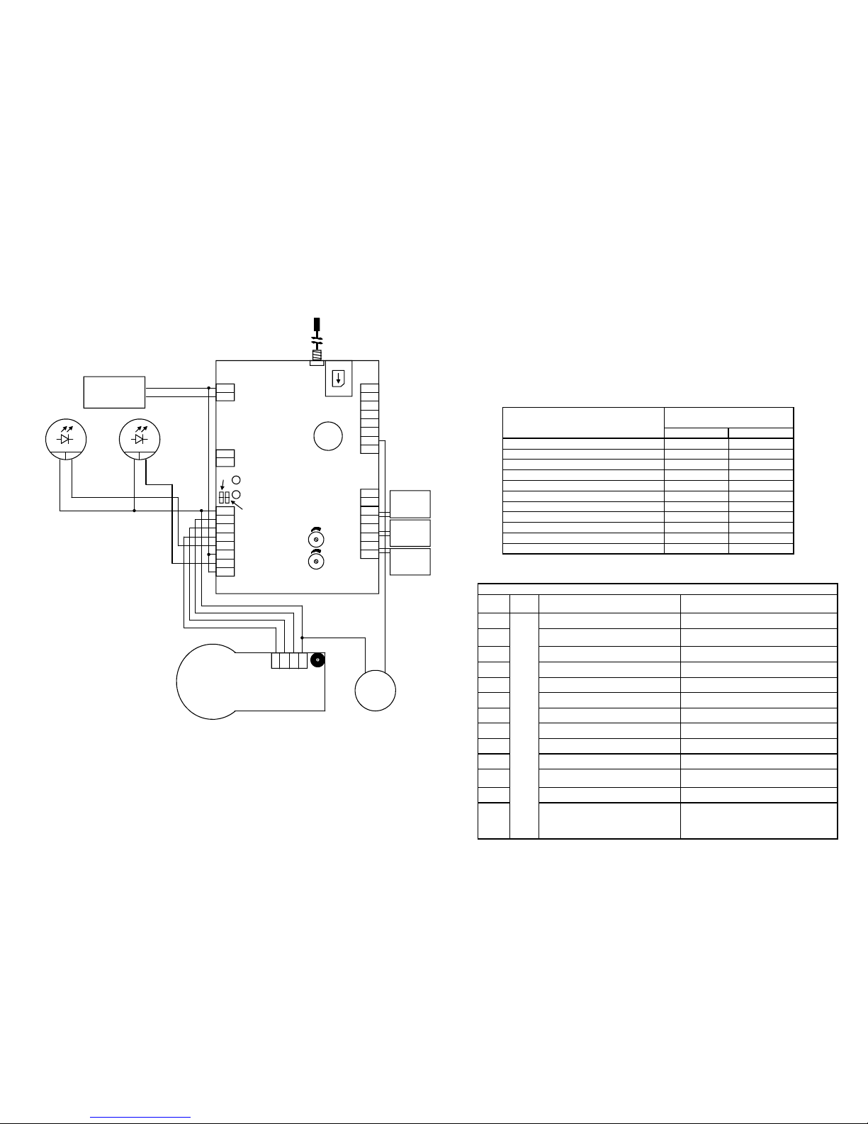
A.1) WIRING DIAGRAM
ANT1: Antenna
SMA: SMA Antenna connector
DLV1: GREEN Led “ON”
DLR2: RED Led “LINE”
TR1: Audio level from local phones to intercom
TR2: Audio level from intercom to local phones
JP5: Impedance regulation microphone
JP6: Impedance reegulation loudspeaker
SH1: GSM SIM Holder
PB1: 3V backup battery (CR2032) to keep RTC
CN1
1: + Power supply (12 Vdc)
2: - Power supply (Ground)
CN2
1 e 2: Telephone 1 “Pit”
3 e 4: Telephone 2 “Cabin Roof”
5 e 6: Telephone 3 “Engine Room”
7: Data line OUT
8: Data line IN
CN3
1 - 2: Contact “main alarm”
(cabin alarm)
3 - 4: Contact “alarm filter” or
Auxiliary alarm
5 - 6: Contact “Technologic 1” or
GONG
7 - 8: Contact “Technologic 2” or
GONG
CN4
1: Data OUT for battery LED
2: DatiaOUT for battery relay
CN5
1: Ground Intercom
2: Loudspeaker Intercom
3: Handsfree microphone
4: P/S microphone (12 Vdc)
5: Contact relay 1 NO
6: Contact relay 1 Common
7: Contact relay 2 NO
8: Contact relay 2 Common
8
7
6
5
4
3
2
1
CN3
CN2
1
2
3
4
5
6
7
8
CN5
1
2
CN4
1
2
CN1
8
7
6
5
4
3
2
1
SMA
SH1
PB1
DLR2
DLV1
TR2
TR1
JP6
ANT1
JP5
12Vdc
Loudspeaker
Microphone
Ground
Alarm
Button
Power supply
12Vdc / 500mA
+
-
INTERCOM
Alarm
Sent
lamp
+
-
Alarm
received
lamp
+
-
12Vdc 12Vdc
Cab Roof
Phone
Engine-
Room
Pit phone
For proper operation it is advisable to install
T.gsm at least 2 meters from electromagnetic
noise sources, switchgear, motors, power relays,
inverters and to use only new and dedicated ca-
bling.
21
C.3.11) CALL IDENTIFICATION CODES
When the operator requests the System ID (by pressing 4), T.gsm sends the 6 digit of the ID
(parameter “04”) and then the code corresponding to the type of call active (3 digit).
This coding is useful when managing T.gsm form an automated call center.
It is possible, on demand, to customize the codes identifying the type of the call. Please refer to
Teledif technical services.
Currently only two modes are available. The mode can be selected by setting parameter 11 (ref
section C.3.1, page 13).
Example: to select mode 2 set: 11 11 * 2 *.
C.3.12)
TELEPHONE DIRECTORY
TYPE OF CALL DTMF TONE CODE
MODE 1 MODE 2
Main Alarm: CABIN *01 D13
Allarme manutentori: PIT *02 D13
Allarme manutentori: CABIN ROOF *03 D13
Allarme manutentori: ENGINE ROOM *04 D13
Allarme BATTRY *07 643
TECHNOLOGICAL Alarm 1 *12 *12
TECHNOLOGICAL Alarm 2 *13 *13
LOW CREDIT Alarm *30 *30
END OF ALARM *20 523
REMOTE DIAGNOSTIC *05 583
INCOMING CALL *31 *31
TELEPHONE DIRECTORY
PAR. VAL FUNCTION YOUR NUMBER
80
Max
20
digit
End of Alarm
81 1st number Main and Maintainer
Alarm
82 2nd number
83 3rd number
84 4th number
85 5th number
86 Technological alarm 1
87 Technological alarm 2
88 Remote diagnostic
8 Battery Alarm
0 Low Credit or SIM expiration alarm
1 Auxiliary Alarm
By using this function it is possible
to set in a single operation the
same number for all the alarms
and reports (from rel. SW 2.1)
20
C.3.7.1) REPORT ALARM SENT” AND ALARM RECEIVED”
The signals for the cabin lamp relevant to Alarm Sent and Alarm Received are provided accor-
ding to the recommndations; T.gsm manages even better these signals by connecting them to
Relay 1 and 2 and programming them accordingly.
Report of Alarm sent”
When a procedure of Main or Maintainer Alarm is started the Relay 1, if programmed, can activa-
te the signal of “Alarm Sent”.
This signal can remain ON depending on the settings:
•
Until the “Alarm Received” signal is switched on (call suceeded)
•
Until the start of the End of Alarm procedure.
Report of Alarm received”
When an alarm call is acknowledged by pressing key 5, the Relay 2, if programmed, can start
the signalling of Alarm Received for a specified time.
C.3.8) TELEPHONE NUMBERS
T.gsm can manage up to 12 telephone numbers (parameters from 80 to 1) to forward specific
alarms or calls in Voice, Calling Line ID or SMS mode.
C.3.9) SMS MESSAGES
Whenever the system generates an SMS, for any reason, it includes together with the relevant
message also the information about the system status:
1. “Ver” system software version
2. “Rst” number of the times the system has reset between two consecutive telediagno-
stics. This number gives an indication about the fact that the system is installed for in-
stance too close to a source of electromagnetic noise (electric engine, inverter, switch, or
powered by non adegate cable, etc. )
3. “Vin” reports the supply voltage of T.gsm when the SMS has been generated.
4. “Residual Credit”: reports, if available, the value of the residual credit in the SIM.
When sendng SMS to the system:
1. It is not possible to record messages and to read system parameters
2. It is possible to program multiple parameters in the same SMS.
C.3.10) Calling Line ID Calls
In the case that the Calling Line ID mode is enabled the system call the telephone number set
for 10 seconds, then hang up; in this mode it communicate its number to the called party wi-
thout charge.
In the case that the called number is busy, T.gsm retry every 3 minutes until it finds the number
free and in any case until the completion of the number of loops specified.
5
Power supply
12Vdc / 500mA
+
-
8
7
6
5
4
3
2
1
CN3
CN2
1
2
3
4
5
6
7
8
CN5
1
2
CN4
1
2
CN1
8
7
6
5
4
3
2
1
CABIN KEY PANEL
With Alarm button and signalling LED
for Alarm Sent and Alarm Received and
handsfree phone
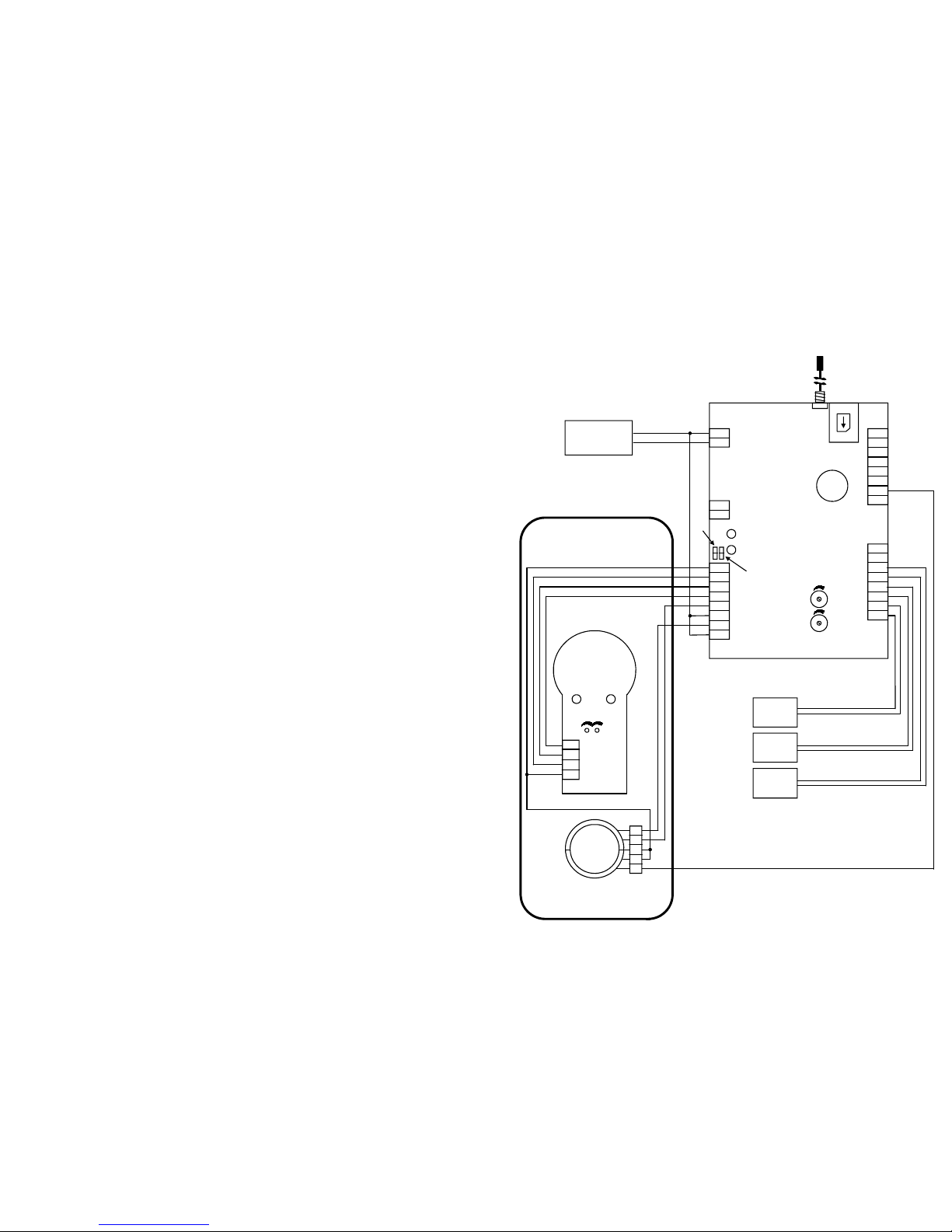
B.1) WIRING DIAGRAM WITH TELEDIF CABIN PANEL
Alarm Button
with
1 yellow led
and 1 green led
4321
12Vdc
Altoparlante
Microfono
Massa
For proper operation it is advisable to install
T.gsm at least 2 meters from electromagnetic
noise sources, switchgear, motors, power relays,
inverters and to use only new and dedicated ca-
bling.
HANDSFREE
TELEDIF ITALIA
SMA
SH1
PB1
DLR2
DLV1
TR2
TR1
JP6
JP5
ANT1
Cab Roof
Phone
EngineR.
Phone
Pit Phone
1
2
3
4
5
1 Green
2 Yellow
3 Black
4 RED NO
5 RED Common

6
O
PERATION
T.gsm has the following 4 status:
1. SELF TEST
2. OPERATION
3. PROGRAMMING
4. ERROR
C.1) SELF TEST
This status is shown by the Line RED Led slow flashing.
When switched on T.gsm automatically starts a self test procedure to check if there are the follo-
wing minimum operating conditions:
1. If at least one of the 5 telephone numbers for Cabin and Maintainer alarm is programmed
2. If the GSM module is properly working
3. If the SIM card is correctly inserted
4. If the SIM is not protected by a PIN
5. If there is a GSM signal
The self test procedure is performed whenever any of the following conditions happen:
•
System switch on
•
Local telephone hang-up after programming or cancelling the telephone numbers relevant to
Cabin and Maintainer alarm
•
Local telephone hang up after a system reset
After a self test the system moves to:
•
OPERATION: the RED led is OFF, see “C.2”.
•
ERROR: the RED led flashes quickly see “C.4”.
C.2) OPERATION
C.2.1) Events and priorities
T.gsm has the priorities in managing the events:
1. LOACAL TELEPHONES
2. CABIN ALARM (MAIN)
3. MAINTAINER ALARM
4. AUXILIARY ALARM (if enabled see page 14)
5. BATTERY ALARM
6. TECHNOLOGICAL ALARM 1 or Gong
7. TECHNOLOGICAL ALARM 2 or Gong
8. SIM LOW CREDIT ALARM
. SIM EXPIRATION ALARM
10. END ALARM
11. SELF TEST
12. INPUT CALL
Between two different GSM calls, in case the the system is managing an event and an higher
priority event shows up, the system start handling the new event; at the end it resume mana-
ging the first event.
19
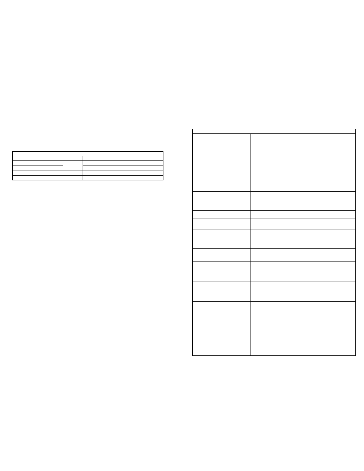
C.3.7) RELAY
PARAMETER VALUE De-
fault Yr Value FUNCTION NOTE
70 0 to 6 Relay 1
0 = Relay 1 is active for the duration
of the DTMF
1 to 4:
Realy is active from 1 to 4 seconds.
i.e.: setting the value “3”, when acti-
vated the relay remains closed for 3
seconds
5 = The relay 1 works in latch mode
(step-step): each push of key 1 chan-
ge the state (close or open)
6 to 9 used to confirm: “Alarm sent”
6 = Active until the start of the “End
of Alarm” procedure
7 = Active until the call has been
accepted (key 5)
8 = Active intermittently until the
start of the “End of Alarm” procedure
9 = Active intermittently until the call
has been accepted (key 5)
When reading this parameter the
system returns the value of the para-
meter and the actual state of the relay
(ON or OFF)
71 0 to 6 6 Relay 2
0 = Relay 2 is activated for the dura-
tion of the DTMF
1 to 4:
Realy is active from 1 to 4 seconds.
i.e.: setting the value “3”, when acti-
vated the relay remains closed for 3
seconds
5 = The relay 1 works in latch mode
(step-step): each push of key 1 chan-
ge the state (close or open)
6 = used to report “Alarm received”:
it is active fix for the time set with
parameter 72 starting from the ackno-
wledgement of the call (key 5)
When reading this parameter the
system returns the value of the para-
meter and the actual state of the relay
(ON or OFF)
72 001 to
010 Activation time
of the Relay 2
SECONDS
Default for parameter 71 = 6
RELAY

18
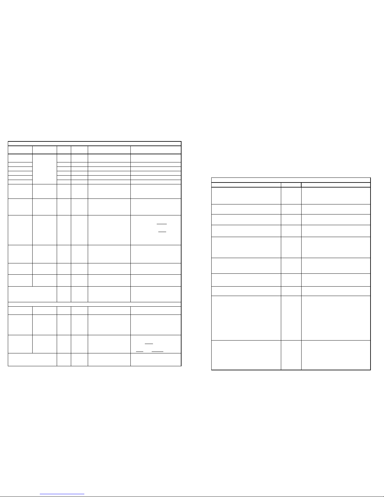
C.3.6) TECHNOLOGIC ALARM 1 (T1) a d TECHNOLOGIC ALARM 2 (T2) or
Go g sou d 1 a d 2
TECNOLOGIC ALARM 1 a d 2 or GONG
PARAMETER
VALUE Default Yr
Values FUNCTION
T1 T2
86 87 Max 20
digit - -
Tel numbers for techno-
logical alarms 1 (T1)
and 2 (T2)
N. T1:
N. T2:
60 65 0 to 2 Number of alarm loops 0 = ENDLESS
61 66 01 to 10
Time between two su-
ceeded calls when the
alarm is still ON, or
between a call sucee-
ded and the next one or
between an alarm not
acknowledged (max
loops) and the start of
the next loop
HOURS
62 67 0001
to 0060
Minimum time for the
contact to stay open or
close to validate the
alarm
SECONDS
63 68 1 to 4 1 Mode of operation of
the alarm contact
1 = N/O
2 = N/C
The system stops the
procedure in the ab-
sence of the alarm
condition (reopening
or closing of the
contact)
3 = N/O
4 = N/C
The system does not
stop the procedure in
absence of the alarm
condition (reopening
or closing of the
contact)
64 6 0 to 3 0 Call mode: voice, CLID
or SMS
0 = Voice call
1 = Calling Line ID
call
2 = SMS message
3 = Bell/gong sound
in the cabin
Fix Value 3 - - Time between two fai-
led calls
MINUTES
The calling Line ID call
is considered sucee-
ded when the dialled
number is free.
The SMS sent is al-
ways considered suc-
cessful.
NOTE
7
C.2.1.1) Local telephones
T.gsm supports 3 local phones:
Phone 1 = Pit
Phone 2 = Cabin Roof
Phone 3 = Engine Room
From the local telephone it is possible to:
•
Start the end of alarm procedure, if enabled
•
Command the relays, if properly programemd
•
Start a the specific alarm: pit, cabin roof, engine room
•
Request System ID
•
Talk with the cabin intercom
•
Start the remote diagnostic, if the system is idle
•
Cancel and operation in progress
•
Program the T.gsm
•
Check system settings
•
Record and play the voice messages
Operations from the local phones have a timeout for entering the DTMF codes; if no key is pres-
sed within 60 seconds the command are disabled until the key star is pressed. The timeout is
announced with a voice message.
C.2.1.2) Cabin alarm (main)
An alarm call is forwarded by pushing, for a programmed time, the alarm button in the cabin;
the system, if the parameter hes been set, send a pre-alarm message, then start the alarm pro-
cedure and play a reassurance message in the cabin.
The alarm call is considered successful if:
•
The called number answers and acknowledge the call by pressing “5”
•
The alarm is stopped by the maintainer phone, in the referred cases
The called party receives an identification message (location), if recorded; by pressing the 5 key
he is connected to the cabin and can talk to the cabin intercom. The called party can also activa-
te all the functions provided by the system programming using the telephone keyboard.
T.gsm can store up to 5 phone numbers for cabin and maintainer alarm; the system dial these
numbers in a loop until it receives a valid answer or until the programmed number of loops.
At the start of each new loop the system play a reassuring message to the cabin.
The reports of Alarm Sent and Alarm Received, if not differently managed, can be automatically
activated by the relays, when programmed.
C.2.1.3) Maintainer alarm (from the telephones: pit, cabin roof, engine room)
A maintainer alarm call (trapping in the pit, cabin roof or engine room) can be generated by any
of the local phones, just by lifting the handset and pressing 3. The system call the number sto-
red for the main alarm, at the answer play the identification and location message and, if ena-
bled with parameter 27, the relevant alarm message (from sw version 2.1).
C.2.1.4) Auxiliary alarm or filter main alarm (cabin)
The “call filter” feature allows to disable, when active, the transmission of the main alarm.
The filter is generated by a logic contact programmable as NO or NC.
When properly programmed, this contact can also be used as an auxiliary alarm contact (ref.
Page 14, parameter 22).

8
C.2.1.5) Battery alarm
T.gsm generate a battery alarm whenever the battery voltage drops below the programmed
value for a programmed time.
The system is also equipped with a data input (CN2-8 and ground) to manage a signal coming
from the power supply with intelligent battery charger T.ali.
The battery alarm is reported in one of the following ways:
•
A call to the number programmed, followed by the message identifying the system followed
by the message battery alarm
•
A call to a programmed number in CLID mode
•
Sending an SMS to the number programmed
C.2.1.6) Technological alarm 1 and 2 or Bell contacts
The system is equipped with 2 inputs, individually programmed and configured for technological
alarms or for the sound of a bell through the cabin intercom loudspeaker.
Each contact can be programmed N/O or N/C; the trigger time (the time that the contact must
stay Open or Closed to start the procedure) can also be programmed.
The technological alarm is reported in the following ways:
•
A call to the number programmed, followed by the message identifying the system followed
by the message of technological alarm 1 or 2
•
A call to a programmed number in CLID mode
•
Sending an SMS to the number programmed
C.2.1.7) SIM Credit Alarm and SIM Expiration alarm
SIM CREDIT: T.gsm performs a daily procedure to enquiry the credit (according to the operator);
when the credit is below the value set, T.gsm sends the relevant alarm, if programmed (page 17
parameter 56)
The credit alarm is reported in the following ways:
•
A call to a programmed number in CLID mode
•
Sending an SMS to the number programmed
SIM EXPIRATION: if parameter 57 is programmed the system send an alarm message with the
modalities set in parameter 56.
C.2.1.8) End of Alarm
T.gsm, after a cabin or a maintainer alarm, can manage the end of alarm call in different ways
that can be enabled from local or remote:
a. From remote:
•
After an alarm received, by pressing “0” before hanging up when in communication
with the cabin intercom or one of the maintainers phones
•
Following an alarm call, by recalling the T.gsm number that has generated the alarm
and pressing “*” <password> “0”.
b. From a local phone:
•
Picking up the handset then pressing “*” <password> “0”.
The end of alarm procedure performs the following functions:
•
Switch off the end of alarm signal, if managed by a T.gsm relay
•
Start a call to the programmed number and at the answer plays the relevant message.
If both the relays and the telephone number are not programmed, T.gsm acknowledges the end
of alarm command with the message “Wrong code”.
17
BATTERY ALARM
PARAMETER VALUE Default Yr
Value FUNCTION NOTE
8 Max 20
digit - - Tel No. for Battery
Alarm N.:
50 0 to 0 Number of loops 0 = ENDLESS
51 100 to
150 110 Threshold
Tenths of Volt (+/- 0,1V)
Example: 105 = 10,5
Vdc
52 00 to 01 Time below the thre-
shold MINUTES
53 00 to 01
Time between two
battery alarm calls
suceeded (confimed
by “5”) with battery
alarm ON or with the
number of loops com-
pleted without ackno-
wledgement and with
the alarm still ON
Espresso in ORE
Example: setting the
parameter to “02”, if the
alarm signalling has
been acknowledged (by
key 5) the system
send an alarm call every
2 hours until the pro-
blem is solved.
54 0 to 3 0 Call mode: voice,
CLID or SMS
0 = Voice call
1 = Calling Line ID CALL
2 = SMS message
3 = Send an SMS for the
Alarm, and, if connected
with T.ali(*), send an
SMS also in case of
power failure and power
restore.
Parameters 2 or 3, if
active, disable parame-
ter 53
Fix Fix 3 - Time between two
failed calls MINUTES
LOW CREDIT AND SIM EXPIRATION ALARM
0 Max 20
digit - -
Tel number to check
the credit and the
expiration of the SIM
N.:
55 01 to 01 Credit limit
In EURO
If the credit is below to
the limit set the system
start the credit Alarm
procedure.
The credit is controlled
every day. When reading
this parameter the
system play the residual
credit figure in Euro and
Cents (from rel. SW
2.1). The decimal is read
by a beep
56 0 to 2 0 Not enough credit
Alarm
0 = Disabled
1 = Calling Line ID
2 = SMS
57 MMGG 0000 SIM expiration SMS
message
MM = Month
DD = Day
0000 = Disabled
(*) T.ali is the intelligent power supply with battery charger

16
C.3.4) REMOTE DIAGNOSTIC
The remote diagnostic is the procedure used by the system to communicate that it is well perfor-
ming and in operation.
NOTE: system data and time must be properly configured (parameter “10”).
C.3.5) - BATTERY ALARM
- LOW CREDIT
- SIM EXPIRATION
T.gsm check continuosly the voltage of the power supply on connector CN1 and start an alarm
procedure if the voltage is below the value set with paremeter “51” for the time duration set in
parameter “52”.
To verify the low credit condition the system check the daily SMS coming from the operator in
response to the SMS enquiry. This procedure is factory preset for different countries/operators.
Please contact Teledif to check that you country/operator variant is available.
Teledif Italia does not assume any responsibility for errors or for expenses charged by any
operator for any reason.
PARAMETER VALUE Default Yr
Values FUNCTION NOTE
88 Max 20
digits - - Remote diagnostic tel.
number N.
40 0 to 2 Number of loops 0 = ENDLESS
41 01 to 03 Time between two
remote diagnostic calls DAYS
42 00 to 23 10 Hour of the call HR=
43 00 to 5 00 Minute of the call Min=
44 0 to 2 0 Mode to operate the
remote diagnostic
0 = Call with voice messa-
ge
1 = Calling Line ID Call
The system communicate
its CLID to the called user
2 = SMS call
The system send the dia-
gnostic via a preset SMS,
including System ID and
message explanation
Fix 3 - Time between two
failed calles MINUTES
REMOTE DIAGNOSTIC
9
C.2.1.9) Self test
The system has two different self test modes:
•
On demand
•
On schedule: at time programmable intervals (day/hour/minute)
A self test call can be performed in the following ways:
•
Dialling a programmed number and sending ID messages
•
Dialling a programmed number in Calling ID (CLI) mode L’invio di un SMS al numero pro-
grammato
•
Sending an SMS to the number specified
An on demand self test can be started from a local phone or from a remote phone.
a. Request from a local phone:
1. Lift the handset
2. Dial Star and the password
3. Dial 6
4. Hang up
The system starts a self test to the phone number programmed and plays a voice message.
b. Request from a remote phone:
1. Dial the telehone number of the system
2. At the answer (ID message), dial star, the password and the key 6
3. Hang up
The system starts a self test to the phone number programmed and plays a voice message.
C.2.1.10) Incoming call
T.gsm answers an incoming call after the specified number of rings, by playing the ID message.
To access to the system dial the following commands:
1. Star (*)
2. The system answers with the message “enter password” or “insert code”
3. Dial the password, if programmed, if not dial directly the control code for the command or
procedure you want to activate
4. The system answers with the message "password correct" or "password incorrect", "correct
code" or "wrong code" or with the corresponding function message
5. Dial 5 to open the voice channel with the hands-free of the cabin (the cabin, for privacy rea-
sons is warned by a “beep”, at regular intervals)
6. To close the connection dial " " or hang up
If you do not enter the key * (star) within the time set with parameter 05, the system warns
with a sound signal indicating the timeout and then it releases after 10 seconds.
In the case of the occurrence of an event with higher priority the incoming call is closed and the
system will initiate the procedure to manage the new event.
NOTE: When generating DTMF tones from remote it is sometime possible that the DTMF tones
are not always properly recognized, due to radio GSM repeaters and to the noise in case of weak
signal. In this case the following precautions must be used in sending DTMF tones:
1. Only send DTMF when system messages are ended
2. Wait at least one second between each digit

10
C.2.1.11) Answer to an alarm call generated by T.gsm
When the operator of the call center answers the call, he receives the System ID message
(recordable message, parameter 30) followed by the message indicating the alarm originator
(cabin, pit, cabin roof or engine room) and by the instructions on how to accept the alarm and
get in communication with the caller (“dial 5 to connect”).
The messages are repeated until the operator dial 5 or disconnect dialling , or the answer time-
out expires (parameter 6).
Dialling 5, if programmed:
•
Activate realy 2 (alarm received) for the programmed duration(parameter “72”),
•
Open the voice communication between the cabin intercom and the called number
•
Start the “conversation timeout” for the time specified (parameter “05”).
When approaching the end of timeout (10 seconds from the end) beeping tones are pla-
yed. Dialling any number regenerates the time out.
While connected it is possible to access to "remote controls" (Section C.2.2) using the relevant
codes; if wrong codes are used, the system answer with the message “wrong code”.
T.gsm returns to idle state after receiving , when the line is released or at the expiration of the
communication timeout.
C.2.1.12) Cancelation of the procedure in progress
T.gsm gives the possibility to cancel an alarm procedure in progress.
To cancel the procedure:
1. Lift the handset of a local phone
2. Dial star
3. If the system has not yet performed the call, it will answer with a message relevant to the
active procedure
4. Press
5. T.gsm will play the message “good code”
6. The proceduer is then canceled and it is possible to hang up
NOTE: if the procedure is performed while a call is already in progress the system will not allow
the cancelation and will open the voice communication between the GSM line and the local pho-
nes allowing to listen to line events. For security reasons it is not possible to cancel the procedu-
re if the system is performing the first calling cycle.
15
To delete a stored telephone number or a previosusly set value start the programming mode for
the parameter and enter an empty “value”. Example 11 82 **.
If it is required to send and SMS instead or in addition to the phone call when a Cabin or Maintai-
ner Alarm starts, when programming include as a first character of the value field pound (#).
The SMS is managed as a call suceeded and is therefore sent only once, also in case of more
than one loop for a successful phone call. If it is requested that an SMS is always sent, it is ne-
cessary to program the relevant number in the first position, since the acknowledgement of a
phone call (key 5) stop the calling loop and therefore any SMS call.
Example: with the following settings 11 81 * # 3355 54488 * and 11 82 * 800 800 800* the
system starts the alarm procedure by sending the sms to the first number (3355 54488) then
start the calling loops to the phone number (800800800).
C.3.3) MESSAGGES
The system provides 2 types of messages
1. System messages: factory stored messages that cannot be cahnged by the user.
2. User recordable messages: 6 messages that can be associated to specific functions.
In order to record good quality messages, the length of each message must be determined and
programmed before recording it.
To record a message from a local or a remote phone:
1. Push * (star)
2. Dial the password (if requested)
3. Push # (pound) to enter programming mode
4. Dial the code of the message to record as follows
11 33 * 08 * where:
11 to start writing mode
33 code of the message to record (i.e. “technological 2”)
* star
08 = duration of the message to be recorded
* star
6. The system will answer: “ Please start recording after the beep”
7. Speak clearly into the microphone of the handset
8. Once the programmed time is expired the system will answer: “Message recorded”
. To listen to the message dial 12 and the message code. In this example 12 33 to listen to
the message associated to the technological 2 alarm.
10. If the recording is not satisfactory repeat the procedure from point 4.
NOTE: In case the recording is noisy or bad quality, check the quality of the power supply and of
the telephone used. A system reset does not cancel the messages recorded.
PARAMETER VALUE DEFAULT MESSAGE ASSOCIATED NOTE
30 02 to 20 - System LOCATION
In SECONDS
Lenght of the message
to record
The message played is
relevant to the parame-
ter selected
31 02 to 20 - Cabin REASSURANCE
32 02 to 15 - Technologycal 1
33 02 to 15 - Technologycal 2
34 02 to 15 - Auxiliary Alarm
35 02 to 15 - Cabin Alarm
RECORDABLE MESSAGES
14
C.3.2) - MAIN AND MAINTAINER ALARM (PIT, ROOF, ENGINE ROOM)
- AUXILIARY ALARM OR FILTER MAIN ALARM
- END OF ALARM
MAIN AND AUXILIARY ALARM
PARAMETER VALUE De-
fault
Yr
Values FUNCTION NOTE
81
Max 20
digit
- - 1° Phone number main
and maintainer alarm Your n:
82 - - 2° Phone n. Your n:
83 - - 3° Phone n. Your n:
84 - - 4° Phone n. Your n:
85 - - 5° Phone n. Your n:
1 - - Auxiliary alarm ph. n. Your n:
20 0 to 2 N. of loops for main/
auxiliary alarm 0 = ENDLESS
21 0 or
2 to 2
Minimum press time
for the main/aux alarm
button
In SECONDS
0 = immediate start wi-
thout pre alarm message
22 0 to 3 0 Aux alarm contact or
Filter Cabin alarm
0 = Filetr disabled
1 = N/O: if closed, cabin
alarm is not generated
2 = N/C: if open, cabin
alarm is not generated
3 = Contact used as auxi-
liary alarm
23 1 or 2 1
Method of operation of
the contacts main and
aux alarm
1=ON N/O(Normally open)
2=ON N/C(Normally closed)
24 0 or 1 1 Delivering of the mes-
sage pre-alarm”
0 = OFF
1 = ON
Fix 5 -
Time between two
failed alarm calls
(main, aux and main-
tainer alarm)
In SECONDs
80 Max 20
digit - - Number end of alarm Your n:
25 0 to 2
Number of retries for
the tel. number for
end of alarm if unsuc-
cessful
0 = ENDLESS
26 1 or 2 1 How to manage the
end of alarm
1 = Start end of alarm only
from a local phone
2 = Start end of alarm from
a local or a remote phone
Fix 3 -
Time between two
unsucessfull end of
alarm calls
In MINUTES
END OF ALARM
27 0 or 1 1
Delivering of the mes-
sage Maintainer alarm
(from SW 2.1)
0 = OFF
1 = ON
11
C.2.2) System access and control codes
The access to the system is possible in two ways:
a. From a local phone:
1. Lift the handset of a local phone
2. Press the star key
b. From a remote phone:
1. Dial T.gsm telephone number
2. At the answer (ID message), press the star key
In both cases it is necessary to dial the password (only if active, i.e. different from “0000”).
Once accessed to the system it is possible to use the “TELECONTROL” o “PROGRAMMING” codes
REMOTE CONTROL CODES
FUNCTION CODE ACTIONS T.gsm
End of Alarm 0
Start, as soon as possible, the “End of
Alarm” procedure (only further to a
MANTEINER or CABIN ALARM)
Activate Relay 1 1 Control relay 1 according to parameter
“70”
Activate Relay 2 2 Control relay 2 according to parameter
“71”
Maintainer Alarm 3
Send Alarm “pit” o “cabin roof” or
“engine room” according to the phone
originating the alarm
ID Request (System ID code) 4
Send through DTMF tone the identifica-
tion code programmed (parameter
“04”) and the code of the typology of
the call (parameter “11” , sect.
“C.3. ”)
a. Enable conversation
b. Acknowledge the call
c. Reload the “Communication Time-
out”
5
a. Open the communication with the
cabin
b. Call suceeded
c. Extend the timeout
Self Test request 6
Start a procedure for a self test diagno-
stic with a call to a programmed num-
ber
Listen to the location message 7 Play the location message
a. Terminate the conversation
b. Terminate a call
c. Cancelation of a procedure
a. Close the audio from the local pho-
nes to the intercom
b. Hang up the call in case the call is:
⇒
Outgoing and accepted by
key 5
⇒
In co mi n g w i th c o r r ec t
password
c. In case an alarm procedure is on-
going and the start key is pressed,
the procedure is canceled
Switch audio between GSM and inter-
com or GSM and phone *
a. From remote phone: it is possible
to switch the audio from the inter-
com to the local phones
b. From a local phone: if a call is
active it is possible to talk to the
remote phone or to the cabin
12
C.3) PROGRAMMING
Programming allows to Read and Write system parameters and use the following syntax:
To Write:
WRITE CODE (11) + PARAMETER + STAR (*) + VALUE + STAR (*)
To Read:
READ CODE (12) + PARAMETER
To start programming from a phone:
1. From a local or remotye phone access to the system
•
Form a local phone lift the handset and dial * (star);
•
From a remote phone, dial the telephone number of the T.gsm system; after
listening to the Location message dial * (star);
2. Wait the message requesting the password
3. Dial the password
•
Wait the message password correct
4. Dial # (pound)
•
Wait for the message confirming the access to the programming mode
5. Dial the programming codes with the relevant parameters, following the correct
syntax
•
At each correct programming step the system plays the message: “correct
code”
•
At each wrong or not possible or not recognized programming step the system
plays the message: “wrong code”
6. To exit programming hang up or dial # (pund)
•
The system plays an acknowledgement message
To programm or change a setting with an SMS:
1. Prepare a message containing the programming codes as it is done from a phone
(see “Example 1”)
2. Send the message to the T.gsm telephone number
3. The system acknowledge by replying to the number that sent the programming
string with a SMS containing one of the following messages:
•
“Wrong Password”: the password is not correct
•
“Successful programming”: everything is correct
•
“Wrong programming”: the password is correct but there is one or more pro-
gramming errors
Example 1:
* 1234 # 11 02 * 5 *
Wgere: “*” to access to the system, “1234” is the password, “#” allows to access to the
programming mode, “11” WRITE code, “02” parameter, “*” start of parameter field “5”
new value of the parameter, “*” end of parameter field
When in programming mode the system has a timeout of 60 seconds; at the expiration of the
timeout the system plays the message :”Timeout expired” and exit. To reenter it is necessary to
start again the programming procedure.
PROGRAMMING CODES
FUNCTIONS CODE ACTIONS T.gsm
Enter in program mode # Request PROGRAMMING codes
Exit program mode Request TELECONTROL codes
WRITE Code 11 WRITE a value to a parameter
READ Code 12 READ a value from a parameter
13
C.3.1) SYSTEM SETTINGS
PARAME-
TER VALUE De-
fault
Yr
Va-
lues
FUNCTION NOTE
00 00 - - Reset program-
ming
Reset all parameters to
the default value
(do not erase messa-
ges and do not change
system data/time)
Write only
01 0000 to 1234 Password 0000 = password disa-
bled
02 1 to 2 Rings No of rings to answer
to an incoming call
03 0 to 6 - - GSM Signal
0 = GSM signal weak
or absent
6 = GSM signal max
Read only
04 000000 to
0000-
00 System ID -
05 01 to 02 C o m m un i c a t i on
Timeout
In MINUTES
06 010 to 060 Waiting confirm
In SECONDS
Waiting time between
the start of the selec-
tion and the acknowle-
dgement (dial key 5)
07 - - - Software Release
Example: 10 means
release 1.0
Read only.
08 01 to 13 07 Audio level lau-
dspeaker GSM
Audio level from the
GSM to the intercom
0 1 to 3 2 Audio level micro-
phone GSM
Audio level from the
intercom to the GSM
10 YYMMDDhhmm - - System DATA and
HOUR setting
YY = Year
MM = Mese
DD = Day
hh = Hour
mm = Minute
11 1 or 2 1
How to manage
call identification
codes
Dialling 4 after recei-
ving the system ID (6
digit)the system an-
swer with the active
alarm code (3 digit)
See section “C.3.11”
12 - - - Current supply
voltage
In TENTH of VOLT (+/-
0,1V)
I.E.: 125 = 12,5 Vdc
Read only
SYSTEM PARAMETERS
Other manuals for T-gsm
1
Table of contents
Other Teledif Emergency Phone manuals

Popular Emergency Phone manuals by other brands


Future Call LLC.
Future Call LLC. Emergency 911 user manual

LogicMark
LogicMark GUARDIAN ALERT 911 User's quick start guide

ANEP
ANEP BOX-C manual
LogicMark
LogicMark CaretakeSentry 40914 Quick install guide

PPP Taking Care
PPP Taking Care Your Personal Alarm Setup & user guide

AVIRE
AVIRE MEMCO Memcom installation guide

CVI
CVI ViAC-RTK Installation and operation manual

SPOT
SPOT Satellite GPS Messenger user guide

Safeline
Safeline MX2 installation manual

Assistive Technology Services
Assistive Technology Services Help Dialer 700 troubleshooting guide

Viking
Viking E-1600A series Technical practice

Viking
Viking E-1600 Application note