Teledyne Lecroy T3AFG30 User manual

T3AFG30-60
Function / Arbitrary Waveform Generators
User Manual

This page is intentially left blank

Contents
General Safety Summary ................................................................................. I
Introduction to the T3AFG30-60 ...................................................................... II
1 Quick Start ................................................................................................1
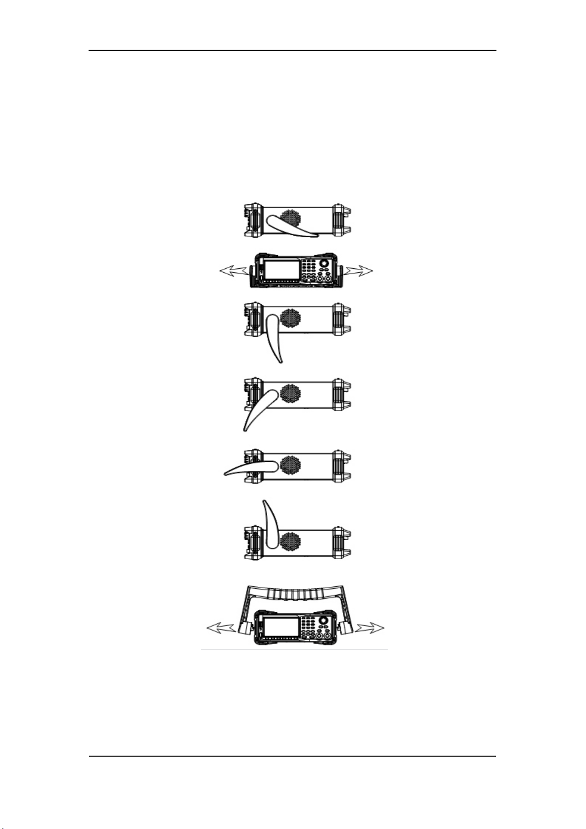
1.1 Handle Adjustment .............................................................................. 2
1.2 The Front/Rear Panel .......................................................................... 3
1.3 To Select a Waveform .......................................................................... 8
1.4 To Set Modulation/Sweep/Burst ..........................................................12
1.5 To Turn On/O Output .........................................................................14
1.6 The Numeric Keyboard........................................................................15
1.7 The Common Function Keys...............................................................16
2 Front Panel Operations ............................................................................... 17
2.1 To Set Sine Waveform ........................................................................ 18
2.2 To Set Square Waveform ....................................................................23
2.3 To Set Ramp Waveform ......................................................................26
2.4 To Set Pulse Waveform .......................................................................28
2.5 To Set Noise Waveform.......................................................................32
2.6 To Set DC Waveform...........................................................................35
2.7 To Set Arbitrary Waveform...................................................................36
2.8 To Set Harmonic Function ...................................................................45
2.9 To Set Modulation Function.................................................................48
2.9.1 AM...............................................................................................49
2.9.2 DSB-AM ......................................................................................52
2.9.3 FM...............................................................................................53
2.9.4 PM...............................................................................................55
2.9.5 FSK .............................................................................................57
2.9.6 ASK .............................................................................................59
2.9.7 PSK.............................................................................................60
2.9.8 PWM ...........................................................................................61
2.10 To Set Sweep Function................................................................ 64
2.11 To Set Burst Function .................................................................. 69
2.12 To Store and Recall......................................................................75
2.12.1 Storage System ........................................................................76
2.12.2 File Type ...................................................................................77
2.12.3 File Operation ...........................................................................79
2.13 To Set Utility Function ..................................................................82

2.13.1 System Settings ....................................................................... 84
2.13.2 Test/Cal .................................................................................... 92
2.13.3 Frequency Counter .................................................................. 96
2.13.4 Output ...................................................................................... 99
2.13.5 CH Copy/Coupling ................................................................. 102
2.13.6 Remote Interface ................................................................... 107
2.13.7 Sync Output ........................................................................... 112
2.13.8 Clock Source.......................................................................... 114
2.13.9 Mode ...................................................................................... 115
2.13.10 Overvoltage Protection ........................................................ 117
3 Examples...................................................................................................118
3.1 Example 1: Generate a Sine Waveform ........................................... 119
3.2 Example 2: Generate a Square Waveform....................................... 120
3.3 Example 3: Generate a Ramp Waveform......................................... 122
3.4 Example 4: Generate a Pulse Waveform ......................................... 124
3.5 Example 5: Generate a Noise .......................................................... 126
3.6 Example 6: Generate a DC Waveform ............................................. 127
3.7 Example 7: Generate a Linear Sweep Waveform ............................ 128
3.8 Example 8: Generate a Burst Waveform.......................................... 130
3.9 Example 9: Generate an AM Modulation Waveform ........................ 132
3.10 Example 10: Generate a FM Modulation Waveform ...................... 134
3.11 Example 11: Generate a PM Modulation Waveform....................... 136
3.12 Example 12: Generate a FSK Modulation Waveform..................... 138
3.13 Example 13: Generate an ASK Modulation Waveform................... 140
3.14 Example 14: Generate a PSK Modulation Waveform .................... 142
3.15 Example 15: Generate a PWM Modulation Waveform................... 144
3.16 Example 16: Generate a DSB-AM Modulation Waveform.............. 146
4 Troubleshooting .........................................................................................148
4.1 General Inspecting............................................................................148
4.2 Troubleshooting ................................................................................149
5 Service and Support..................................................................................150
5.1 Maintenance summary......................................................................150
5.2 Contact Teledyne LeCroy..................................................................151
6 Appendix....................................................................................................152
Appendix A: Accessories ........................................................................ 152
Appendix B: Daily Maintenance and Cleaning ....................................... 153

User Manual I EAR99 technology subject to restrictions on copyrights page
© 2021 Teledyne LeCroy, Inc. All rights reserved.
Users are permitted to duplicate and distribute Teledyne LeCroy, Inc.
documentation for internal educational purposes only. Resale or unauthorized
duplication of Teledyne LeCroy publications is strictly prohibited.
Information contained herein is classied as EAR99 under the U.S. Export
Administration Regulations. Export, reexport or diversion contrary to U.S. law
is prohibited.
Teledyne Test Tools is a trademark of Teledyne LeCroy, Inc., Inc. Other product
or brand names are trademarks or requested trademarks of their respective
holders. Information in this publication supersedes all earlier versions.
Specications are subject to change without notice.
General Safety Summary
Carefully read the following safety precautions to avoid any personal injuries
or damage to the instrument and any product connected to it. To avoid
potential hazards, please use the instrument as specied.
Only qualied technical personnel should service this instrument.
Avoid re or open ame.
Use properly rated power line connections.
Use only the specied power line which has been approved by your local
regulatory agency.
Ground the Instrument.
The instrument is grounded through the protective ground conductor of the
power line. To avoid electric shock, the ground conductor must be connected
to the earth ground. Make sure the instrument is grounded correctly before
connecting its input or output terminals.
Connect the signal wire correctly.
The potential of the signal wire ground is equal to the earth, therefore do not
connect the signal wire to a high voltage. Do not touch the exposed contacts or
components.

EAR99 technology subject to restrictions on copyrights page User Manual II
Safety Terms and Symbols
Terms used on the instrument
These terms may appear on the instrument:
DANGER:
Direct injury or hazard may occur.
WARNING:
Potential injury or hazard may occur.
CAUTION:
Potential damage to instrument/property may occur.
Symbols used on the instrument
These symbols may appear on the instrument:
Frame or
Chassis
Terminal
CAUTION
Risk of
injury or
damage.
Refer to
manual.
WARNING
Risk of
electric
shock or
burn
Earth
Ground
Terminal
Alternating
Current
Protective
Conductor
Terminal
ON/
Standby
Power
Observe all terminal ratings.
To avoid re or electric shock, please observe all ratings and sign instructions
on the instrument. Before connecting the instrument, please read the manual
carefully to gain more information about the ratings.
Do not operate with suspected failures.
If you suspect that the product is damaged, please let only qualied service
personnel check it.
Avoid circuit or wire exposure.
Do not touch exposed contacts or components when the power is on.
Do not operate in wet/damp conditions.
Do not operate in an explosive atmosphere. Keep the surface of the
instrument clean and dry.

User Manual III EAR99 technology subject to restrictions on copyrights page
Introduction to the T3AFG30-60
This manual covers the following two models of the T3AFG Series Function/
Arbitrary Waveform Generators: T3AFG30 and T3AFG60.
The T3AFG30-60 are dual-channel function/arbitrary waveform generators with
specications of up to 60MHz maximum bandwidth, 150MSa/s sampling rate
and 14-bit vertical resolution. The proprietary EasyPulse technology helps to
solve the weaknesses inherent in traditional DDS generators when generating
pulse waveforms, and the enhanced square wave generator is capable of
generating square waveforms with up to 60MHz frequency and low jitter. With
these advantages, the T3AFG30-60 can provide users with a variety of high
delity and low jitter signals and can meet the growing requirements of complex
applications.
Key Features
• Dual-channel with a bandwidth up to 60MHz and amplitude up to 20Vpp
• 150MSa/s sampling rate, 14-bit vertical resolution, and 16kpts waveform
length
• Innovative Easy Pulse technology, capable of generating lower jitter Pulse
waveforms, brings a wide range and extremely high precision in pulse width
and rise/fall times adjustment
• Enhanced circuit for Square waves, which can generate a Square wave with
frequencies up to 60MHz and jitter less than 300ps+0.05ppm of period
• A variety of analog and digital modulation types: AM, DSB-AM, FM, PM,
FSK, ASK, PSK and PWM
• Sweep and Burst functions
• Harmonic waveform generation function
• Waveform combine function

EAR99 technology subject to restrictions on copyrights page User Manual IV
• High precision Frequency Counter
• 196 built-in arbitrary waveforms
• Standard interfaces: USB Host, USB Device(USBTMC),
LAN(VXI-11)
• 4.3 inch display

User Manual 1 EAR99 technology subject to restrictions on copyrights page
1 Quick Start
This chapter covers the following topics:
�Handle Adjustment
�The Front/Rear Panel
�To Select a Waveform
�To Set Modulation/Sweep/Burst
�To Turn On/O Output
�To Use Numeric Input
�To Use Common Function Keys

EAR99 technology subject to restrictions on copyrights page User Manual 2
1.1 Handle Adjustment
To adjust the handle position of the
T3AFG30-60
, please grip the handle by the
sides and pull it outward. Then, make the handle rotate to the desired position.
Figure 1-1 Viewing Position and Carrying Position

This chapter provides a brief introduction and description for the front/rear
panel operation and functions.
Front Panel
The T3AFG30-60 has a clear and simple front panel, it includes a 4.3 inch
screen, menu softkeys, numeric keyboard, knob, function keys, arrow keys,
and channel control area.
Figure 1-2 Front Panel
User Manual 3 EAR99 technology subject to restrictions on copyrights page
1.2 The Front/Rear Panel
USB
Host
Numeric Keyboard
Knob
Power
Button
User Interface
Menu
Softkeys
Function
Keys
Channel
Control
Arrow
Keys

EAR99 technology subject to restrictions on copyrights page User Manual 4
Rear Panel
The rear panel provides multiple interfaces, including Counter, 10MHz In/Out,
Aux In/Out, LAN, USB Device, Earth Terminal and AC Power Supply Input.
Figure 1-3 Rear Panel
USB
Device
Aux
In/Out
10 MHz Clock Input/Output
Earth Terminal
LAN
Interface
AC Power Supply
Input
Counter

User Manual 5 EAR99 technology subject to restrictions on copyrights page
5
User Interface
The T3AFG30-60 can only display parameters and waveform information for
one channel at a time. The picture below shows the interface when CH1
chooses AM modulation of a sine waveform. The information displayed may
vary depending on the function selected.
Figure 1-4 User Interface
1. Waveform Display Area
Displays the currently selected waveform of each channel.
2. Channel Status Bar
Indicates the selected status and output conguration of the channels.
3. Basic Waveform Parameters Area
Shows the current waveform parameters of each channel. Press Parameter
and select the corresponding softkey to highlight the parameter to congure it.
Then use the number keys or knob to change the parameter value.
4
3
8 7 6 5
1 2

EAR99 technology subject to restrictions on copyrights page User Manual 6
4. Channel Parameters Area
Displays the load and output settings of the currently selected channel.
Load ---- Value of the output load, as selected by the user.
Press Utility → Output → Load, then use the softkeys, number keys or knob to
change the parameter value; or continue pressing the corresponding output
key for two seconds to switch between High Impedance and 50Ω.
High Impedance: display HiZ.
Load: display impedance value (the default is 50Ω and the range is 50Ω to
100kΩ).
Note: This setting does not actually change the instrument‘s output impedance
of 50Ω but rather is used to maintain amplitude accuracy into dierent load
values.
Output ---- Channel output state.
After pressing corresponding channel output control port, the current channel
can be turned on/o.
5. LAN Status Icon
The T3AFG30-60 will show dierent prompt messages based on the current
network status.
This mark indicates LAN connection is successful.
This mark indicates there is no LAN connection or LAN connection is
unsuccessful.
6. Mode Icon
The T3AFG30-60 will show dierent prompt messages based on the current
mode.
This mark indicates current mode is Phase-locked.
This mark indicates current mode is Independent.
7. Menu
Shows the menu corresponding to the displayed function. For example, Figure

User Manual 7 EAR99 technology subject to restrictions on copyrights page
1-4 showed the parameters for AM modulation.
8. Modulation Parameters Area
Shows the parameters of the current modulation function. After selecting the
corresponding menu, use number keys or knob to change the parameter
value.

EAR99 technology subject to restrictions on copyrights page User Manual 8
1.3 To Select a Waveform
1. Press the Waveforms key and then press Sine key. The T3AFG30-60 can
generate sine waveforms with frequencies from 1μHz to 60MHz. By setting
Frequency/Period, Amplitude/High level, Oset/Low level and Phase, a sine
waveform with dierent parameters can be generated.
Figure 1-6 Sine Display Interface
2. Press the Waveforms key and then press Square softkey. The generator
can generate square waveforms with frequencies from 1μHz to 60MHz and
variable duty cycle. By setting Frequency/Period, Amplitude/High level,
Oset/Low level, Phase and DutyCycle, a square waveform with dierent
parameters can be generated.
Press Waveforms to enter the menu as Figure 1-5 shows. The example below
will help familiarize with the waveform selection settings.
Figure 1-5 Waveform Selections

User Manual 9 EAR99 technology subject to restrictions on copyrights page
Figure 1-7 Square Display Interface
3. Press the Waveforms key and then press Ramp softkey. The generator can
generate ramp waveforms with frequencies from 1μHz to 500kHz and
variable symmetry. By setting Frequency/Period, Amplitude/High level,
Oset/Low level, Phase and Symmetry, a ramp waveform with dierent
parameters can be generated.
Figure 1-8 Ramp Display Interface
4. Press the Waveforms key and then press Pulse softkey. The generator can
generate pulse waveforms with frequencies from 1μHz to 12.5MHz and
variable pulse width and rise/fall times. By setting Frequency/Period,
Amplitude/High level, Oset/Low level, PulWidth/Duty, Rise/Fall and Delay,

EAR99 technology subject to restrictions on copyrights page User Manual 10
a pulse waveform with dierent parameters can be generated.
Figure 1-9 Pulse Display Interface
5. Press the Waveforms key and then press Noise softkey. The generator can
generate noise with a 60MHz bandwidth. By setting Stdev and Mean,
noise with dierent parameters can be generated.
Figure 1-10 Noise Display Interface
6. Press Waveforms key and then press Page 1/2, last press the DC softkey.
The generator can generate a DC signal with a level up to ±10V into a
HighZ load or ±5V into a 50Ω load.

User Manual 11 EAR99 technology subject to restrictions on copyrights page
Figure 1-11 DC Display Interface
7. Press Waveforms key and then press Page 1/2, last press the Arb softkey.
The generator can generate repeatable arbitrary waveforms with 16K points
and frequencies up to 6MHz. By setting Frequency/Period, Amplitude/High
level, Oset/Low level and Phase, an arbitrary waveform with dierent
parameters can be generated.
Figure 1-12 Arbitrary Waveform Display Interface

EAR99 technology subject to restrictions on copyrights page User Manual 12
1.4 To Set Modulation/Sweep/Burst
The three keys on the front panel, as shown in Figure 1-13, are used for the
modulation, sweep and burst settings. This section will help explain how to use
these functions.
Figure 1-13 Modulate/Sweep/Burst Key
1. Press Mod, the Modulation function will be enabled.
The modulated waveform can be changed by modifying the parameters such as
Type, Source, AM Depth, AM Freq, Shape, etc. The T3AFG30-60 can modulate
waveforms using AM, FM, PM, ASK, FSK, PSK, PWM and DSB-AM,
etc. Pulse waveforms can only be modulated using PWM. Noise and DC
waveforms cannot be modulated.
Figure 1-14 Modulation Display Interface
2. Press Sweep, the Sweep function will be enabled.
Sine, square, ramp and arbitrary waveforms support the sweep function. In
sweep mode, the T3AFG30-60 can generate signals with variable frequency.
The available range of sweep time is from 1ms to 500s. The trigger source can
be Internal, External or Manual.
This manual suits for next models
1
Table of contents
Other Teledyne Lecroy Portable Generator manuals
Popular Portable Generator manuals by other brands

unilab
unilab NFU 600 Notes for Use

Briggs & Stratton
Briggs & Stratton Elite 01894 owner's manual

Generac Power Systems
Generac Power Systems PWRgenerator 9 kW owner's manual

Circutor
Circutor SVGm Series instruction manual

Energizer
Energizer EZG2001i Original instructions

RAFFEL SYSTEMS
RAFFEL SYSTEMS ACC PS2 U2 04 user manual

Lincoln Electric
Lincoln Electric Air Vantage 600X Operator's manual

Elsea
Elsea OZONO3 instruction manual

DuroStar
DuroStar DUAL FUEL DS4400EHF user manual

Buffalo Tools
Buffalo Tools SPORTSMAN GEN4000TRI instruction manual

Mi-T-M
Mi-T-M GEN-6000-0MH0 Operator's manual

Steelcase
Steelcase Powerstrip quick start guide