Teledyne Photometrics PRIME 95B User manual

1
Prime 95BTM Scientific CMOS User Manual
Prime 95B Manual

i
Prime 95BTM Scientific CMOS User Manual
© Copyright 2019 Teledyne Photometrics
3440 East Britannia Drive
Tucson, Arizona 85706
Tel: +1 520.889.9933
Fax: +1 520.295.0299
All rights reserved. No part of this publication may be reproduced by any means without the written permission of Teledyne
Photometrics.
Acrobat and Reader are registered trademarks of Adobe Systems Incorporated in the United States and/or other countries.
Teledyne Photometrics and PVCAM are registered trademarks of Teledyne Technologies.
Prime and Prime 95B are trademarks of Teledyne Photometrics.
Intel Core is a trademark of Intel Corporation in the U.S. and/or other countries.
Windows is a registered trademark of Microsoft Corporation in the United States and/or other countries.
All other brand and product names are the trademarks of their respective owners and manufacturers.
The information in this publication is believed to be accurate as of the publication release date. However, Teledyne
Photometrics does not assume any responsibility for any consequences including any damages resulting from the use
thereof. The information contained herein is subject to change without notice. Revision of this publication may be issued to
incorporate such change.

ii
Prime 95BTM Scientific CMOS User Manual
LIMITED WARRANTY
Teledyne Photometrics (“Teledyne Photometrics,” “us,” “we,” “our”) makes the following limited warranties. These limited
warranties extend to the original purchaser (“You”, “you”) only and no other purchaser or transferee. We have complete
control over all warranties and may alter or terminate any or all warranties at any time we deem necessary.
Basic Limited Two (2) Year Warranty
Teledyne Photometrics warrants this product against substantial defects in materials and/or workmanship for a period of
up to two (2) years after shipment. During this period, Teledyne Photometrics will repair the product or, at its sole option,
repair or replace any defective part without charge to you. You must deliver the entire product to the Teledyne Photometrics
factory or, at our option, to a factory-authorized service center. You are responsible for the shipping costs to return the
product. International customers should contact their local Teledyne Photometrics-authorized representative/distributor for
repair information and assistance, or visit our technical support page at www.photometrics.com.
Limited One (1) Year Warranty on Refurbished or Discontinued Products
Teledyne Photometrics warrants, with the exception of the CMOS or CCD image sensor device (which carries NO
WARRANTIES EXPRESS OR IMPLIED), this product against defects in materials or workmanship for a period of up to one
(1) year after shipment. During this period, Teledyne Photometrics will repair or replace, at its sole option, any defective
parts, without charge to you. You must deliver the entire product to the Teledyne Photometrics factory or, at our option, a
factory-authorized service center. You are responsible for the shipping costs to return the product to Teledyne Photometrics.
International customers should contact their local Teledyne Photometrics representative/distributor for repair information
and assistance or visit our technical support page at www.photometrics.com
Normal Wear Item Disclaimer
Teledyne Photometrics does not warrant certain items against defect due to normal wear and tear. These items include
internal and external shutters, cables, and connectors. These items carry no warranty, expressed or implied.
Software Limited Warranty
Teledyne Photometrics warrants all of our manufactured software discs or memory devices to be free from substantial
defects in materials and/or workmanship under normal use for a period of one (1) year from shipment. Teledyne Photometrics
does not warrant that the function of the software will meet your requirements or that operation will be uninterrupted or
error free. You assume responsibility for selecting the software to achieve your intended results and for the use and results
obtained from the software. In addition, during the one (1) year limited warranty, the original purchaser is entitled to receive
free version upgrades. Version upgrades supplied free of charge will be in the form of a download from the Internet. Those
customers who do not have access to the Internet may obtain the version upgrades on a CD ROM or USB memory device
from our factory for an incidental shipping and handling charge.

iii
Prime 95BTM Scientific CMOS User Manual
Owner’s Manual and Troubleshooting
You should read the owner’s manual thoroughly before operating this product. In the unlikely event that you should
encounter diculty operating this product, refer to the owner’s manual. If the problem persists, please contact the Teledyne
Photometrics technical support sta or an authorized service representative.
Your Responsibility
The above Limited Warranties are subject to the following terms and conditions:
You must retain your bill of sale (invoice) and present it upon request for service and repairs or provide other proof of
purchase satisfactory to Teledyne Photometrics.
You must notify the Teledyne Photometrics factory service center within thirty (30) days after you have taken delivery of
a product or part that you believe to be defective. With the exception of customers who claim a “technical issue” with the
operation of the product or part, all invoices must be paid in full in accordance with the terms of sale. Failure to pay invoices
when due may result in the interruption and/or cancellation of your two (2) year limited warranty and/or any other warranty,
expressed or implied.
All warranty service must be made by the Teledyne Photometrics factory or, at our option, an authorized service center.
Before products or parts can be returned for service you must contact the Teledyne Photometrics factory and receive a
return authorization number (RMA). Products or parts returned for service without a return authorization evidenced by an
RMA will be sent back freight collect.
These warranties are eective only if purchased from the Teledyne Photometrics factory or one of our authorized
manufacturer’s representatives or distributors.
Unless specified in the original purchase agreement, Teledyne Photometrics is not responsible for installation, setup, or
disassembly at the customer’s location.
Warranties extend only to defects in materials or workmanship as limited above and do not extend to any product or part
which has:
• been lost or discarded by you;
• been damaged as a result of misuse, improper installation, faulty or inadequate maintenance, or failure to follow
instructions furnished by us;
• had serial numbers removed, altered, defaced, or rendered illegible;
• been subjected to improper or unauthorized repair; or
• been damaged due to fire, flood, radiation, or other “acts of God” or other contingencies beyond the control of
Teledyne Photometrics.

iv
Prime 95BTM Scientific CMOS User Manual
After the warranty period has expired, you may contact the Teledyne Photometrics factory or a Teledyne Photometrics-
authorized representative for repair information and/or extended warranty plans.
Physically damaged units or units that have been modified are not acceptable for repair in or out of warranty and will be
returned as received.
All warranties implied by state law or non-U.S. laws, including the implied warranties of merchantability and fitness for a
particular purpose, are expressly limited to the duration of the limited warranties set forth above. With the exception of
any warranties implied by state law or non-U.S. laws, as hereby limited, the forgoing warranty is exclusive and in lieu of all
other warranties, guarantees, agreements, and similar obligations of manufacturer or seller with respect to the repair or
replacement of any parts. In no event shall Teledyne Photometrics’ liability exceed the cost of the repair or replacement of
the defective product or part.
This limited warranty gives you specific legal rights and you may also have other rights that may vary from state to state and
from country to country. Some states and countries do not allow limitations on how long an implied warranty lasts, when an
action may be brought, or the exclusion or limitation of incidental or consequential damages, so the above provisions may
not apply to you.
When contacting us for technical support or service assistance, please refer to the Teledyne Photometrics factory of
purchase, contact your authorized Teledyne Photometrics representative or reseller, or visit our technical support page at.
www.photometrics.com.
U. S. Government Restricted Rights
The software and documentation are provided with Restricted Rights. Use, duplication, or disclosure by the Government is
subject to restrictions as set forth in subparagraph (c)(1)(ii) of the Rights in Technical Data and Computer Software clause
at DFARS 252.227-7013 or subparagraphs (c)(1) and (2) of the Commercial Computer Software-Restricted Rights at 48 CFR
52.227-19, as applicable. Contractor/manufacturer is Teledyne Photometrics, 3440 East Britannia Drive, Tucson, AZ 85706.
This license is eective until terminated. It will terminate upon the conditions set forth above or if you fail to comply with
any term hereof. Upon termination, you agree that the software and accompanying materials, and all copies thereof, will
be destroyed. This agreement is governed by the laws of the State of Arizona. You acknowledge that you have read this
agreement, you understand it, you agree to be bound by its terms, and that this is the complete and exclusive statement of
the agreement between you and Teledyne Photometrics regarding the software.
v
Prime 95BTM Scientific CMOS User Manual

vi
Prime 95BTM Scientific CMOS User Manual
Table of Contents
Chapter 1 - Overview 1
About This Manual 1
Precautions 1
Environmental Requirement 2
Storage Requirements 2
Microscopes, Lenses, and Tripods 2
Repairs 2
Cleaning 2
Chapter 2 - System Installation 3
Introduction 3
Getting to Know Prime 4
Software Compatibility Requirements 4
Host Computer Requirements 5
Software Installation 5
Installing the PCI Express Interface Card 5
Connecting Prime to PCI Express Bus 8
Connecting Prime with USB 3.0 9
Chapter 3 - Theory of Operation 10
Introduction 10
CMOS Image Sensor Structure 10
Gain Combining and Bit-Depth 11
Rolling and Global Shutter Readout 12
Digital Binning 13
Sensor Clearing 13
Bias Oset 13
Pixel Noise Filters 14
Signal Processing 15
Denoising (PrimeEnhanceTM)16
Localization Microscopy (PrimeLocateTM)17
Chapter 4 - Operating Features 18
Introduction 18
Gain States 18

vii
Prime 95BTM Scientific CMOS User Manual
Bias Oset Setting 18
Clearing Mode Selection 18
Single and Multiple Regions of Interest 19
Device Synchronization (Triggering) 20
Trigger Modes 21
Expose Out Behaviors 22
Multiple Output Triggers 26
SMART Streaming 26
Advanced Features 28
Time Stamps 29
Chapter 5 - Troubleshooting 30
System Does Not Boot Normally 30
New Hardware Found Dialog Box Does Not Appear 30
Images Not Displayed 31
Camera Running Too Warm 31
PVCAM Error Message Appears 31
Lengthy Pauses During Imaging 31
Camera Hand with ROIs 31
Chapter 6 - Basic Specifications 32
Prime 95B Front, Side, Rear Views 32
Camera Weight 32
Power Supply Specifications 33
Liquid Cooling Setup Instructions 34
INDEX 35

1
Prime 95BTM Scientific CMOS User Manual
1
Chapter 1 - Overview
This Prime 95B Scientific CMOS Camera User Manual is divided into five chapters.
Teledyne Photometrics recommends you read this entire manual before
operating the camera to ensure proper use. The chapter contents are briefly
described below.
Note: The information in these chapters applies only to the Prime 95B camera
and is currently not applicable to any other Teledyne Photometrics camera.
• System Installation — Instructions for connecting the Prime 95B
camera to a computer via the PCI Express interface card or the USB3.0
bus.
• Theory of Operation — A basic overview of Scientific CMOS camera
technology as used in the Prime 95B camera.
• Operating Features — Prime 95B features and how to optimize them
for speed and sensitivity, and how to use the dierent trigger modes.
• Troubleshooting — Answers to common camera system questions.
• Basic Specifications — Specifications for Prime 95B system
components.
The CMOS sensor and other system electronics are extremely sensitive to
electrostatic discharge (ESD). To avoid permanently damaging the system, please
observe the following precautions:
• If using high-voltage equipment (such as an arc lamp) with the camera
system, turn the camera power on last and when powering down,
power the camera o first.
• Never connect or disconnect any cable while the system is powered
on.
• The camera’s power should be switched o before disconnecting any
camera system cables. However it is not necessary to power o the
computer to detach the cables.
• Use caution when triggering high-current switching devices (such as
an arc lamp) near the system. The image sensor can be permanently
damaged by transient voltage spikes. If electrically noisy devices are
present, an isolated, conditioned power line or dedicated isolation
transformer is highly recommended.
• Always leave one inch of space around the camera for airflow.
• Do not operate the camera without cooling (air or liquid).
• Never open the camera. There are no user-serviceable parts inside the
Prime 95B camera. Opening the camera voids the warranty.
• Use only the PCI Express interface card, cables and power supply
designated for this camera system. Using non-Prime cables, PCI
Express interface cards or power supplies may result in unexpected
errors or
permanent damage to the system.
• Do not use a C-mount lens with optics that extend behind the lens
flange.
About This Manual
Precautions

2
Prime 95BTM Scientific CMOS User Manual
The Prime 95B camera system should be operated in a clean, dry environment.
The camera system’s ambient operating temperature is 0°C to 30°C with 80%
relative humidity, non-condensing.
Store the Prime 95B camera system in its original containers. To protect the
system from excessive heat, cold and moisture, store at an ambient temperature
between -20°C and 60°C with a relative humidity of 0% to 90%, non-condensing.
The camera has a standard threaded video mount and can be mounted to
any microscope that accepts a standard C-mount adapter. The camera is also
available in a configuration compatible with F-mount adapters. The camera also
allows you to install any lens that is compatible with a standard threaded video
mount as long as its optics do not extend behind the flange of the lens. Prime
can be mounted to optical tables, tripods and copy stands using the eight ¼-20
threaded attachment points located near the camera front and rear on all sides
(see figure 1)
Please save the original packing materials so you can safely ship the camera
to another location or return it for repairs if necessary. The Prime 95B camera
system contains no user-serviceable parts. Repairs must be done by Teledyne
Photometrics. Should the camera system require repairs, please contact Teledyne
Photometrics Customer Service.
Note: Do not open the camera. Opening the Prime 95B camera voids the
warranty.
Clean exterior surfaces of the camera with a dry, lint-free cloth. To remove
stains, contact Teledyne Photometrics Customer Service. To clean the camera’s
imaging window, use only a filtered compressed-air source. Hand-held cans are
not recommended as they may spray propellant onto the window. Do not touch
the window.
Environmental Requirements
Storage Requirements
Microscopes, Lenses, and
Tripods
Repairs
Cleaning

3
Prime 95BTM Scientific CMOS User Manual
Carefully review the Precautions section in the previous chapter before
performing any of the procedures outlined in this chapter. Again, use only a
Prime 95B PCI Express data cable and Prime PCI Express interface card with the
camera. Using a dierent cable or interface card may result in in unexpected
errors or permanent damage to the system.
The Prime 95B camera system includes the following hardware components:
• Prime 95B Scientific CMOS
• PCI Express (PCIe) interface card
• PCI Express data cable
• USB 3.0 SuperSpeed A to B data cable
• A 12V/12A power supply with international power cord set
• I/O to 8 BNC trigger break out cable, part number CBL-IO-8-BNC
• USB memory device containing PVCAM library and drivers
• Quick Installation Guide
Prime 95B system components are linked by the PCI Express or USB3.0 data cable
and controlled by the host computer system. All of these hardware components
should be included with the shipment. Keep all the original packing materials so
you can safely ship the camera to another location or return it for service.
If you have any diculty with any step of the instructions, contact Teledyne
Photometrics Customer Service.
Introduction
Chapter 2 – System Installation
4
Prime 95BTM Scientific CMOS User Manual
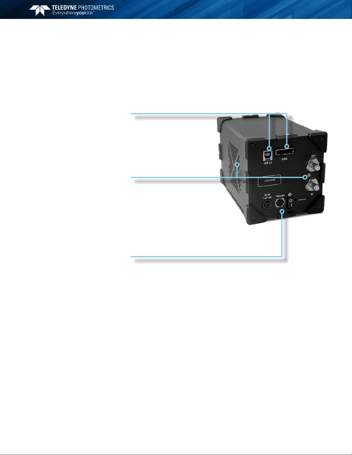
Highlights of the Prime 95B camera are shown below: The Prime 95B package
includes the PVCAM drivers designed to allow you to use this camera with a
variety of third party imaging software - To see a list of supported software, visit
the Teledyne Photometrics website.
Figure 1
• USB3.0: Lower Speed Data Connection.
• DATA : High Speed PCI-Express Connection.
• Out/In: Liquid Cooling Connections.
• Initializing: LED blinking indicates the camera is booting up.
• Power Switch: Turns the camera on and o.
• Trigger: Hirose HR10A-10R-10S for use with Teledyne Photometrics’
trigger to BNC break out cable CBL-IO-8-BNC.
• DC IN: Connection to external 12V 10A DC power supply.
Unless there is a preferred version specified by a third party software provider, the
latest version of PVCAM is recommended for use with Prime 95B.
Getting to Know Prime 95B
Software Compatibility
Requirements
16-bit Data
°° 41 fps
12-bit Data
°° 80 fps
Forced Air Cooling
°° -20°C Cooling
°° Selectable Fan Speed
Liquid Cooling
°° -25°C Cooling
°° Leak-proof, quick-disconnect ports
Eective Global Shutter
Up to four selectable expose-out lines
Convenient Interfaces
Multiple Cooling Options
Advanced Application Triggers

5
Prime 95BTM Scientific CMOS User Manual
The host computer (PC) for Prime must meet the following minimum requirements:
• Windows 7/8/10 64-bit operating system
• 2.0 GHz or faster Intel processor: either Xeon or Core i7
• 8+ GB RAM
• 250+ GB serial ATA (SATA) HDD and/or >512 GB solid state drive (SSD)
for high-speed imaging and storage
• 512+ MB slot-based ATI/NVIDIA video graphics card (i.e., not an
“onboard/integrated graphics” adapter)
• USB port for use with the USB memory device or Internet access to
obtain the PVCAM library and interface drivers
• USB3.0 port for use with the Prime USB3.0 interface
• An open PCI-Express 4x (4 lane) interface slot or higher for use with the
Prime PCIe interface card
An appropriate Installation Guide is included as an insert with the camera. This
guide provides step-by-step instructions for installing the camera interface
software for Windows-based computers. Additional instructions are included for
installing a PCI Express interface card in the computer.
The Teledyne Photometrics USB memory device contains the following files:
• Manuals Directory — contains user manuals in PDF format.
• Customer Case Studies — application examples
• Imaging Software – a copy of Open Imaging’s FOSS Application,
Micromanager
• Technical Notes – detailed background on advanced features
• For a 64-bit Windows OS, install the PVCam driver.
• Follow the Installation Guide insert for the version of Windows being
used. Reboot the computer when the installation is complete.
As CMOS cameras have developed, the amount of data generated from these
products has exceeded the current capabilities of USB interfaces. The Prime
CMOS camera platform provides both USB 3.0 for convenience and a PCI-
Express interface to ensure that the camera is capable of sustaining the required
bandwidth of the camera.
The data rate of the Prime 95B camera is sustainable through both the USB 3.0
and PCI-Express interfaces.
Host Computer Requirements
Software Installation
Installing the PCI Express
Interface Card
6
Prime 95BTM Scientific CMOS User Manual
TIP: PCI Express is a high speed peripheral data bus used by the computer to
communicate with video cards, high speed Solid State Drives, and image frame
grabbers. The PCI Express interface card is simply an adapter between the
computer’s internal PCIe bus and the camera.
While this has benefits in cost, reliability, simplicity, and performance, it is
important that the camera is powered on for 30 seconds before starting the
PC. This will ensure that as the computer goes through the boot process, it
discovers the camera on the PCIe bus.
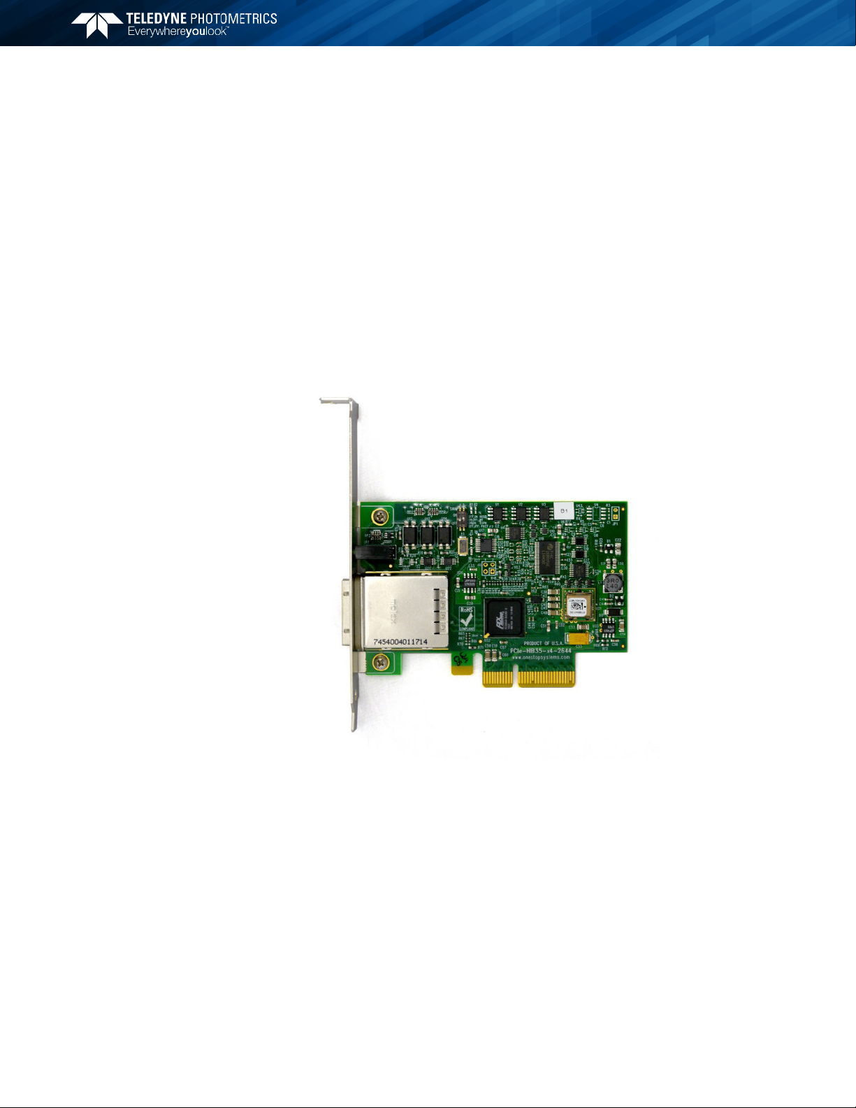
Install the High Speed PCI Express Interface
Figure 2
Note: The model of PCIe card shipped with the camera may dier from the one
shown in the photo.
Warning: Do not use the PCIe interface supplied with the QImaging optiMOS
sCMOS camera with the Teledyne Photometrics Prime 95B camera. While they
have a common cable and connector, they are not compatible.
7
Prime 95BTM Scientific CMOS User Manual
Before attempting to operate the camera, first install this interface card into the
PC with the following steps:
1. Shut down the PC
2. Unplug the PC from power mains and ensure the camera is turned o
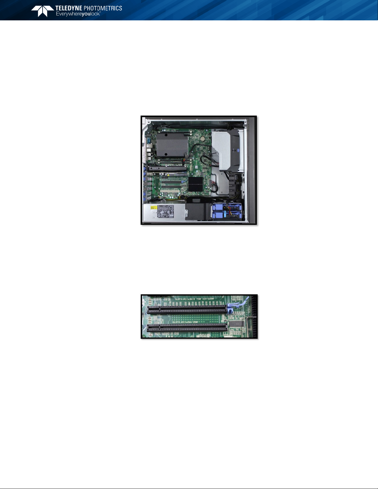
3. Open the side of the computer to access the PCI and PCIe slots
Figure 3
4. Locate an available 4 channel or higher PCIe slot (marked x4). Refer to
the PC’s documentation to locate a suitable slot.
Tip: The PC may have motherboard slot information on the side cover
Figure 4
5. Holding the Prime PCIe card and (being careful not to touch the board
components or PCIe bridge pins) insert it with the proper orientation into the
open slot. The card should slide into place with minimal resistance and snap
when fully inserted.

8
Prime 95BTM Scientific CMOS User Manual
The Prime 95B camera data cable is a quick insertion, quick release cable that
works with the interface card and camera. Either end of the cable can be plugged
into either device, and in any order.
Figure 5
The connector can only be inserted with the correct orientation, do not force
the connector. If the connector does not insert, simply turn the connector over
and retry.
With the cable connected on both ends of the camera, it is ready to power on
the computer.
1. Verify that the power switch on the side of the camera is in the o
position.
2. Connect the power supply to the Power connector on the rear of the
camera.
3. Plug the power cord into the power supply and then into a suitable
wall outlet.
4. Switch on the camera (power switch on the side of camera).
5. Wait 30 seconds before powering on the PC
Tip: The power supply and connector used by the Prime 95B camera is a
common type. However, Teledyne Photometrics carefully selects power
supplies for optimum noise performance, EMI compliance and stability. Do not
swap power supplies with other lab equipment even though they may meet the
connector, voltage and ampere requirements of the Prime.
Connecting Prime
to the PCIe Bus
9
Prime 95BTM Scientific CMOS User Manual
Prime’s USB3.0 interface is ubiquitous and easy to use. To use the interface, the
PC must have an open USB3.0 port. Prime is not USB2.0 compatible. USB3.0
ports are usually indicated by the SuperSpeed+ logo and are typically blue in
color.
Tip: USB devices sharing the same bus as the Prime 95B contend for available
bandwidth, potentially causing the camera to drop frame rate. For this reason,
Teledyne Photometrics recommends isolating the camera to its own USB3.0
root hub as shown in the Windows Device Manager.
A method for creating an independent root hub in computers with many USB
devices is to install a PCI Express based USB3.0 interface card for use with
the camera. In this case Teledyne Photometrics recommends using the PCIe
interface described above.
It is not recommended to connect to the Prime 95B external USB3.0 hubs.
Figure 6
Note that the ends of the USB3.0 cable are dierent between the camera and
PC, and require a specific orientation. The camera has a “Type B” connector
and the computer will have a “Type A” connector. Do not force insertion when
connecting the cable – if significant resistance is encountered stop, reexamine
the connection, and if correct, retry.
With the cable connected on both ends, you are now ready to power on the
computer:
1. With the camera o, connect the USB3.0 cable between camera
andhost computer.
2. Power the camera on.
3. Wait 30 seconds before launching the application. An LED on the rear
of the camera will stop blinking when the camera is initialized and
ready to communicate.
Connecting Prime
with USB 3.0

10
Prime 95BTM Scientific CMOS User Manual
Backside illuminated scientific CMOS (BSI Scientific CMOS) sensors are a recent
development in image sensor technology. BSI CMOS sensors are able to provide
the highest levels of sensitivity with a near perfect 95% quantum eciency (QE).
This QE coupled with large pixel CMOS sensors which have high frame rates,
high pixel counts, and low electronic noise provide the most complete low-light
scientific imaging solution.
A major dierence between traditional CCD sensors and CMOS sensors is the
location where charge-to-voltage conversion of accumulated photoelectrons
takes place. CCD sensors transfer the pixels accumulated signal in charge packets
in “bucket brigade” fashion across the sensor to a common output node where
charge is converted to a voltage. The voltage is then sampled using o-chip
Analog-to-Digital Converters (ADC) and transferred to the PC as digital grey
values.
While providing excellent quantitative photometry and very high image quality,
the large number of transfers and sequential digitization of pixels results in low
frame rates. This speed penalty increases with the number of pixels to be digitized.
CMOS sensors leverage many of the same analog signal concepts used in CCDs,
but places the output node circuitry inside each pixel. This eliminates the charge
transfer process. To read the signal from a given row, the accumulated charge is
converted to a voltage inside the pixel, then each pixel in the row is connected to
the appropriate column voltage bus, where the on-chip ADCs covert the voltages
to an 11-bit or 12-bit grey value. (Thus far, the on-chip ADCs available on CMOS
sensors have limited dynamic range.)
The parallel digitization of all pixels in a row provides CMOS devices with a
tremendous speed advantage. Imagine a CCD with 1200x1200 pixels – and
each pixel’s voltage is measured in 1 µsec. To read a single row, 1200 voltage
measurements are performed in serial fashion taking slightly longer than 1 ms,
and when repeated for 1200 rows, the entire image takes over 1 second to be
digitized.
On a CMOS device – the entire 1200 voltage conversions needed to digitize a row
happen in parallel.
Introduction
CMOS Image
Sensor Structure
Chapter 3 – Theory of Operation

11
Prime 95BTM Scientific CMOS User Manual
If the time to digitize a pixel remains at 1 µs – the time to read the entire frame
is now 1.2 ms. In practice, the time saving is split between faster frame rates and
slowing the rate of pixel measurement to reduce electronic noise. For example,
if the time to measure a pixel was increased to 10 µsec to lower noise, the image
sensor can still be read in 12.5 ms (for a maximum 80fps).
Of course, there are many challenges to obtaining the same analog performance
from each of the Prime 95B’s 1.4 million pixels, whereas a CCD has a single,
common output node resulting in a uniform response. The most common
problems are pixel-to-pixel non uniformity in gain and oset, random
telegraph noise (RTN), and defective pixels with abnormal noise or dark current
characteristics (hot pixels).
Often solutions to these challenges are found in the digital domain, where Prime
95B’s advanced real time signal processing corrects each pixel for gain and oset
variation using calibration at the factory. To address RTN and other pixel defects,
real-time digital filters are used. These corrections are described further in this
manual.
As discussed in the previous sections, the column ADCs present in scientific
CMOS devices have limited dynamic range. This is addressed by making two
measurements of the accumulated charge in each pixel – the first with very high
sensitivity but limited to a maximum signal of approximately 1000 electrons, and
the second with reduced sensitivity but capable of measuring signals up to the
pixel’s 80,000 electron full well capacity.
Combining the two measurements into a single 16-bit value is the function of
the digital “gain combiner.” This mathematical operation is performed on the
cameras FPGA. The result is a single gain of approximately 1.2 e-/ADU.
In practice, the Prime 95B oers both a combined ADC 16-bit output as well as a
12-bit single ADC output. The combined gain takes two measurements of a pixel
for the combined ADC 16-bit output. The 12-bit mode is able to sample 2 rows
simultaneously as only a single sample is required resulting in a 2X increase in
frame rate.
Since the 12-bit mode does not have the flexibility in dynamic range provided
by gain-combining, multiple gain states are provided so that acquisition can be
optimized for the required performance. These gain states are:
• Full Well - Provides maximum full-well capacity with a gain conversion
factor of ~2e-/ADU
• Balanced - Provides the best balance between read noise and full-well
capacity with a gain conversion factor of ~1e-/ADU
• Sensitivity - Provides the highest levels of sensitivity with a gain
conversion factor of ~0.5e-/ADU
Gain Combining
and Bit-Depth

12
Prime 95BTM Scientific CMOS User Manual
Rolling Shutter and Global Shutter are the two primary operating modes of CMOS
image sensors. In Global Shutter readout, a global charge clearing mechanism
begins the exposure period for all pixels. Each pixel accumulates signal charge
until the exposure period ends. At this point, the accumulated charge is transferred
and converted to a voltage in the pixels output node, ending the exposure.
The strength of the Global Shutter approach is that all pixels are exposed at the
same instant in time – an important attribute when imaging fast moving objects.
The downside of this approach is the sensor has two phases, an active image
accumulation phase and a subsequent readout phase. As the phases are not
overlapped in time, the maximum achievable frame rate is lower.
In Rolling shutter readout, exposure and readout are overlapped. This is
accomplished by reading one row, while exposing all of the other rows (The row
being digitized “rolls” through the sensor).
For Prime 95B, the time to digitize a single row is 20µs, and consequently the
delay between the start of exposure between two adjacent rows is approximately
9.6µs. Digitizing 1200 rows of pixels, the time delay from the top to the middle of
the sensor is approximately 24 ms. Since readout and exposure are overlapped,
the sensor achieves the maximum frame rate of 41fps. In the 12-bit mode, as
two rows are read out simultaneously, the row time is eectively halved to 10µs,
providing an increase maximum frame rate of 80fps.
The graphic below depicts the time delay between each row of pixels in a rolling
shutter readout mode with a CMOS camera.
Figure 7: Rolling Shutter Exposure Row by Row Exposure Start/End Oset
The downside of Rolling Shutter readout is that changes in the scene on similar
time scales is distorted, as each row samples the image at dierent times. This is
the well known “rubber band” eect – but can appear in fluorescence microscopy
as shaded illumination when rapidly changing wavelengths.
To maintain the benefit of Rolling Shutter readout and eliminate rolling shutter
artifacts, external illumination can be gated on when all rows are being
simultaneously exposed, and o during the readout phase. This external triggering
mode used in combination with high speed light sources (lasers, LEDs) achieves
a pseudo global shutter eect. This triggering mode is described in the device
synchronization section of this manual.
Rolling and Global
Shutter Readout
Table of contents
Other Teledyne Photometrics Digital Camera manuals


Popular Digital Camera manuals by other brands


Pentax
Pentax ZOOM 105-R operating manual

Olympus
Olympus E620 - Evolt 12.3MP Live MOS Digital SLR... instruction manual

Samsung
Samsung Vluu PL20 Manual Del Usuario
Samsung
Samsung BL103 - 10.2 Mega Pixels Digital Camera Manual de usuario

V-TAC
V-TAC VT-5157 Installation instruction

Sony
Sony Cyber-Shot DSC-RX10M4 Help guide